1
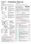
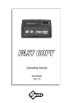
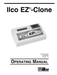
Installation Manual
Prox manual
V1
for
603ABP Wireless Intercom System
Testing
Installation
1) Before installing fully, test the range of the system. Wire the unit as per
wiring diagram, place the equipment in the desired location and test
operation.
2) Ensure that the gate transmitter / receiver unit is installed to facilitate
line of sight with the property or reception area. To achieve best results,
mount the unit as high as possible from the ground. Should you need to
extend range, you can mount it on a small pole to elevate it a few meters
from the ground.
House or
reception
area
150m
Typical
Entrance
Pillar
For longer range
applications, locate the
handset near a window at
front of property.
Note: Wood and glass only
reduce signal strength by
10-20%. Masonry will reduce
signal strength by 20-50%
per wall. Metal can totally
block signals.
Transmitter / receiver - Keep
away from ground, as high as
possible. For best results, do
not install too close to sources
of electrical interference e.g.
gate automation panel
Speech
Unit
3) It is recommended to charge the handset for 7-8 hours before use.
4) Power up the handset after inserting the batteries.
5) Wire the door station and transmitter / receiver according to the diagram
below..
3) Remove the top two security
screws as shown. Do NOT remove
the bottom screws.
Call Button
The front door will hinge downwards
to allow access for mounting holes
and connection terminals.
Optional prox
module
ARCHITECTURAL
MODEL
HOODED
MODEL
Note: The protective film on the front
of the intercom should not be removed
until fully installed.
Mount AB model
to wall with
Never drill holes in
10mm x 50mm
the top of the
large wall
enclosure. Cable
anchors to
entry should be
prevent removal
through the bottom.
or theft.
4 meters max
Screened CAT 5
Intercom
Note: For
improved audio,
connect shield
to metal on
speech panel.
MIC
connections
Foil screening
wrapped
around MIC
wires for best
performance!
+
GND
Solid
shield
wire
5sec
1sec
set
run
N/C C N/O
Output
Status LED
CHANGE RING TONE
Press
and the unit will ring under
the currently select tone. Press
and
to cycle through available
ring tones. Press MENU to select
and save.
CHANGE LANGUAGE
Press
and the unit will display the
currently selected language.
1=English. Press
and
to
cycle. Press MENU to select and
save.
Reception
indicator
Battery
Level
12.21
Voicemail
Symbol
Vibration
ON/OFF
ON/OFF
MENU
Charging
base
Code
Button
Power
LED
VOICEMAIL
When the door station is pressed, and not answered within 40 seconds,
the visitor can leave a message. Once complete, the handset will display
the
symbol. Up to 16 messages can be saved.
To listen to voicemail, press MENU to play. If there are more than 1
message, press
and
to select the message required and press
MENU to play.
= Pause / Exit
= Continue
= Delete, long
press = delete all.
SET TIME ON DISPLAY
Press MENU for 2 seconds. The hour digits will begin flashing.
Press
or
to adjust. Press MENU to cycle from hour setting to
minutes and repeat. Press MENU a third time to exit and save changes.
Coding another handset to the System
To add an extra handset to the system, follow the sequence below..
1) Press and HOLD the code button on the door station for 3 seconds,
until the LED’s on the bottom of the board start to flash.
2) Press and hold the Code button on the new handset ignoring the first
short tone, until you hear a confirmation tone (“Di-Do-Do”). This may take
up to 10 seconds.
3) Once the door station lights stop flashing, then you can test the
system by pressing the call button on the door station. The new handset
should ring. If not, repeat the process from the top.
Note: For earlier models, the existing master handset lights will
flash after step 1. You will need to press the MENU button on the
existing handset first, before proceeding to step 2 above.
Proximity reader
12v dc
ADJUST VOLUME
Press or
to adjust volume level,
and press MENU to select and save.
602 Range
Code
button
- +
Handset & Operation
Transmitter
(keep short for better audio)
12v
dc
+ - + -
1) Check all connections are correct before switching on the power.
2) Press the call button on the speech panel.
3) The handset should ring.
4) Press the
button to answer the call and check two way speech.
5) Press
to check the door / gate release function works.
-+
12v
dc in
Volt free
Relay output
(4 sec pulse)
Shielded CAT5 cable
Green when in Add tag mode & relay active
RED when in SET mode, & delete tag mode.
Double flash when error.
Note: Prox unit volt free output needs connected to gate control panel or electric door
lock as well as relay output from the intercom controller PCB. Parallel connect C and N/O
contacts for electric gate controller or strike lock. Series connect C and N/C contacts for
magnetic lock.
Proximity Module Features
Overview
The prox unit is a simple standalone device which can store up to 1000
tags.
The unit normally comes with 2 master tags and 3 user tags.
One of the master tags is an add tag, and one is a delete tag.
Add
Tag
Delete
Tag
User
Tag 1
User
Tag 2
User
Tag 3
Adding a Tag
To add a new tag…
1) Swipe the Add tag on the reader. The green LED should come on.
2) Swipe each new tag on the reader. The unit should give a single bleep
for each tag.
Swipe the Add tag again. The green LED should go off.
3) Wait 5 seconds, and swipe the new tags again to check they activate
the relay.
Deleting a Tag
To delete a tag…
1) Swipe the Delete tag on the reader. The LED should be RED.
2) Swipe the tags to be deleted on the reader. A bleep should be heard for
each Tag.
3) Swipe the Delete tag again. The RED LED should go off.
3) Wait 5 seconds, and swipe the deleted tags again to ensure they do not
operate the relay.
Setting up a new Add and Delete Tag
To create a new add and delete tag from the beginning the entire memory
will be deleted...
SET
1) Power off the prox unit.
2) Move the jumper on the prox PCB from RUN to SET.
RUN
3) Switch on the power. The RED LED should be on.
4) Swipe the tag which you wish to be the new Add tag (the unit should
bleep).
5) Swipe the tag which you wish to be the new Delete tag.
The unit should give a long bleep to indicate programming is complete.
6) Power off the prox unit.
7) Move the jumper back to the RUN position and switch on power again.
8) You may now swipe the ADD tag followed by tags you wish to add to
the unit.
Prox Relay time settings
The relay on the Prox unit is a volt free momentary relay.
Power capacity – up to 2A at 24v ac.
The relay time can be set for either 1 second or 5
seconds with the jumper link as shown,,,
5 sec
1 sec
Proximity Module Specifications
-125KHz, compatible with 4001 / 4100, EM / TEMIC / TK and other low
frequency cards.
-1 second & 5 second selectable output relay, N/C and N/O volt free.
-Scan range of 50mm.