1
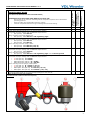
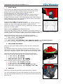
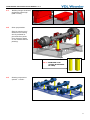
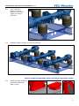
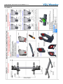
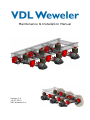
Maintenance & Installation Manual Version 1.2 14-07-2010 VDL Weweler b.v. MAINTENANCE AND INSTALLATION MANUAL V1.2 CONTENTS Page 1. Introduction 1 2. Maintenance work - Overview - Air springs - Shock absorbers - U-Bolts - Pivot Bolts - Air spring supports - Axle lifts 2 3. General information 5 4. Air suspension systems installation instructions & guidelines - General instructions - System Assembly before mounting to the chassis - Chassis welding preparation before mounting Suspension System 6 9 12 APPENDIX A : IM-052 16 APPENDIX B : IM-053-DOC 17 APPENDIX C : WM-A-DOC 18 APPENDIX D : WM-C-DOC 19 THIS DOCUMENT IS SUBJECT TO CHANGE (WITHOUT NOTICE). NO RIGHTS CAN BE CLAIMED FROM THIS DOCUMENT. WEWELER IS NOT RESPONSIBLE FOR ANY ERRORS, MISPRINTS OR OMISSIONS IN THIS PUBLICATION. 0 MAINTENANCE AND INSTALLATION MANUAL V1.2 INTRODUCTION The maintenance intructions in this manual covers Weweler air suspension systems. It is essential to observe the maintenance intervals specified by the manufacturer, this will ensure continuous operational safety and roadworthiness. If the operator of the trailer does not have the required technical equipment and/or expertise is not officially authorised to carry out intermediate inspections, contact Weweler. (see http://www.vdlweweler.com) They can supply detailed technical information and the correct procedure for replacing worn parts. Ensure that when fitting replacement components, only fit Weweler genuine parts. This will avoid invalidating warranties, type approvals, local and international regulations. Weweler air suspension systems are low maintenance systems. For this reason, all moving parts are rubber/steel Bushing; this avoids the need for lubrication during regular service intervals. The specified torque settings and high clamping forces ensure that the steel inner bushes cannot turn. The rubber part of the component accommodates the turning movement, when required. 1 Operations to be done each time before you drive off: - - Ensure that the air reservoir of braking and air suspension systems have reached their operating pressure. Drain the water and condensation from the system. Check air suspension bellows for sign of damage and incorrect seating. - Visual inspection. Check all component parts for damage and wear. 1 Check condition of air springs. 2 Check shock absorber fastening for the correct torque loading. Field check of torque settings with a calibrated torque wrench: 9 M20 (SW 30) M = 550 Nm When mounting new shock absorber kit: 9 M20 (SW 30) M = 200 Nm + 180° tightening angle 3 Check the axle-clamp U-bolts for the correct torque loadings. Field check of torque settings with a calibrated torque wrench: 9 M22 (SW 32) M = 600 Nm 9 M24 (SW 36) M = 800 Nm When mounting new axle clamp U-bolts: 9 M22 (SW 32) M = 600 Nm (+25/-0) 9 M24 (SW 36) M = 800 Nm (+50/-0) 4 Check the pivot bolts for the correct torque loadings. Field check of torque settings with a calibrated torque wrench: 9 M27 (SW 41) M = 1000 Nm When mounting new trailing arms: 9 M27 (SW 41) M = 250 Nm + 270° tightening angle + ¼ of thread greased 5 Check air spring & offset plate fastening for the correct torque loadings. Field check of torque settings with a calibrated torque wrench: 9 A: M12 (SW 19) M = 30 Nm 9 B: M12 (SW 19) M = 50 Nm 9 Offset plate M12 (SW 19) M = 50 Nm 9 Offset plate M16 (SW 24) M = 200 Nm When mounting new air springs / offset plates: 9 A: M12 (SW 19) M = 30 Nm (+10/-0) 9 B: M12 (SW 19) M = 66 Nm (+0/-16) 9 Offset plate: M12 (SW 19) M = 66 Nm (+0/-16) 9 Offset plate: M16 (SW 24) M = 200 Nm (+20/- 20) 6 Check axle lift for the correct torque loadings. See axle lift data sheets for the correct torque settings for each axle lift. ANNUALLY ** (FOR DETAILLED DESCRIPTION SEE FOLLOWING PAGES) INITIALLY AFTER 2 WEEKS * MAINTENANCE WORK EVERY 26 WEEKS (TWICE ANNUALLY) MAINTENANCE AND INSTALLATION MANUAL V1.2 ● ● ● ● ● ● ● ● ● ● ● ● * After the first run under load conditions. ** Under extreme conditions with more frequency. 2 MAINTENANCE AND INSTALLATION MANUAL V1.2 1. AIR SPRINGS Check air springs, every 6 months, for external damage like surface cracking, abrasion, trapped debris etc. Notice: No welding should be carried out on the steel parts of the air springs and pressure vessel! The air suspension should only be filled with compressed air when mounted on the vehicle. 2. SHOCK ABSORBERS Check shock absorber fastening annually and initially after 2 weeks. Check lower and upper shock absorber fastening for tightness. Field check of torque settings with a calibrated torque wrench: 9 M20 (SW 30) M = 550 Nm When mounting new shock absorber kit: 9 M20 (SW 30) M = 200 Nm + 180° tightening angle During vehicle maintenance, “sweating“ shock absorbers are often criticised and replaced because the phenomenon “sweating “shock absorber is often confounded with leakage. This “sweating“ is actually a normal and necessary process, by which the piston rod pulls up a light oil film with each stroke. This oil film is necessary to protect the shaft seal against fast abrasion which could lead to the leaking of the shock absorber. On bad roads shock absorbers can reach an operating temperature of over 180°C, causing the oil film, pulled up by the piston rod, to evaporate on the piston rod and depending on environmental condition condensate on the dust cover. This evaporation sets itself as an oil film on the outside of the shock absorber. PLEASE NOTE THE FOLLOWING: • Check the shock absorber in dry conditions. Not in rainy weather conditions. • Light “sweating” is allowed. • With a failure “leakage” the shock absorber will loose all of the oil. • If in doubt, clean the shock absorber and check again after two days. In case of failed shock absorber bushes, the shock absorber should be replaced. Trying to move the shock absorber with it is fastened, enables you to simply detect excessive wear of rubber bushes. Observing the specified torque setting ensures that the steel inner bush will not get twisted and that the torsional motion is accommodated by the rubber part alone. 3. U-BOLTS Check U-bolts fastening annually and initially after 2 weeks. Check nuts of the U-bolts for tightness. If loose, tighten nuts alternately a little at a time. Field check of torque settings with a calibrated torque wrench: 9 M22 (SW 32) M = 600 Nm 9 M24 (SW 36) M = 800 Nm When mounting new axle clamp U-bolts: 9 M22 (SW 32) M = 600 Nm (+25/-0) 9 M24 (SW 36) M = 800 Nm (+50/-0) Align the system acc. IM-053-DOC. Notice: No welding should be performed on the trailing arm! 3 MAINTENANCE AND INSTALLATION MANUAL V1.2 4. PIVOT BOLTS Check pivot bolts fastening annually and initially after 2 weeks. Using the specified torque settings ensures that the steel inner bush(5) will not get twisted and the torsional motion is accommodated by the rubber part(4) alone. Check bushes, move the vehicle back and forth slightly with the brake applied, or lever rolled spring ends with the aid of a bar. No play should be present in the rolled spring eye(6) when doing so. If the fastening is loose the pivot bolt(2) may be worn or damaged. Replace damaged parts immediately! Hanger bracket with axle alignment device: Check the wear plates(3) that are located on the hanger bracket(1). If these are worn to the point that perfect clamping of the steel inner bush(5) is no longer insured, replace the complete rubber bush and the wear plates. Hanger bracket without axle alignment device: Check the wear plates(3) that are welded to the hanger bracket(1). If these are deteriorated to the point that perfect clamping of the steel inner bush(5) is no longer insured, replace the complete rubber bush and the hanger bracket. Check the M27 lock nut(8) on the pivot bolt for tightness. Field check of torque settings with a calibrated torque wrench: 9 M27 (SW 41) M = 1000 Nm When mounting new trailing arms: 9 M27 (SW 41) M = 250 Nm + 270° tightening angle + ¼ of thread greased Also when mounting a trailing arm align the system acc. IM-053-DOC. 5. AIR SPRING & SUPPORT Check air spring (& support) fastening annually and initially after 2 weeks. The different types of air springs can be mounted directly on the trailing arm or with a seperate bellow support. This depends on the type of air suspension system used and the desired air spring offset. Check air spring & support fixing bolts or nuts for tightness. Field check of torque settings with a calibrated torque wrench: 9 A: M12 (SW 19) M = 30 Nm 9 B: M12 (SW 19) M = 50 Nm 9 Offset plate M12 (SW 19) M = 50 Nm 9 Offset plate M16 (SW 24) M = 200 Nm When mounting new air springs / offset plates: 9 A: M12 (SW 19) M = 30 Nm (+10/-0) 9 B: M12 (SW 19) M = 66 Nm (+0/-16) 9 Offset plate: M12 (SW 19) M = 66 Nm (+0/-16) 9 Offset plate: M16 (SW 24) M = 200 Nm (+20/- 20) 6. AXLE LIFT Check axle lift fastening annually and initially after 2 weeks. The torque settings for the axle lifts depends on the type of axle lift. See the axle lift data sheets for the corresponding torque settings for each axle lift. 4 MAINTENANCE AND INSTALLATION MANUAL V1.2 GENERAL INFORMATION • Suspension Stop The air suspension systems have been engineered so that the shock absorber acts as the suspension stop. The shock absorbers can withstand heavy-duty service, which obviates the need for arrester cables or other suspension stops. In order to cope with the situation where the air suspension system has lowered without air, a rubber buffer in the air spring exists. If an air spring failure develops, the rubber buffer inside enables you to run (without air) at very low speed for a short period of time. This will help you to get to the nearest service station. To prevend further damage, always make sure that there is enough clearance for all moving parts. • Lifting and lowering valve Use the raise-lower valve ONLY for loading and unloading. When driving the vehicle, be sure that you have selected “driving position” on the valve. Driving with the air suspension valve set to “RAISE” may cause damage to the load, the semi-trailer, the brakes and the suspension system, and leads to shock absorber overloading and eventually the failure of the system. 5 MAINTENANCE AND INSTALLATION MANUAL V1.2 AIR SUSPENSION SYSTEM INSTALLATION INSTRUCTIONS & GUIDELINES 1. Set spring track. 2. Place axle seats. 3. Place axle. 6 MAINTENANCE AND INSTALLATION MANUAL V1.2 4. Align axle. 5. Check position air cylinder bracket for drum brakes or booster angle in case of disc brakes. Mind under- or overslung systems. 6. Tack weld axle seats. TO PREVENT DAMAGE TO THE BEARINGS, NEVER CONNECT THE EARTH CONNECTOR TO THE AXLE HUB OR WHEEL END! 7. Place axle on supports. 7 MAINTENANCE AND INSTALLATION MANUAL V1.2 8. Welding preperation 9. Inverted welding. (WM-A-DOC) DO NOT WELD AXLE SEAT TO TRAILING ARM! INVERTED WELDING ROTATE AXLE ACCORDING STEP 8 AND WELD AXLE SEATS COMPLETE TO THE AXLE. TO PREVENT DAMAGE TO THE BEARINGS, NEVER CONNECT THE EARTH CONNECTOR TO THE AXLE HUB OR WHEEL END! 10. Place trailing arms, U-bolt plate, U-bolts and nuts (& washers). DO NOT TIGHTEN AT TORQUE BEFORE ALIGNING! Always place center bolt head in the axle seat! 8 MAINTENANCE AND INSTALLATION MANUAL V1.2 11. Align trailing arms with axle. 12. Tighten U-bolt at torque. See image for tightening sequence. (IM-052) DO NOT WELD U-BOLT PLATE TO TRAILING ARM! After step 12 there are two options to complete the system assembly: a. First assemble the hanger brackets to the system and then weld the complete system to the trailer chassis (follow steps 13-21). b. First weld the hanger brackets and pedestals (if applied) to the trailer chassis and then mount the air suspension with axle to the hangerbrackets and pedestals (follow steps 22-29). System Assembly before mounting on chassis 13. Place hanger brackets and pivot bolts and use mounting tool (as shown in drawing) to tighten the pivot bolt at ride height. Tighten pivot bolt at torque. (IM-052) 13.1 - MOUNTING TOOL 9 MAINTENANCE AND INSTALLATION MANUAL V1.2 14. Remove mounting tool and place shock absorbers so that the code can be read. And, if present, follow the instructions on the shock absorber. Tighten top & bottom at torque. (IM-052) 15. Place system upside down on to the chassis (all three axles). 16. Align all three axles within tolerances. A = Kingpin. B to G are axle centers. 10 MAINTENANCE AND INSTALLATION MANUAL V1.2 17. Welding hanger brackets, pedestals & bracings. (WM-C-DOC) 18. Paint preparation. Place a painting tool between the trailing arm & pedestal to prevend the system from dropping down on the chassis before painting. 18.1 - PAINTING TOOL (SHAPE & MATERIAL IS FREE) 19. Painting suspension system + trailer. 11 MAINTENANCE AND INSTALLATION MANUAL V1.2 20. Final assembly. Mount air spring bellows on all axles. Tighten at torque. (IM-052) 21. Finished product (Ready for wheel mounting). Chassis welding preperation before mounting suspension system 22. Welding hanger brackets, pedestals & bracings. (WM-C-DOC) 12 MAINTENANCE AND INSTALLATION MANUAL V1.2 23. Paint preparation. Cover all areas which must be clear from paint. See instruction IM-053-DOC. 24. Place suspension system on the chassis with hanger brackets after painting. 25. Place pivot bolts and tighten the pivot bolts at ride height. Align the axle in the axle seat. When aligning takes place in the hangerbracket. Tighten AFTER aligning, see step 26. (IM-052 & IM-053-DOC). 13 MAINTENANCE AND INSTALLATION MANUAL V1.2 26. Align all three axles within tolerances. A = Kingpin. B to G are axle centers. Tighten pivot bolts in case of adjustable hanger brackets (see step 25). 27. Place shock absorbers so that the code can be read. And, if present, follow the instructions on the shock absorber. Use a tool between the trailing arm & pedestal to prevend the system from dropping down on the chassis Tighten top & bottom at torque. (IM-052) 28. Final assembly. Mount air spring bellows on all axles. Tighten at torque. (IM-052) 14 MAINTENANCE AND INSTALLATION MANUAL V1.2 29. Finished product (Ready for wheel mounting). 15 MAINTENANCE AND INSTALLATION MANUAL V1.2 APPENDIX A 16 MAINTENANCE AND INSTALLATION MANUAL V1.2 APPENDIX B 17 MAINTENANCE AND INSTALLATION MANUAL V1.2 APPENDIX C 18 MAINTENANCE AND INSTALLATION MANUAL V1.2 APPENDIX D 19