1
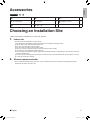
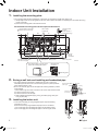
English
INSTALLATION MANUAL
Deutsch
DAIKIN ROOM AIR CONDITIONER
FTXS35K2V1B
FTXS42K2V1B
FTXS50K2V1B
00_CV_3P320971-1B.indd 1
Nederlands
Español
Türkçe
MODELS
Pyccкий
Portugues
Eλληνικά
Italiano
Installation manual
Installationsanleitung
Manuel dinstallation
Installatiehandleiding
Manual de instalación
Manuale dinstallazione
Εγχειρίδιο εγκατάστασης
Manual de instalação
Руководство по монтажу
Montaj kılavuzları
Français
R410A Split Series
1/8/2013 2:31:07 PM
EN60335-2-40,
FTXS35K2V1B, FTXS42K2V1B, FTXS50K2V1B
DAIKIN INDUSTRIES, LTD.
,
,
Shinri Sada
Manager Quality Control Department
Low Voltage 2006/95/EC
Machinery 2006/42/EC **
Electromagnetic Compatibility 2004/108/EC *
Umeda Center Bldg., 2-4-12, Nakazaki-Nishi,
Kita-ku, Osaka, 530-8323 Japan
74736-KRQ/EMC97-4957
DEKRA Certification B.V. (NB0344)
DAIKIN.TCF.015 P9/09-2012
3SB65451-17F.fm Page 1 Tuesday, October 16, 2012 5:25 PM
3SB65451-17F
3SB65451-4.fm Page 2 Thursday, October 27, 2011 4:49 PM
Safety Precautions
•TheprecautionsdescribedhereinareclassifiedasWARNINGandCAUTION.Theybothcontainimportantinformationregardingsafety.Besuretoobserveallprecautionswithoutfail.
•MeaningofWARNINGandCAUTIONnotices
WARNING ........Failure to follow these instructions properly may result in personal injury or loss of life.
CAUTION .........Failure to observe these instructions properly may result in property damage or personal injury, which
may be serious depending on the circumstances.
•Thesafetymarksshowninthismanualhavethefollowingmeanings:
Besuretofollowtheinstructions.
Besuretoestablishanearthconnection.
Neverattempt.
•Aftercompletinginstallation,conductatrialoperationtocheckforfaultsandexplaintothecustomerhowtooperate
theairconditionerandtakecareofitwiththeaidoftheoperationmanual.
WARNING
•Askyourdealerorqualifiedpersonneltocarryoutinstallationwork.
Donotattempttoinstalltheairconditioneryourself.Improperinstallationmayresultinwaterleakage,electricshocksorfire.
•Installtheairconditionerinaccordancewiththeinstructionsinthisinstallationmanual.
Improperinstallationmayresultinwaterleakage,electricshocksorfire.
•Besuretouseonlythespecifiedaccessoriesandpartsforinstallationwork.
Failuretousethespecifiedpartsmayresultintheunitfalling,waterleakage,electricshocksorfire.
•Installtheairconditioneronafoundationstrongenoughtowithstandtheweightoftheunit.
Afoundationofinsufficientstrengthmayresultintheequipmentfallingandcausinginjury.
•Electricalworkmustbeperformedinaccordancewithrelevantlocalandnationalregulationsandwithinstructions
inthisinstallationmanual.Besuretouseadedicatedpowersupplycircuitonly.
Insufficiencyofpowercircuitcapacityandimproperworkmanshipmayresultinelectricshocksorfire.
•Useacableofsuitablelength.
Donotusetappedwiresoranextensionlead,asthismaycauseoverheating,electricshocksorfire.
•Makesurethatallwiringissecured,thespecifiedwiresareused,andthatthereisnostrainontheterminal
connectionsorwires.
Improperconnectionsorsecuringofwiresmayresultinabnormalheatbuild-uporfire.
•Whenwiringthepowersupplyandconnectingthewiringbetweentheindoorandoutdoorunits,positionthewires
sothatthecontrolboxlidcanbesecurelyfastened.
Improperpositioningofthecontrolboxlidmayresultinelectricshocks,fireoroverheatingterminals.
•Ifrefrigerantgasleaksduringinstallation,ventilatetheareaimmediately.
Toxicgasmaybeproducediftherefrigerantcomesintocontactwithfire.
•Aftercompletinginstallation,checkforrefrigerantgasleakage.
Toxicgasmaybeproducediftherefrigerantgasleaksintotheroomandcomesintocontactwithasourceoffire,suchasafanheater,
stoveorcooker.
•Wheninstallingorrelocatingtheairconditioner,besuretobleedtherefrigerantcircuittoensureitisfreeofair,
anduseonlythespecifiedrefrigerant(R410A).
Thepresenceofairorotherforeignmatterintherefrigerantcircuitcausesabnormalpressurerise,whichmayresultinequipmentdamageand
eveninjury.
•Duringinstallation,attachtherefrigerantpipingsecurelybeforerunningthecompressor.
Iftherefrigerantpipesarenotattachedandthestopvalveisopenwhenthecompressorisrun,airwillbesuckedin,causingabnormal
pressureintherefrigerationcycle,whichmayresultinequipmentdamageandeveninjury.
•Duringpump-down,stopthecompressorbeforeremovingtherefrigerantpiping.
Ifthecompressorisstillrunningandthestopvalveisopenduringpump-down,airwillbesuckedinwhentherefrigerantpipingisremoved,
causingabnormalpressureintherefrigerationcycle,whichmayresultinequipmentdamageandeveninjury.
•Besuretoearththeairconditioner.
Donotearththeunittoautilitypipe,lightningconductorortelephoneearthlead.Imperfectearthingmayresultinelectricshocks.
•Besuretoinstallanearthleakagebreaker.
Failuretoinstallanearthleakagebreakermayresultinelectricshocksorfire.
CAUTION
•Donotinstalltheairconditioneratanyplacewherethereisadangerofflammablegasleakage.
Intheeventofagasleakage,build-upofgasneartheairconditionermaycauseafiretobreakout.
•Whilefollowingtheinstructionsinthisinstallationmanual,installdrainpipingtoensureproperdrainageand
insulatepipingtopreventcondensation.
Improperdrainpipingmayresultinindoorwaterleakageandpropertydamage.
•Tightentheflarenutaccordingtothespecifiedmethodsuchaswithatorquewrench.
Iftheflarenutistootight,itmaycrackafterprolongeduse,causingrefrigerantleakage.
1
01_EN_3P320971-1B.indd 1
■English
12/10/2012 4:10:45 PM
Indoor unit
English
Accessories
A – H ,
A Mountingplate
1
D Remotecontrollerholder
1
G Operationmanual
1
B Titaniumapatitephotocatalytic
air-purifyingfilter
2
E DrybatteryAAA.LR03
(alkaline)
2
H Installationmanual
1
C Wirelessremotecontroller
1
F Indoorunitfixingscrew
(M4×12L)
2
Choosing an Installation Site
•Beforechoosingtheinstallationsite,obtainuserapproval.
1.
Indoor unit
•Theindoorunitshouldbesitedinaplacewhere:
1)therestrictionsoninstallationspecifiedintheindoorunitinstallationdrawingsaremet,
2)bothairinletandairoutlethaveclearpathsmet,
3)theunitisnotinthepathofdirectsunlight,
4)theunitisawayfromthesourceofheatorsteam,
5)thereisnosourceofmachineoilvapour(thismayshortenindoorunitlife),
6)cool(warm)airiscirculatedthroughouttheroom,
7)theunitisawayfromelectronicignitiontypefluorescentlamps(inverterorrapidstarttype)astheymayshortenthe
remotecontrollerrange,
8)theunitisatleast1mawayfromanytelevisionorradioset(unitmaycauseinterferencewiththepictureorsound),
9)nolaundryequipmentislocated.
2.
Wireless remote controller
•Turnonallthefluorescentlampsintheroom,ifany,andfindthesitewhereremotecontrollersignalsareproperly
receivedbytheindoorunit(within7m).
■English
01_EN_3P320971-1B.indd 2
2
12/10/2012 4:10:45 PM
Preparation before Installation
1.
Removing and installing the front panel
•Removal method
1)Placeyourfingersintheindentationsonthemainunit(oneeachonthe
leftandrightsides),andopenthefrontpaneluntilitstops.
2)Continuetoopenthefrontpanelfurtherwhileslidingthepaneltothe
rightandpullingittowardyouinordertodisengagethefrontpanelshaft
ontheleftside.Todisengagethefrontpanelshaftontherightside,slide
thepaneltotheleftwhilepullingittowardyou.
•Installation method
Front panel shaft
Alignthetabsofthefrontpanelwiththegrooves,andpushallthewayin.
Thencloseslowly.Pushthecentreofthelowersurfacepanelfirmlyto
engagethetabs.
2.
Groove
Removing and installing the front grille
Upper hook
mark area
(3 locations)
•Removal method
1)Removethefrontpaneltoremovetheairfilter.
2)Removethe3screwsfromthefrontgrille.
3)Infrontofthe
markofthefrontgrille,thereare3upperhooks.
Lightlypullthefrontgrilletowardyouwithonehand,andpushdownon
thehookswiththefingersofyourotherhand.
Push
down.
Upper hook
When there is no work space because the unit is close to ceiling
CAUTION
•Besuretowearprotectiongloves.
Placebothhandsunderthecentreofthefrontgrille,andwhilepushingup,pullittowardyou.
1) Push up.
•Installation method
1)Installthefrontgrilleandfirmlyengagetheupperhooks(3locations).
2)Install3screwsofthefrontgrille.
3)Installtheairfilterandthenmountthefrontpanel.
3.
2) Pull toward you.
How to set the different addresses
Whentwoindoorunitsareinstalledinoneroom,thetwowirelessremotecontrollers
canbesetfordifferentaddresses.
1)Removethemetalplateelectricalwiringcover.
(RefertotheRemoval/attachment methods of metal plate electrical wiring
covers.)
2)Cuttheaddressjumper(JA)ontheprintedcircuitboard.
3)Cuttheaddressjumper(J4)intheremotecontroller.
•Becarefulnottocutjumper(J8).
ADDRESS
JA
JA ADDRESS
EXIST
CUT
1
2
Jumper
(J8)
(J4)
J4 ADDRESS
EXIST
CUT
3
01_EN_3P320971-1B.indd 3
1
2
■English
12/10/2012 4:10:46 PM
English
Indoor Unit Installation Drawings
■ How to attach the indoor unit
A Mounting
plate
Hook the claws of the bottom frame
to the mounting plate.
If the claws are difficult to hook,
remove the front grille.
A Mounting plate
Claw
■ How to remove the indoor unit
Push up the lower part of the front
grille to release the claws.
If they are difficult to release,
remove the front grille.
Bottom frame
Front grille
The mounting plate
should be installed on a
wall which can support the
weight of the indoor unit.
Mounting plate
fixing screw
(field supply: M4 × 25L)
30mm or more from ceiling
Front panel
Caulk pipe
hole gap
with putty.
50mm or more
from walls
(on both sides)
Air filters
Cut thermal insulation
pipe to an appropriate
length and wrap it with
tape, making sure that no
gap is left in the insulation
pipe’s cut line.
Wrap the insulation pipe
with the finishing tape
from bottom to top.
Screws
(M4 × 16L)
Service lid
■ Opening the service lid
The service lid is opening/closing type.
■ Opening method
B Titanium apatite photocatalytic
air-purifying filter (2 pcs)
Filter frame
Air filter
1) Remove the service lid screw.
2) Pull out the service lid diagonally
down in the direction of the arrow.
3) Pull down.
C Wireless remote controller
Before screwing the
remote controller holder
to the wall, make sure
that control signals are
properly received by
indoor unit.
Tab
Titanium apatite
photocatalytic
air-purifying filter
D Remote controller
holder
Fixing screw for remote
controller holder
(field supply: M3 × 20L)
■English
01_EN_3P320971-1B.indd 4
4
12/10/2012 4:10:47 PM
Indoor Unit Installation
1.
Installing the mounting plate
•Themountingplateshouldbeinstalledonawallwhichcansupporttheweightoftheindoorunit.
1)Temporarilysecurethemountingplatetothewall,makesurethatthepaneliscompletelylevel,andmarktheboring
pointsonthewall.
2)Securethemountingplatetothewallwithscrews.
Recommended mounting plate retention spots and dimensions
Recommended mounting plate
retention spots (5 spots in all)
209
241
191.5
Use tape measure
as shown.
Position the end of
a tape measure at .
48
298
250
50
75.5
Place a leveler
on raised tab.
48
50
66
150
176
384
106
344
Throughthe-wall
hole ϕ65mm
900
Keep here the piece cut out
from the unit for piping
Liquid pipe end
* The removed pipe port cover can be
kept in the mounting plate pocket.
Gas pipe end
Drain hose position
unit: mm
Removed pipe
port cover
A Mounting plate
2.
Boring a wall hole and installing wall embedded pipe
•Forwallscontainingmetalframeormetalboard,besuretouseawall
embeddedpipeandwallcoverinthefeed-throughholetopreventpossible
heat,electricalshock,orfire.
•Besuretocaulkthegapsaroundthepipeswithcaulkingmaterialtoprevent
waterleakage.
1)Boreafeed-throughholeof65mminthewallsoithasadownslopetowardtheoutside.
2)Insertawallpipeintothehole.
3)Insertawallcoverintowallpipe.
4)Aftercompletingrefrigerantpiping,wiring,anddrainpiping,caulkpipe
holegapwithputty.
3.
Inside
Wall embedded pipe
(field supply)
Outside
Caulking
ϕ65
Wall hole cover
(field supply)
Wall embedded pipe
(field supply)
Installing the indoor unit
•Inthecaseofbendingorcuringrefrigerantpipes,keepthefollowing
precautionsinmind.
Abnormalsoundmaybegeneratedifimproperworkisconducted.
1)Donotstronglypresstherefrigerantpipesontothebottomframe.
2)Donotstronglypresstherefrigerantpipesonthefrontgrille,either.
1)
2)
5
01_EN_3P320971-1B.indd 5
■English
12/10/2012 4:10:48 PM
English
•Removethepipeportcoverasshownbelow.
1)Cutoffthepipeportcoverfrominsidethefrontgrilleusingacopping
saw.
Applythebladeofthecoppingsawtothenotch,andcutoffthepipe
portcoveralongtheuneveninnersurface.
2)Aftercuttingoffthepipeportcover,performfiling.Removetheburrs
alongthecutsectionusingahalfroundneedlefile.
CAUTION
•Ifthepipeportcoveriscutoffusingnippers,thefrontgrillewillbedamaged.Pleasedonotusenippers.
•Wearglovesduringthepipeportcoverremoval.
3-1. Right-side, right-back, or right-bottom piping
1)Attachthedrainhosetotheundersideoftherefrigerantpipeswith
adhesivevinyltape.
2)Wraptherefrigerantpipesanddrainhosetogetherwithinsulation
tape.
Right-side piping
Remove pipe port cover
here for right-side piping.
Right-back piping
Right-bottom
piping
Remove pipe port cover
here for right-bottom piping.
3)Passthedrainhoseandrefrigerantpipesthroughthewallhole,
thensettheindoorunitonthemountingplatehooksbyusingthe
markingsatthetopoftheindoorunitasaguide.
4)Openthefrontpanel,thenopentheservicelid.
(Refertopreparationbeforeinstallation.)
5)Passtheinter-unitwirefromtheoutdoorunitthroughthe
feed-throughwallholeandthenthroughthebackoftheindoor
unit.Pullthemthroughthefrontside.Bendtheendsoftie
wiresupwardforeasierworkinadvance.(Iftheinter-unitwire
endsaretobestrippedfirst,bundlewireendswithadhesive
tape.)
6)Pressthebottomframeoftheindoorunitwithbothhandsto
setitonthemountingplatehooks.Makesurethewiresdonot
catchontheedgeoftheindoorunit.
■English
01_EN_3P320971-1B.indd 6
Bind refrigerant
pipe and drain
hose together with
insulating tape.
A Mounting plate
Hang indoor unit’s hook here.
A Mounting plate
When stripping the
ends of inter-unit wire
in advance, bind right ends
of wires with insulating tape.
Inter-unit wire
Wire guide
6
12/10/2012 4:10:49 PM
Indoor Unit Installation
3-2. Left-side, left-back, or left-bottom piping
How to replace the drain plug and drain hose
•Replacing onto the left side
Drain hose attachment position
1)Removetheinsulationfixingscrewontheright
andremovethedrainhose.
2)Removethedrainplugontheleftsideand
attachittotherightside.
3)Insertthedrainhoseandtightenwithincluded
insulationfixingscrew.
*(Forgettingtotightenthismaycausewater
leakages.)
* The drain hose is on the back of the unit.
Left side
Right side
Front side of unit
Attachment on the left side
Attachment on the right side (factory default)
Insulation
fixing screw
Insulation
fixing screw
Drain hose
Drain hose
1)Attachthedrainhosetotheundersideoftherefrigerantpipes
withadhesivevinyltape.
Remove pipe
port cover
here for leftside piping.
Left-side
piping
Left-back
piping
Remove pipe port cover here for left-bottom piping.
Left-bottom piping
2)Besuretoconnectthedrainhosetothedrainportinplaceofa
drainplug.
How to set drain plug
ap.
No g
3)Shapetherefrigerantpipesalongthepipe
pathmarkingonthemountingplate.
4)Passdrainhoseandrefrigerantpipes
throughthewallhole,thensettheindoor
unitonmountingplatehooks,usingthe markingsatthetopofindoorunitasa
guide.
5)Pullintheinter-unitwire.
6)Connecttheinter-unitpipes.
Drain
hose
Caulk this hole
with putty or
caulking material.
Do not apply lubricating
oil (refrigeration oil)
when inserting.
Application of causes
deterioration and drain
leakage of the plug.
Insert a hexagonal wrench (4mm).
A Mounting plate
Bind with adhesive
vinyl tape.
7)Wraptherefrigerantpipesanddrainhosetogetherwithinsulationtape
asrightfigure,incaseofsettingthedrainhosethroughthebackofthe
indoorunit.
8)Whileexercisingcaresothattheinter-unitwiredonotcatchindoorunit,
pressthebottomedgeofindoorunitwithbothhandsuntilitisfirmly
caughtbythemountingplatehooks.Secureindoorunittothemounting
platewithindoorunitfixingscrews(M4×12L).
Wrap insulating tape around the
bent portion of refrigerant pipes.
Overlap at least half the width of
the tape with each turn.
Inter-unit wire
Drain hose
A
Mounting
plate
Refrigerant
pipes
Bottom frame
F Indoor unit fixing screw
(M4 × 12L) (2 locations)
3-3. Wall embedded piping
Followtheinstructionsgivenunderleft-side,left-back,orleft-bottompiping.
1)Insertthedrainhosetothisdepthsoitwon’tbepulledoutofthedrain
pipe.
Insert drain hose
to this depth so
it won’t be pulled
out of drain pipe.
50mm
or more
Outer wall
7
01_EN_3P320971-1B.indd 7
Inner wall
Drain hose
Vinyl chloride
drain pipe
(VP-30)
■English
12/10/2012 4:10:49 PM
English
4.
Wiring
1)Stripwireends(15mm).
2)Matchwirecolourswithterminalnumbersonindoorandoutdoorunit’sterminalblocksandfirmlyscrewwirestothe
correspondingterminals.
3)Connecttheearthwirestothecorrespondingterminals.
4)Pullwirestomakesurethattheyaresecurelylatchedup,thenretainwireswithwireretainer.
5)Shapethewiressothattheservicelidfitssecurely,thencloseservicelid.
1
2
3
Terminal block
Electrical component box
Shape wires so that the
service lid will fit securely.
Firmly secure wire retainer so that
wires sustain no external stress.
Use the specified
wire type.
Wire retainer
Firmly fix the wires with
the terminal screws.
Outdoor unit
1 23
Inter-unit wire
4-core 1.5mm² or more
H05RN
Indoor
unit
LN
1
2
3
Firmly fix the wires with
the terminal screws.
WARNING
•Donotusetappedwires,strandedwires,extensioncords,orstarburstconnections,astheymaycauseoverheating,
electricalshock,orfire.
•Donotuselocallypurchasedelectricalpartsinsidetheproduct.(Donotbranchthepowerforthedrainpump,etc.,fromthe
terminalblock.)Doingsomaycauseelectricshockorfire.
•Donotconnectthepowerwiretotheindoorunit.Doingsomaycauseelectricshockorfire.
5.
When connecting to an HA system.
(Wired remote controller, central remote controller etc.)
1)Removethemetalplateelectrical
wiringcover.
(RefertotheRemoval/attachment methods of metal plate
electrical wiring covers.)
2)Snapofftheclaw.
3)Attachtheconnectioncordtothe
S21connectorandpullthe
harnessoutthroughthenotched
partinthefigure.
•Besuretoplacetheuncoated
outerportionoftheharness
insidethemetalplate.
•Fixtheharnessattheplaceas
showninthefigure.
4)Replacetheelectricalwiringcover
asitwas,andpulltheharness
around,asshowninthefigure.
HA connector
(S21)
HA connector
(S21)
Be sure to
place the
uncoated
outer portion
of the
harness
inside the
metal plate.
Lay the HA
cord as shown
in the figure.
Fix the
harness
at the
place as
shown in
the figure.
Claw
■English
01_EN_3P320971-1B.indd 8
8
12/10/2012 4:10:51 PM
Indoor Unit Installation
•Removal methods of metal plate electrical wiring covers
1)Removethefrontgrille.
2)Removetheelectricalwiringbox.(1screw)
3)Raisethe2upperpartsofthemetalplateelectricalwiringcover,pullthepartsfrontward,andremovethe3tabs.
4)Slidethemetalplateelectricalwiringcoverupwardandremovethe2tabsonthelowerside.
2) Remove the electrical
wiring box. (1 screw)
3) Raise the 2 upper parts of the
metal plate electrical wiring cover,
pull the parts frontward, and
remove the 3 tabs.
4) Slide the metal plate electrical wiring
cover upward and remove the 2 tabs on
the lower side.
Slide
Pull
Pull
Slide
Slide
Screw
Tab
Pull
Tab
•Attachment methods of metal plate electrical wiring covers
Attachthemetalplateelectricalwiringcoversasshownbelow.
1)Leanthemetalplateelectricalwiringcoverasshowninthefigureandattachtab(1)onthelowersidetotheelectrical
wiringbox.
2)Attachtab(2)onthelowersideofthemetalplateelectricalwiringcover.
Tab (1)
Tab (1)
Tab (2)
3)Pushintheupperpartofthemetalplateelectricalwiringcoverandattachthe3tabs.
Tab
9
01_EN_3P320971-1B.indd 9
■English
12/10/2012 4:10:54 PM
Drain piping
The drain hose should
be inclined downward.
English
6.
1)Connectthedrainhose,asdescribedright.
No trap is permitted.
Do not put the end
of the hose in water.
2)Removetheairfiltersandpoursomewaterintothedrainpantocheckthewaterflows
smoothly.
3)Ifdrainhoseextensionorembeddeddrainpipingisrequired,useappropriatepartsthatmatchthehosefrontend.
ϕ18
Drain hose supplied
with the indoor unit
Extension drain hose
Heat insulation tube
(field supply)
ϕ18
5)Whenconnectingarigidpolyvinylchloridepipe
(nominaldiameter13mm)directlytothedrain
hoseattachedtotheindoorunitaswithembeddedpipingwork,useanycommerciallyavailable
drainsocket(nominaldiameter13mm)asajoint.
Indoor unit
drain hose
ϕ16
4)Whenextendingthedrainhose,useacommerciallyavailable
extensionhosewithaninnerdiameterof16mm.
Besuretothermallyinsulatetheindoorsectionoftheextension
hose.
ϕ16
ϕ16
[Figureofhosefrontend]
Drain hose supplied
with the indoor unit
Commercially available drain
socket
(nominal diameter 13mm)
Commercially available rigid
polyvinyl chloride pipe
(nominal diameter 13mm)
Refrigerant Piping Work
1.
Flaring the pipe end
1)Cutthepipeendwithapipecutter.
2)Removeburrswiththecutsurfacefacingdownward
sothatthechipsdonotenterthepipe.
3)Puttheflarenutonthepipe.
4)Flarethepipe.
5)Checkthattheflaringisproperlymade.
(Cut exactly at
right angles.)
Set exactly at the position shown below.
A
Die
A
Remove burrs.
Flaring
Flare tool for R410A
Conventional flare tool
Clutch-type
Clutch-type (Rigid-type) Wing-nut type (Imperial-type)
0-0.5mm
1.0-1.5mm
Flare’s inner
surface must
be flaw-free.
1.5-2.0mm
Check
The pipe end must
be evenly flared in
a perfect circle.
Make sure that the
flare nut is fitted.
WARNING
•Donotusemineraloilonflaredpart.
•Preventmineraloilfromgettingintothesystemasthiswouldreducethelifetimeoftheunits.
•Neverusepipingwhichhasbeenusedforpreviousinstallations.Onlyusepartswhicharedeliveredwiththeunit.
•DoneverinstalladriertothisR410Aunitinordertoguaranteeitslifetime.
•Thedryingmaterialmaydissolveanddamagethesystem.
•Incompleteflaringmaycauserefrigerantgasleakage.
■English
01_EN_3P320971-1B.indd 10
10
12/10/2012 4:10:55 PM
Refrigerant Piping Work
2.
Refrigerant piping
CAUTION
•Usetheflarenutfixedtothemainunit.(Topreventcrackingoftheflarenutbyageddeterioration.)
•Topreventgasleakage,applyrefrigerationoilonlytotheinnersurfaceoftheflare.(UserefrigerationoilforR410A.)
•Usetorquewrencheswhentighteningtheflarenutstopreventdamagetotheflarenutsandgasleakage.
Alignthecentresofbothflaresandtightentheflarenuts3or4turnsbyhand.Thentightenthemfullywiththetorquewrenches.
[Apply oil]
Do not apply refrigeration
oil to the outer surface.
[Tighten]
Apply refrigeration oil to
the inner surface of the
flare.
Torque wrench
Flare nut
Spanner
Piping union
Flare nut
Do not apply refrigeration oil to
the flare nut to avoid tightening
with excessive torque.
Flare nut tightening torque
Gas side
35, 42 class
50 class
1/2 inch
3/8 inch
32.7-39.9N • m
(330-407kgf • cm)
49.5-60.3N • m
(505-615kgf • cm)
Liquid side
1/4 inch
14.2-17.2N • m
(144-175kgf • cm)
2-1. Caution on piping handling
1)Protecttheopenendofthepipeagainstdustandmoisture.
2)Allpipebendsshouldbeasgentleaspossible.Useapipebender
forbending.
Wall
Be sure to
place a cap.
Rain
If no flare cap is
available, cover
the flare mouth
with tape to keep
dirt or water out.
2-2. Selection of copper and heat insulation materials
Inter-unit wire
•Whenusingcommercialcopperpipesandfittings,observethefollowing:
1)Insulationmaterial:Polyethylenefoam
Heattransferrate:0.041to0.052W/mK(0.035to0.045kcal/mh°C)
Refrigerantgaspipe’ssurfacetemperaturereaches110°Cmax.
Chooseheatinsulationmaterialsthatwillwithstandthistemperature.
Gas pipe
Liquid pipe
Gas pipe
insulation
2)Besuretoinsulateboththegasandliquidpipingandtoprovide
insulationdimensionsasbelow.
Gasside
35,42class
O.D.9.5mm
Liquidside
50class
O.D.6.4mm
O.D.12.7mm
Minimumbendradius
30mmormore
Thickness0.8mm(C1220T-O)
Liquid pipe
insulation
Finishing tape
Drain hose
Gaspipethermal
insulation
Liquidpipethermal
insulation
I.D.12-15mm
I.D.8-10mm
Thickness10mmMin.
3)Useseparatethermalinsulationpipesforgasandliquidrefrigerantpipes.
11
01_EN_3P320971-1B.indd 11
■English
12/10/2012 4:10:55 PM
1.
English
Trial Operation and Testing
Trial operation and testing
1-1 Measurethesupplyvoltageandmakesurethatitfallsinthespecifiedrange.
1-2 Trialoperationshouldbecarriedoutineithercoolingorheatingmode.
•Incoolingmode,selectthelowestprogrammabletemperature;inheatingmode,selectthehighestprogrammable
temperature.
1)Trialoperationmaybedisabledineithermodedependingontheroomtemperature.
Usetheremotecontrollerfortrialoperationasdescribedbelow.
2)Aftertrialoperationiscomplete,setthetemperaturetoanormallevel(26°Cto28°Cincoolingmode,20°Cto24°Cin
heatingmode).
3)Forprotection,thesystemdisablesrestartoperationfor3minutesafteritisturnedoff.
1-3 Carryoutthetestoperationinaccordancewiththeoperationmanualtoensurethatallfunctionsandparts,
suchaslouvermovement,areworkingproperly.
•Theairconditionerrequiresasmallamountofpowerinitsstandbymode.Ifthesystemisnottobeusedforsome
timeafterinstallation,shutoffthecircuitbreakertoeliminateunnecessarypowerconsumption.
•Ifthecircuitbreakertripstoshutoffthepowertotheairconditioner,thesystemwillrestoretheoriginaloperation
modewhenthecircuitbreakerisopenedagain.
Trial operation from remote controller
1)
2)
3)
4)
5)
2.
Press“ON/OFF”buttontoturnonthesystem.
Press“TEMP”button(2locations)and“MODE”buttonatthesametime.
Press“TEMP”buttonandselect“T”.
Press“MODE”button.
Trialoperationterminatesinapprox.30minutesandswitchesintonormalmode.Toquitatrialoperation,press
“ON/OFF”button.
Test items
Testitems
Symptom
(diagnosticdisplayonRC)
Indoorandoutdoorunitsareinstalledproperlyonsolidbases.
Fall,vibration,noise
Norefrigerantgasleaks.
Incompletecooling/heatingfunction
Refrigerantgasandliquidpipesandindoordrainhoseextensionare
thermallyinsulated.
Waterleakage
Draininglineisproperlyinstalled.
Waterleakage
Systemisproperlyearthed.
Electricalleakage
Thespecifiedwiresareusedforinter-unitwiring.
Inoperativeorburndamage
Indoororoutdoorunit’sairinletorairoutlethasclearpathofair.
Incompletecooling/heatingfunction
Stopvalvesareopened.
Incompletecooling/heatingfunction
Indoorunitproperlyreceivesremotecontrolcommands.
Inoperative
willappearwhentheMODEbuttonispressed.*
* If the
is not displayed, make sure not to cut the
switching jumper (J8) for cooling operation when
cutting the address jumper.
If it has been cut, replace the remote controller.
■English
01_EN_3P320971-1B.indd 12
Check
Noheating
Jumper (J8)
12
12/10/2012 4:10:55 PM
Two-dimensional bar code is a code
for manufacturing.
3P320971-1B M12B269A (1301)
00_CV_3P320971-1B.indd 2
HT
1/8/2013 2:31:07 PM