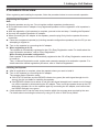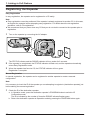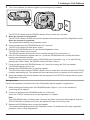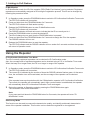
1
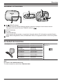
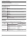
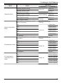
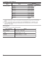
Installation Manual
DECT Repeater
Model No.
KX-A406
Thank you for purchasing this Panasonic product.
Please read this manual carefully before using this product and save this manual for future
use.
Note
R In this manual, the suffix of each model number is omitted unless necessary.
Document Version: 2015-02
Introduction
Introduction
Outline
This manual describes information about the installation and registration of KX-A406.
Related Documentation
R Quick Start Guide
Describes setup and safety information of the unit.
Manuals and supporting information are provided on the Panasonic Web site at:
http://panasonic.net/pcc/support/pbx/
Note
The contents and design of the software are subject to change without notice.
About this Installation Manual
This Installation Manual is designed to serve as an overall installation reference when using this repeater
with Panasonic Cell Stations/Portable Stations, Panasonic SIP Cordless Phones, and Panasonic Digital
Cordless Phones.
The SIP Cordless Phone base unit and the Digital Cordless Phone base unit are described as base unit
in this manual.
This manual contains the following sections:
1. Linking to Cell Stations
Details the procedure for using the repeater with Panasonic Cell Stations and Portable Stations.
2. Linking to SIP Cordless Phones
Details the procedure for using the repeater with Panasonic SIP Cordless Phones.
3. Linking to Digital Cordless Phones
Details the procedure for using the repeater with Panasonic Digital Cordless Phones.
2
Table of Contents
Important Information
Important Information ..........................................4
For best performance .........................................7
Overview
Overview .............................................................9
System Connection Example ..............................9
Location of Controls ..........................................11
Included Accessories ........................................11
1. Linking to Cell Stations
Linking to Cell Stations .....................................12
Compatible Devices ..........................................12
Indicators ..........................................................12
Procedure Overview .........................................15
Registering the Repeater ..................................16
Using the Repeater ...........................................18
Troubleshooting ................................................19
2. Linking to SIP Cordless Phones
Linking to SIP Cordless Phones .......................22
Compatible Devices ..........................................22
Indicators ..........................................................22
Installation/Registering the Repeater ................23
Troubleshooting ................................................24
3. Linking to Digital Cordless Phones
Linking to Digital Cordless Phones (except for
North America) ..................................................26
Indicators ..........................................................26
Installation/Registering the Repeater ................26
Troubleshooting ................................................28
Appendix
Appendix ...........................................................29
Wall Mounting ...................................................29
Specifications ....................................................31
3
Important Information
Important Information
CAUTION
SECURITY REQUIREMENTS
Preventing Data Disclosure Over the Network
R To ensure the security of private conversations, only connect the product to a secure network.
R To prevent unauthorized access, only connect the product to a network that is properly managed.
Note
SAFETY REQUIREMENTS
R Before connecting the product, confirm that the product supports the intended operating environment.
R If the product does not operate properly, disconnect the AC adaptor cord, then connect again.
R The product may not operate in the event of a power failure.
R Satisfactory operation, interoperability, and compatibility cannot be guaranteed with all equipment
connected to the product, nor with all services provided by telecommunications providers over
networks connected to the product.
SECURITY REQUIREMENTS
R Privacy of communications may not be ensured when using the wireless systems.
4
Important Information
Information for Users on Collection and Disposal of Old Equipment and used Batteries
These symbols on the products, packaging, and/or accompanying
documents mean that used electrical and electronic products and batteries
should not be mixed with general household waste.
For proper treatment, recovery and recycling of old products and used
batteries, please take them to applicable collection points, in accordance
with your national legislation and the Directives 2002/96/EC and 2006/66/
EC.
By disposing of these products and batteries correctly, you will help to save
valuable resources and prevent any potential negative effects on human
health and the environment which could otherwise arise from inappropriate
waste handling.
For more information about collection and recycling of old products and
batteries, please contact your local municipality, your waste disposal
service or the point of sale where you purchased the items.
Penalties may be applicable for incorrect disposal of this waste, in
accordance with national legislation.
For business users in the European Union
If you wish to discard electrical and electronic equipment, please contact
your dealer or supplier for further information.
Information on Disposal in other Countries outside the European Union
These symbols are only valid in the European Union. If you wish to discard
these items, please contact your local authorities or dealer and ask for the
correct method of disposal.
Note for the battery symbol (bottom two symbol examples):
This symbol might be used in combination with a chemical symbol. In this
case it complies with the requirement set by the Directive for the chemical
involved.
5
Important Information
For Users in European countries
The following declaration is applicable to KX-A406CE/KX-A406UK only
Panasonic System Networks Co., Ltd. declares that this equipment is in compliance with the essential
requirements and other relevant provisions of Radio & Telecommunications Terminal Equipment
(R&TTE) Directive 1999/5/EC.
Declarations of Conformity for the relevant Panasonic products described in this manual are available for
download by visiting:
http://www.ptc.panasonic.eu
Contact to Authorized Representative:
Panasonic Testing Center
Panasonic Marketing Europe GmbH
Winsbergring 15, 22525 Hamburg, Germany
Ecodesign information
Ecodesign information under EU Regulation (EC) No.1275/2008 amended by (EU) Regulation No.
801/2013.
=======================================
Please visit here: www.ptc.panasonic.eu
click [Downloads]
® Energy related products information (Public)
=======================================
Power consumption in networked standby and guidance are mentioned in the web site above.
For Users in the United States Only
FCC and Other Information
Privacy of communications may not be ensured when using this product.
FCC RF Exposure Warning
R This product complies with FCC radiation exposure limits set forth for an uncontrolled environment.
R To comply with FCC RF exposure requirements, the product must be installed and operated 20 cm
(8 inches) or more between the product and all person’s body.
R This product may not be collocated or operated in conjunction with any other antenna or transmitter.
FCC ID can be found on the back of this product.
Note
This equipment has been tested and found to comply with the limits for a Class B digital device, pursuant
to Part 15 of the FCC Rules. These limits are designed to provide reasonable protection against harmful
interference in a residential installation. This equipment generates, uses, and can radiate radio frequency
energy and, if not installed and used in accordance with the instructions, may cause harmful interference
to radio communications. However, there is no guarantee that interference will not occur in a particular
installation. If this equipment does cause harmful interference to radio or television reception, which can
be determined by turning the equipment off and on, the user is encouraged to try to correct the
interference by one or more of the following measures:
R Reorient or relocate the receiving antenna.
R Increase the distance between the equipment and receiver.
6
Important Information
R Connect the equipment to an outlet on a circuit different from that to which the receiver is connected.
R Consult the dealer or an experienced radio/TV technician for help.
This device complies with Part 15 of the FCC Rules. Operation is subject to the following two conditions:
(1) this device may not cause harmful interference, and (2) this device must accept any interference
received, including interference that may cause undesired operation.
CAUTION
Any changes or modifications not expressly approved by the party responsible for compliance could void
the user’s authority to operate this product.
For Users in Canada Only
Industry Canada Notices and Other Information
This product meets the applicable Industry Canada technical specifications.
Note
This device complies with Industry Canada licence-exempt RSS standard(s). Operation is subject to the
following two conditions: (1) this device may not cause interference, and (2) this device must accept any
interference, including interference that may cause undesired operation of the device.
Privacy of communications may not be ensured when using this product. Some wireless telephones
operate at frequencies that may cause interference to nearby TVs and VCRs. To minimize or prevent
such interference, the base of the wireless telephone should not be placed near, or on top of, a TV or
VCR.
This will often reduce, or eliminate, interference.
This Class B digital apparatus complies with Canadian ICES-003.
CAUTION
Any changes or modifications not expressly approved by the party responsible for compliance could void
the user’s authority to operate this product.
RF Exposure Warning
R This product complies with IC radiation exposure limits set forth for an uncontrolled environment.
R To comply with IC RF exposure requirements, the product must be installed and operated 20 cm
(8 inches) or more between the product and all person’s body.
R This product may not be collocated or operated in conjunction with any other antenna or transmitter.
For best performance
Repeater location/avoiding noise
The repeater and other compatible Panasonic products use radio waves to communicate with each other.
R For maximum coverage and noise-free communications, place your repeater:
– at a convenient, high, and central location with no obstructions between the PS/handset and
repeater in an indoor environment.
– away from electronic appliances such as TVs, radios, personal computers, wireless devices, or
other phones.
– facing away from radio frequency transmitters, such as external antennas of mobile phone cell
stations. (Avoid putting the repeater on a bay window or near a window.)
R Coverage and voice quality depends on the local environmental conditions.
R If the reception for a repeater location is not satisfactory, move the repeater to another location for
better reception.
7
Important Information
Environment
R Keep the repeater away from electrical noise generating devices, such as fluorescent lamps and
motors.
R The repeater should be kept free from excessive smoke, dust, high temperature, and vibration.
R The repeater should not be exposed to direct sunlight.
R Do not place heavy objects on top of the repeater.
R When you leave the repeater unused for a long period of time, unplug the repeater from the AC outlet.
R The repeater should be kept away from heat sources such as radiators, cookers, etc. It should not be
placed in rooms where the temperature is less than 0 °C (32 °F) or greater than 40 °C (104 °F). Damp
basements should also be avoided.
R The maximum calling distance may be shortened when the repeater is used in the following places:
Near obstacles such as hills, tunnels, underground, near metal objects such as wire fences, etc.
R Operating the repeater near electrical appliances may cause interference. Move away from the
electrical appliances.
R To prevent malfunction, deformity, overheating, rust, and discolouration, do not install or place
equipment in the following types of locations:
– Locations where air ventilation is poor.
– Locations that may be exposed to sulphurous gas, such as near hot springs.
– Near devices that emit heat, such as heaters.
– Near devices that emit electromagnetic noise, such as radios or televisions.
– Near devices that emit high-frequency noise, such as sewing machines or welders.
Routine care
R Wipe the outer surface of the repeater with a soft moist cloth.
R Do not use benzine, thinner, or any abrasive powder.
R Disconnect the AC adaptor cord from the product before cleaning. Clean the product with a soft, dry
cloth. Do not use liquid, aerosol cleaners, abrasive powders, or chemical agents to clean the product.
Placement
R Install the repeater within CS/base unit range in an indoor environment. We recommend installing the
repeater in a raised position (such as on a wall).
R Avoid positioning the repeater close to objects that will interfere with reception, such as thick walls,
radiators, metal shelving, etc.
R For maximum distance noise-free operation, place the repeater away from electrical appliances such
as TV, radio, personal computer, or other telephone equipment.
R Keep an appropriate distance from the CS/base unit to maximize the range of your phone system.
Find the appropriate location by checking the RSSI*1/ID indicator. If the RSSI/ID indicator turns red or
amber, re-position the repeater in a place where the RSSI/ID indicator turns green.
For details about the RSSI/ID indicator, refer to the following pages.
When using the repeater with
– Cell Stations: refer to "Indicators (Page 12)",
– SIP Cordless Phones: refer to "Indicators (Page 22)", and
– Digital Cordless Phones: refer to "Indicators (Page 26)".
*1 RSSI: Received Signal Strength Indication
8
Overview
Overview
A repeater is used when you need to extend the range of a handset or a DECT Portable Station (PS) or a
SIP/Digital handset to include areas where reception was previously not available. The repeater extends
the range in all directions, allowing several floors to be covered.
Up to 6 repeaters can be registered to one Cell Station (CS) and up to 2 repeaters can be registered to
one base unit. Also, up to 3 repeaters can be arranged in a cascade configuration.*1
*1 Cascade connections are not available when connecting with KX-TGP500 or KX-TGP550 base units.
Note
R You must register the repeater with your CS/base unit before it can be used.
System Connection Example
Example: Connecting CSs and PSs
PBX
A
: PBX
: KX-A406
: CS
: PS
A : Cascade configuration
9
Overview
Repeater Coverage Area
As a guideline, the example below shows the size of the coverage area where one repeater can
synchronize with a CS/base unit/destination repeater, or provide coverage for a PS/handset, if it is
installed in an area with no obstacles.
Note
R The distance may vary depending on the environment.
R If the repeater’s STATUS indicator and RSSI/ID indicator turn green (the radio signal strength level is
strong) after turning on the repeater, the site is suitable for installing the repeater.
Base unit/handset
CS/PS
B
A
: KX-A406
B
A
: CS
: Base unit
A
Repeater coverage area for synchronization between CS/base unit/destination repeater
and repeater.
Maximum Distance: 40 m to 50 m (98 ft to 131 ft)
B
Repeater coverage area for PS/handset.
Maximum Distance: 50 m to 60 m (131 ft to 164 ft)
10
Overview
Location of Controls
D
C
E
A
B
RSSI/ID Indicator
The RSSI (Received Signal Strength Indicator) shows the strength of the wireless network.
Throughout this manual, the term "RSSI/ID" refers to
.
STATUS Indicator
DC Jack
PROGRAM Button
Used to power off the repeater, or to switch to Operation Mode, ID Confirmation mode/Verification
mode, Manual Registration mode, ID Modification Mode, De-registration Mode or Site Survey Mode.
Hook
Included Accessories
AC adaptor: 1
Model No.
Part No.
KX-A406
PQLV219
KX-A406UK
PQLV219E
KX-A406CE
PQLV219CE
KX-A406AL
PQLV219AL
KX-A406LC
PQLV219BX
KX-A406LA
PQLV219
Screws: 2
Washers: 2
Note
For users in the United States only
To order accessories, call toll-free 1-800-322-5368.
11
1. Linking to Cell Stations
Linking to Cell Stations
This section describes how to use the repeater to connect CSs and PSs.
Compatible Devices
The United States Only
Compatible Device
Model No.
CS
KX-T0155, KX-T0158, KX-TDA0156, KX-NCP0158, KX-NS0154
Canada Only
Compatible Device
Model No.
CS
KX-TDA0155, KX-TDA0156, KX-TDA0158, KX-NCP0158, KX-NS0154
Central and South America Only
Compatible Device
Model No.
CS
KX-TDA0155
All Other Countries/Areas
Compatible Device
Model No.
CS
KX-TDA0141, KX-TDA0142, KX-TDA0155, KX-TDA0156, KX-TDA0158,
KX-NCP0158, KX-NS0154
Indicators
The indicator patterns and the corresponding status of the repeater in each mode are as follows. For
details about each mode, refer to "Registering the Repeater" or "Using the Repeater".
Mode
—
De-registration Mode
Registration Mode
(Easy/Manual)
12
Indicators
Status
STATUS
Power Off
Off
Entering De-registration mode (0–5
seconds*1)
Red Flashing
Entering De-registration mode (5–10
seconds*1)
Quick Red
Flashing
De-registration complete (after 10
seconds*1)
Red On
Searching for devices
Red Flashing
RSSI/ID
Off
Off
Off
1. Linking to Cell Stations
Mode
Status
Standby (signal is strong)
Standby (signal is weak)
Standby (out of range)
Operation Mode
Talking (signal is strong)
Talking (signal is weak)
Busy (signal is strong)
Manual Registration
Mode
Red On
Green Flashing
Quick Green
Flashing
Entering Manual Registration Mode
(after 5 seconds*2)
Quick Green
Flashing
RSSI/ID
Green On
Amber On
Red On
Green On
Amber On
Green On
Amber On
Off
ID1
1 Red Flash
ID2
2 Red Flashes
ID3
ID4
3 Red Flashes
Green On
4 Red Flashes
ID5
5 Red Flashes
ID6
6 Red Flashes
ID assigned
Red On
Quick Amber
Flashing
Off
ID1
1 Red Flash
ID2
2 Red Flashes
ID3
ID4
ID Confirmation/
Verification Tone
Mode
Green On
Busy (signal is weak)
Entering ID Modification Mode (after 5
seconds*3)
ID Modification Mode
Indicators
STATUS
3 Red Flashes
Amber On
4 Red Flashes
ID5
5 Red Flashes
ID6
6 Red Flashes
ID assigned
Red On
ID1
1 Green Flash
ID2
2 Green Flashes
ID3
ID4
Amber On
3 Green Flashes
4 Green Flashes
ID5
5 Green Flashes
ID6
6 Green Flashes
13
1. Linking to Cell Stations
Mode
Indicators
Status
Site Survey Mode
STATUS
Channel 1
1 Green Flash
Channel 2
2 Green Flashes
Channel 3
3 Green Flashes
Channel 4
4 Green Flashes
Channel 5
5 Green Flashes
Channel 6
6 Green Flashes
Channel 7
7 Green Flashes
Channel 8
8 Green Flashes
Channel 9
9 Green Flashes
Channel 0
10 Green
Flashes
RSSI/ID
Off
*1 The time elapsed after turning on the repeater while pressing and holding down the PROGRAM
button.
*2 The time elapsed after pressing and holding down the PROGRAM button in Operation mode.
*3 The time elapsed after pressing and holding down the PROGRAM button in ID Confirmation/
Verification Tone mode.
Flashing Speeds
Indicators flash in a cycle at the following speeds:
Type of Flashing
Speed
Regular Flashing
640 ms On ® 640 ms Off
Quick Flashing
320 ms On ® 320 ms Off
1 Flash
Regular Flashing ® 3 s Off
2 Flashes
Regular Flashing ´ 2 ® 3 s Off
Regular Flashing ´ 3 ® 3 s Off
3 Flashes
:
14
:
1. Linking to Cell Stations
Procedure Overview
When registering and installing the repeater, follow the procedure below to ensure smooth operation.
Registering the Repeater
Note
R Register repeaters one by one. Do not register multiple repeaters simultaneously.
R Do not disconnect the AC adaptor of any registered repeaters until the registration of all repeaters is
complete.
R After the registration of all repeaters is complete, proceed to the next step—"Installing the Repeater".
R Use only the supplied Panasonic AC adaptor.
R When connecting the AC adaptor to the repeater, press the plug firmly into the repeater for secure
connection.
a.
Place the unregistered repeater(s) (including cascade configuration repeaters) near the CS you are
attempting to register to.
b.
c.
Turn on the repeater by connecting the AC adaptor.
When registering to a CS:
The repeater is automatically registered to the CS in Easy Registration mode. For details about the
easy registration procedure, refer to "Easy Registration".
When creating a cascade configuration:
Each repeater in the cascade is automatically registered to the CS in Easy Registration mode when it
is turned on.
Then, in Manual Registration mode, register each cascade repeater to its destination repeater. For
details about the manual registration procedure, refer to "Manual Registration".
Installing the Repeater
a.
b.
After all registration is complete, place the repeater where you want to install it.
c.
Check whether the PS can be used at any location within the coverage area required by the user.
For details about conducting the site survey using a PS, refer to "Site Survey Mode".
Turn on the repeater by connecting the AC adaptor.
The repeater enters Operation mode.
R If the STATUS indicator and the RSSI/ID indicator turn green (the radio signal strength level is
strong), the site is suitable for installing the repeater.
R If the RSSI/ID indicator turns amber or red (the radio signal strength level is weak or out of range),
turn off the repeater by disconnecting the AC adaptor. Then, move the repeater closer to the CS/
destination repeater, turn on the repeater again by connecting the AC adaptor, and confirm that
the RSSI/ID indicator turns green.
15
1. Linking to Cell Stations
Registering the Repeater
Easy Registration
In easy registration, the repeater can be registered to a CS easily.
Note
R Easy registration cannot be performed if the repeater is already registered to another CS. In this case,
de-register the repeater before attempting easy registration. For details about the de-registration
procedure, refer to "De-registration".
R We recommend that you power down any CS that you do not wish to connect to the repeater prior to
registration.
1
Turn on the repeater by connecting the AC adaptor.
The STATUS indicator and the RSSI/ID indicator will turn amber for 2 seconds.
2
If the repeater is unregistered, the STATUS indicator will flash red, and the repeater automatically
enters Easy Registration mode.
3
When the repeater has found a CS, the STATUS indicator will turn green.
Registration is complete.
Manual Registration
In manual registration, the repeater can be registered to another repeater to create a cascade
configuration.
Note
It is necessary to check the ID of the repeater you are attempting to register to (destination repeater) just
before starting the manual registration.
1
16
Check the ID of the destination repeater.
a. In Operation mode, press the destination repeater’s PROGRAM button to switch to ID
Confirmation mode.
The ID is indicated by the number of times the RSSI/ID indicator flashes green.
b. Return the destination repeater to Operation mode by pressing the PROGRAM button again.
1. Linking to Cell Stations
2
Turn on the repeater you want to register by connecting the AC adaptor.
The STATUS indicator and the RSSI/ID indicator will turn amber for 2 seconds.
3
When the repeater is unregistered:
The STATUS indicator will flash red, and the repeater automatically enters Easy Registration mode.
When the repeater is registered:
The repeater automatically enters Operation mode.
4
Press and hold down the PROGRAM button for 5 seconds.
The STATUS indicator will flash green quickly.
5
Release the PROGRAM button to enter Manual Registration mode.
The STATUS indicator will turn green.
The RSSI/ID indicator will flash red once to indicate that the ID is currently set to 1.
6
If the ID of the destination repeater was not 1, press the PROGRAM button to select the ID that
matches the destination repeater.
The ID will change by one each time the PROGRAM button is pressed. (e.g., If you select ID3 by
pressing the button 2 times, the RSSI/ID indicator will flash 3 times.)
7
Press and hold down the PROGRAM button for 5 seconds to assign the ID to the repeater.
The RSSI/ID indicator will turn red.
8
Release the PROGRAM button to reset the repeater.
The STATUS indicator and the RSSI/ID indicator will turn amber for 2 seconds and then the STATUS
indicator start flashing red. The repeater will then start searching for a repeater with the assigned ID.
9
When the repeater has found a repeater with the assigned ID, the STATUS indicator will turn green.
Registration is complete.
De-registration
Perform de-registration to delete the ID of the CS/repeater that the repeater is registered to.
1
While pressing and holding down the PROGRAM button (Page 11), turn on the repeater by
connecting the AC adaptor.
2
Continue to hold down the PROGRAM button for 10 seconds.
When the STATUS indicator turns red, de-registration is complete.
Note
If the PROGRAM button is released after 5 seconds but before 10 seconds have elapsed, while the
STATUS indicator is flashing red quickly, the repeater will enter Site Survey mode.
3
Release the PROGRAM button to reset the repeater.
The repeater automatically enters Easy Registration mode. For details about the easy registration
procedure, refer to "Easy Registration".
17
1. Linking to Cell Stations
ID Modification
In ID Modification mode, the ID of the repeater (RPN [Radio Part Number]) can be selected. Registered
repeaters are automatically assigned an ID during the registration process. This ID can be changed by
following the procedure below.
1
In Operation mode, press the PROGRAM button to switch to ID Confirmation/Verification Tone mode.
The STATUS indicator will turn amber.
2
Press and hold down the PROGRAM button for 5 seconds.
The STATUS indicator will flash amber quickly.
3
Release the PROGRAM button to enter ID Modification mode.
The STATUS indicator will turn amber.
The RSSI/ID indicator will flash red once to indicate that the ID is currently set to 1.
4
Press the PROGRAM button to select the desired ID.
The ID will change by one each time the PROGRAM button is pressed.
5
Press and hold down the PROGRAM button for 5 seconds to assign the ID to the repeater.
The RSSI/ID indicator will turn red.
6
Release the PROGRAM button to reset the repeater.
The STATUS indicator and the RSSI/ID indicator will turn amber for 2 seconds and then the repeater
will return to Operation mode.
Using the Repeater
ID Confirmation/Verification Tone Mode
The ID of currently registered repeaters can be checked in ID Confirmation mode.
Also, the coverage area of registered repeaters can be checked using a PS, in Verification Tone mode.
When the beep is no longer heard, the PS is no longer in range of the repeater.
1
In Operation mode, press the PROGRAM button to switch to ID Confirmation/Verification Tone mode.
The STATUS indicator will turn amber.
2
The current ID is indicated by the number of times the RSSI/ID indicator flashes green. At the same
time, the verification tone will be activated, and the coverage of the repeater can be checked.
Note
If the repeater loses synchronization with the CS/destination repeater in ID Confirmation/Verification
Tone mode, the repeater will automatically reset. After synchronization is established, the repeater
will automatically enter ID Confirmation/Verification Tone mode again.
3
Return the repeater to Operation mode by pressing the PROGRAM button again.
The verification tone will be deactivated.
Note
If you press and hold down the PROGRAM button for 5 seconds, the repeater will enter "ID
Modification" mode.
Site Survey Mode
This function can be used to measure the transmission quality, and identify problematic transmission
areas of the repeater installation. This function can be used when registered or de-registered.
18
1. Linking to Cell Stations
Note
R The repeater’s Site Survey mode works independently from the CS. This means that the CS does not
have to be placed into Site Survey mode.
R When using more than 1 repeater in Site Survey mode simultaneously, please ensure repeaters are
set to different channels.
1
While pressing and holding down the PROGRAM button, turn on the repeater by connecting the AC
adaptor.
The STATUS indicator will flash red.
2
Continue to hold down the PROGRAM button for 5 seconds.
The STATUS indicator will flash red quickly.
Note
If you continue to hold down the PROGRAM button for 10 seconds, the repeater will enter
De-registration mode.
3
Release the PROGRAM button.
The STATUS indicator will flash red to indicate the current channel number, and a carrier sense will
start to check whether the current channel is available (idle) or not.
4
If the current channel is available, the STATUS indicator will change to flash green.
Site Survey mode on the current channel is now operational.
Note
A carrier sense is performed regularly in Site Survey mode. If the selected channel is not available
(busy), the STATUS indicator will flash red to indicate the channel number and the repeater will stop
transmitting.
5
Activate the site survey function on the PS to measure the radio signal strength level. The repeater
CSID is 1234567890.
Note
R It is recommended that the radio signal strength level is "03" or greater.
R For details about using the PS during a site survey, refer to the appropriate documentation for the
CS.
6
To change the site survey channel, press the PROGRAM button.
The channel number will change by one each time the PROGRAM button is pressed.
7
To turn off Site Survey mode, turn off the repeater by disconnecting the AC adaptor, and then turn on
the repeater by connecting the AC adaptor.
Troubleshooting
PROBLEM
R The repeater does
not turn on.
PROBABLE CAUSE
R The AC adaptor is not
connected properly.
SOLUTION
R Make sure that the AC adaptor is properly
connected to both the repeater and the AC
outlet.
19
1. Linking to Cell Stations
PROBLEM
PROBABLE CAUSE
SOLUTION
R The CS is out of range.
R The repeater
cannot be
R The CS is not turned on.
registered in Easy
Registration mode.
(The process keeps
repeating
automatically.)
R Move the repeater closer to the CS.
R The repeater
R The destination repeater is
cannot be
not turned on.
registered in
R The selected ID does not
Manual
match the ID of the
Registration mode.
destination repeater.
(The process keeps
repeating
automatically.)
R Confirm that the destination repeater is on.
R Confirm that the CS is on.
R Follow the procedure below to change the
selected ID.
1. Check the ID of the destination
repeater in ID Confirmation mode (refer
to "ID Confirmation/Verification Tone
Mode").
2. Enter Manual Registration mode by
pressing and holding down the
PROGRAM button of the repeater for 5
seconds while the repeater’s STATUS
indicator is flashing red, and releasing it.
3. Select the ID that matches the
destination repeater in manual
registration again (refer to "Manual
Registration").
R The repeater’s
STATUS indicator
and RSSI/ID
indicator flash
green and red
alternately (alarm
indication).
R The ID of the repeater is the R Follow the procedure below to change the
same as the ID of another
ID of the repeater.
repeater (including cascade
1. Press the PROGRAM button to cancel
configuration repeaters)
the alarm indication of the repeater.
that is registered to the
The repeater will enter ID Confirmation
same CS.
mode.
2. Check the IDs of the repeater and the
other repeater that is registered to the
same CS, in ID Confirmation mode
(refer to "ID Confirmation/Verification
Tone Mode").
3. Enter ID Modification mode by pressing
and holding down the PROGRAM
button of the repeater for 5 seconds
and releasing it.
4. Change the ID of the repeater so as
not to overlap with the ID of the other
repeater in ID Modification mode (refer
to "ID Modification").
R The PS is beeping.
R The verification tone is
turned on.
R Turn the verification tone off (refer to "ID
Confirmation/Verification Tone Mode").
R Poor audio quality.
R The CS is out of range.
R Move the repeater closer to the CS.
R The PS is out of range.
R Move the PS closer to the repeater.
20
1. Linking to Cell Stations
PROBLEM
R A ringing call
suddenly stops
when moving
between CS/
repeater zones.
PROBABLE CAUSE
SOLUTION
R There is a delay when
R Answer the call before moving between
moving from a CS zone to a
CS/repeater zones.
repeater zone when
receiving a call in group ring
mode.
R The new zone is "busy", so
R When talking and
moving between
handover cannot occur.
zones, you hear an
alarm or continuous
noise, or your call is
disconnected.
R Return to the original zone and continue
your call.
21
2. Linking to SIP Cordless Phones
Linking to SIP Cordless Phones
This section describes how to use the repeater to connect SIP cordless phone base units and handsets.
Compatible Devices
The United States, Canada, Central and South America
Compatible Device
Model No.
Base unit
KX-TGP600
All Other Countries/Areas
Compatible Device
Model No.
Base unit
KX-TGP500, KX-TGP550, KX-TGP600
Indicators
Indicators
STATUS
Light Status
Green
Red
R Within base unit range. The repeater is ready for use.
Flashing
R 1 handset is communicating with the base unit through
the repeater.
Quick
Flashing
R 2 handsets are communicating with the base unit
through the repeater.
On
R Out of base unit range.
Flashing
R The repeater is not registered to the base unit.
R The power is off. (AC adaptor is not connected
properly.)
Off
RSSI/ID
On
R Signal strength of the base unit is strong.
Flashing
R The number of times the RSSI/ID indicator flashes
indicates the current ID of registered repeaters. When
it flashes green once, it indicates that the ID is
currently set to 1.
R The base unit is in repeater range.
Amber
On
R Signal strength of the base unit is weak.
Red
On
R Out of base unit range.
R The ID has been registered to the repeater.
Flashing
R The number of times the RSSI/ID indicator flashes
indicates the ID that will be registered to the repeater.
When it flashes red once, it indicates that the ID will be
set to 1.
Green
Off
22
Meaning
On
R The repeater is not being used.
R The power is off.
2. Linking to SIP Cordless Phones
Installation/Registering the Repeater
Once the repeater is connected to an AC outlet, it automatically goes into registration mode (if not
already registered).
IMPORTANT
R Before registering the repeater to the base unit, you must turn the repeater mode on. Refer to the
appropriate documentation for the base unit.
R If the repeater is already registered, deregister the repeater first, then re-register it. For registering and
deregistering the repeater, refer to "Deregister" and "Re-register" in "Troubleshooting".
Note
R Use only the supplied Panasonic AC adaptor.
R When connecting the AC adaptor to the repeater, press the plug firmly into the repeater for secure
connection.
1
Repeater: Connect the AC adaptor.
2
Base unit: Press and hold the Handset locator button for about 4 seconds until the STATUS
indicator flashes red.
R The button and indicator depend on the base unit.
R If all registered handsets start ringing, press the same button to stop. Then repeat this step.
R The next step must be completed within 90 seconds.
3
Repeater: Connect the AC adaptor to an AC outlet.
R When the repeater is turned on, the STATUS indicator and RSSI/ID indicator turn amber for about
2 seconds.
4
Repeater: Wait until the STATUS indicator and RSSI/ID indicator turn green. (The repeater is
ready for use.)
R If the indicators do not turn green, re-position the repeater in a place where the indicators turn
green.
5
Base unit: To exit registration mode, press the Handset locator button.
R The button depends on the base unit.
23
2. Linking to SIP Cordless Phones
Note
R The AC adaptor must remain connected at all times. (It is normal for the adaptor to feel warm during
use.)
R The repeater can support a maximum of 4 calls at a time.
R When the STATUS indicator flashes green rapidly, a handset registered to the repeater cannot make/
receive a call through the repeater. Neither can a handset during a conversation within the base unit
range switch to the repeater range.
R Do not use more than 2 repeaters at a time.
R Cascade connections are not available when connecting with KX-TGP500 or KX-TGP550 base units.
R The following limitations apply when the KX-A406 (repeater) is connected to a KX-TGP600 base unit.
– Narrowband mode:
Up to 3 KX-A406 units can be connected in a cascade configuration, and up to 4 calls can be made
simultaneously.
– Wideband mode:
Up to 2 KX-A406 units can be connected in a cascade configuration, and up to 2 calls can be made
simultaneously.
Troubleshooting
Problem
The repeater does not work.
Cause/solution
R When the indicators do not turn on, the AC adaptor is not
connected properly. Check the connections.
R When the indicators do not turn green, move the repeater
closer to the base unit.
R Registration may have been canceled.
Deregister the repeater, then re-register.
Deregister
1
Unplug the AC adaptor, then press and hold the
PROGRAM button.
2
While pressing and holding the PROGRAM button,
re-connect the AC adaptor.
3
Keep pressing and holding the PROGRAM button for
about 10 seconds until the STATUS indicator stops
flashing and RSSI/ID indicator turns red. Then release
the PROGRAM button.
R The STATUS indicator and the RSSI/ID indicator turn
amber for about 2 seconds and the STATUS indicator
flashes red again.
R If the STATUS indicator flashes green after releasing the
PROGRAM button, deregistration failed. Deregister the
repeater again.
Re-register
Unplug the AC adaptor, then perform from step 2 of
“Installation/Registering the Repeater”.
While talking using the handset, sound R The handset is out of range. Move the handset closer to
cuts in and out.
the repeater.
24
2. Linking to SIP Cordless Phones
Problem
Cause/solution
A repeating tone is heard while talking
using the handset.
or
The STATUS indicator is amber and
the RSSI/ID indicator flashes green.
R The PROGRAM button was pressed. The repeater is in
programming mode. To exit, press the PROGRAM button
again. Do not press the PROGRAM button, except when
deregistering the repeater.
The repeater’s STATUS indicator and
RSSI/ID indicator flash green and red
alternately (alarm indication).
R The ID of the repeater is the same as the ID of another
repeater that is registered to the same base unit.
Deregister both of the repeaters, then re-register them near
the base unit.
Deregister
1
Unplug the AC adaptor, then press and hold the
PROGRAM button.
2
While pressing and holding the PROGRAM button,
re-connect the AC adaptor.
3
Keep pressing and holding the PROGRAM button for
about 10 seconds until the STATUS indicator stops
flashing and RSSI/ID indicator turns red. Then release
the PROGRAM button.
R The STATUS indicator and the RSSI/ID indicator turn
amber for about 2 seconds and the STATUS indicator
flashes red again.
R If the STATUS indicator flashes green after releasing the
PROGRAM button, deregistration failed. Deregister the
repeater again.
Re-register
Unplug the AC adaptor, then perform from step 2 of
“Installation/Registering the Repeater”.
The handset registered to the repeater R When the STATUS indicator flashes green rapidly, a
cannot make/receive a call.
handset registered to the repeater cannot make/receive a
call through the repeater. Move closer to the base unit or
wait until the STATUS indicator flashes slowly or the
STATUS indicator is on.
25
3. Linking to Digital Cordless Phones
Linking to Digital Cordless Phones (except for North
America)
This section describes how to use the repeater to connect Panasonic Digital Cordless Phone base units
and handsets.
Indicators
Indicators
STATUS
Light Status
Green
Red
R Within base unit range. The repeater is ready for use.
Flashing
R Handsets are communicating with the base unit
through the repeater.
On
R Out of base unit range.
Flashing
R The repeater is not registered to the base unit.
R The power is off. (AC adaptor is not connected
properly.)
Off
RSSI/ID
Meaning
On
Green
On
R Signal strength of the base unit is strong.
Amber
On
R Signal strength of the base unit is weak.
Red
On
R Out of base unit range.
Off
R The repeater is not being used.
R The power is off.
Installation/Registering the Repeater
Once the repeater is connected to an AC outlet, it automatically goes into registration mode (if not
already registered).
IMPORTANT
R If the repeater is already registered, deregister the repeater first, then re-register it. For registering and
deregistering the repeater, refer to "Deregister" and "Re-register" in "Troubleshooting".
Note
R Use only the supplied Panasonic AC adaptor.
R When connecting the AC adaptor to the repeater, press the plug firmly into the repeater for secure
connection.
26
3. Linking to Digital Cordless Phones
1
Repeater: Connect the AC adaptor.
2
Base unit: Press and hold the Handset locator button for about 5 seconds.
R If all registered handsets start ringing, press the same button to stop. Then repeat this step.
R The next step must be completed within 90 seconds.
3
Repeater: Connect the AC adaptor to an AC outlet.
R When the repeater is turned on, the STATUS indicator and RSSI/ID indicator turn amber for about
2 seconds.
4
Repeater: Wait until the STATUS indicator and RSSI/ID indicator turn green. (The repeater is
ready for use.)
R If the indicators do not turn green, re-position the repeater in a place where the indicators turn
green.
5
Base unit: To exit registration mode, press the Handset locator button.
R The button depends on the base unit.
Note
R The AC adaptor must remain connected at all times. (It is normal for the adaptor to feel warm during
use.)
R The repeater can support a maximum of 4 calls at a time.
R Do not use more than 2 repeaters at a time.
27
3. Linking to Digital Cordless Phones
Troubleshooting
Problem
The repeater does not work.
Cause/solution
R When the indicators do not turn on, the AC adaptor is not
connected properly. Check the connections.
R When the indicators do not turn green, move the repeater
closer to the base unit.
R Registration may have been canceled.
Deregister the repeater, then re-register.
Deregister
1
Unplug the AC adaptor, then press and hold the
PROGRAM button.
2
While pressing and holding the PROGRAM button,
re-connect the AC adaptor.
3
Keep pressing and holding the PROGRAM button for
about 10 seconds until the STATUS indicator stops
flashing and RSSI/ID indicator turns red. Then release
the PROGRAM button.
R The STATUS indicator and the RSSI/ID indicator turn
amber for about 2 seconds and the STATUS indicator
flashes red again.
R If the STATUS indicator flashes green after releasing the
PROGRAM button, deregistration failed. Deregister the
repeater again.
Re-register
Unplug the AC adaptor, then perform from step 2 of
“Installation/Registering the Repeater”.
While talking using the handset, sound R The handset is out of range. Move the handset closer to
cuts in and out.
the repeater.
A repeating tone is heard while talking
using the handset.
or
The STATUS indicator is amber and
the RSSI/ID indicator flashes green.
28
R The PROGRAM button was pressed. The repeater is in
programming mode. To exit, press the PROGRAM button
again. Do not press the PROGRAM button, except when
deregistering the repeater.
Appendix
Appendix
This section describes about mounting the repeater on a wall and its specifications.
Wall Mounting
Mounting
CAUTION
R Make sure the cable is securely fastened to the wall.
1
2
Place the reference for wall mounting on the wall to mark the 2 screw positions.
Install the 2 screws and washers (included) into the wall.
Note
R Make sure that the screw heads are at the same distance from the wall.
R Install the screws perpendicular to the wall.
3
Hook the repeater on the screw heads.
*1
*2
*1 Washer
*2 Drive the screw to this point.
29
Appendix
Reference for Wall Mounting
Print this page and use as a reference for wall mounting.
*1
37 mm
(1 15/32 in)
*1
*1 Install a screw here.
Note
Make sure to set the print size to correspond with the size of this page. If the dimension of the paper
output still deviates slightly from the measurement indicated here, use the measurement indicated here.
30
Appendix
Specifications
Basic Specifications
Maximum Number of Simultaneous Calls
4*1
Maximum Number of Cascade Steps
3*2
Maximum Number of Repeaters Registered to a CS/base unit
6*3
*1 The maximum number of simultaneous calls is 2 when connecting with KX-TGP500 or KX-TGP550
base units, or using wideband audio codec G.722 or G.722.2.
*2 Cascade connections are not available when connecting with KX-TGP500 or KX-TGP550 base units.
*3 The maximum number of repeaters is 2 when connecting with KX-TGP500 or KX-TGP550 base units.
Note
The maximum number of simultaneous calls may decrease depending on the wireless environment or
the PBX’s system configuration.
General Specifications
Dimensions
(Width ´ Depth ´ Height)
111 mm (W) ´ 39 mm (D) ´ 82 mm (H)
(4 3/8 in ´ 1 1/2 in ´ 3 1/4 in)
Weight
88 g (3.1 oz)
AC Adaptor
Input:
KX-A406/KX-A406LA
AC 100 V–120 V, 60 Hz
Power Supply
KX-A406CE/KX-A406UK/KX-A406AL/KX-A406LC
AC 220 V–240 V, 50 Hz/60 Hz
Output:
DC 6.5 V, 500 mA
Operating Temperature
0 °C to 40 °C ( 32 °F to 104 °F)
RF Specifications
Wireless Interface
DECT/DECT 6.0*1
Radio Access Method
MultiCarrier TDMA-TDD
Frequency Band
KX-A406CE/KX-A406UK/KX-A406AL
1880 MHz to 1900 MHz
KX-A406LC/KX-A406LA
1910 MHz to 1920 MHz
KX-A406
1920 MHz to 1930 MHz
Number of Carriers
KX-A406CE/KX-A406UK/KX-A406AL
10
KX-A406/KX-A406LA/KX-A406LC
5
31
Appendix
Carrier Spacing
1728 kHz
Bit Rate
1152 kbps
Modulation Scheme
GFSK
Transmission Output
KX-A406
Peak 115 mW
KX-A406CE/KX-A406UK/KX-A406AL/KX-A406LC/
KX-A406LA
Peak 250 mW
*1 The wireless interface differs according to the country/area.
32
Notes
33
Notes
34
Notes
35
1-62, 4-chome, Minoshima, Hakata-ku, Fukuoka 812-8531, Japan
http://www.panasonic.net/
Two Riverfront Plaza, Newark, NJ 07102-5490
http://www.panasonic.com/bts
5770 Ambler Drive, Mississauga, Ontario L4W 2T3
http://www.panasonic.ca
Copyright:
This material is copyrighted by Panasonic System Networks Co., Ltd., and may be reproduced for internal
use only. All other reproduction, in whole or in part, is prohibited without the written consent of Panasonic
System Networks Co., Ltd.
Panasonic System Networks Co., Ltd. 2015
PNQX6935ZA PP0215MK0