1
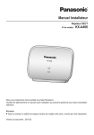
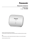
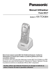
Installation Manual
DECT Repeater
Model No.
KX-A405
Thank you for purchasing a Panasonic DECT Repeater.
Please read this manual carefully before using this product and save this manual for future use.
Important Information
Important Information
SAVE THESE INSTRUCTIONS
Safety Notices
Please observe the safety notices in this manual in order to avoid danger to users or other people, and prevent
damage to property.
The notices are classified as follows, according to the severity of injury or damage:
WARNING
This notice means that misuse could result in death or serious injury.
CAUTION
This notice means that misuse could result in injury or damage to
property.
WARNING
SAFETY REQUIREMENTS
• The product must only be installed and serviced by qualified service personnel. The product should be
used as-is from the time of purchase; it should not be disassembled or modified. Disassembly or
modification can cause a fire, electric shock, or damage to the product.
• Make sure that the wall that the unit will be attached to is strong enough to support the unit (approx.
88 g). If not, it is necessary for the wall to be reinforced.
• Only use the wall-mounting equipment (screws, washers) included with the unit.
• When this unit is no longer in use, make sure to detach it from the wall.
• Do not connect or disconnect the AC plug with wet hands.
• Disconnect the unit from the AC outlet and contact the dealer if:
– The AC adaptor cord or AC plug becomes damaged or frayed.
– The unit is exposed to rain, water, or any other liquid.
– The unit is dropped or damaged.
– Internal components are exposed due to damage.
– The unit does not operate properly.
– Performance deteriorates.
• Disconnect the unit from the AC outlet if the unit emits smoke, an abnormal smell, or makes unusual
noise. These conditions can cause fire or electric shock. Confirm that smoke has stopped and contact
an authorised service centre.
• Clean the AC plug periodically with a soft, dry cloth to remove dust and other debris.
• Do not touch the unit or AC adaptor during a lightning storm.
• Use only the included AC adaptor (PQLV219).
• Do not allow anything to rest on the AC adaptor cord. Do not locate this unit where the AC adaptor
cord may be stepped on or tripped on.
CAUTION
SAFETY REQUIREMENTS
• The unit should be kept free of dust, moisture, high temperature (more than 40 °C), low temperature
(less than 0 °C), and vibration, and should not be exposed to direct sunlight.
• The unit should not be placed outdoors (use indoors).
• The unit should not be placed near high-voltage equipment.
• The unit should not be placed on a metal object.
2
Installation Manual
Important Information
•
•
•
•
•
•
•
•
•
•
When driving the screws into the wall, be careful to avoid touching any metal laths, wire laths or metal
plates in the wall.
To prevent malfunction, deformity, overheating, rust, and discolouration, do not install or place
equipment in the following types of locations:
– Locations where air ventilation is poor.
– Locations that may be exposed to sulphurous gas, such as near hot springs.
– Near devices that emit heat, such as heaters.
– Near devices that emit electromagnetic noise, such as radios or televisions.
– Near devices that emit high-frequency noise, such as sewing machines or welders.
Do not stretch or bend the cable. Also, do not allow anything to rest on the cable.
The unit and the cable should never be placed near or over a radiator or other heat source.
Do not bundle the cable that is connected to the unit with the AC power cords of machines located
nearby.
Make sure the cable is securely fastened to the wall.
The AC adaptor is used as the main disconnect device. Ensure that the AC adaptor is located near the
unit and is easily accessible.
Disconnect the AC adaptor cord from the unit before cleaning. Clean the unit with a soft, dry cloth. Do
not use liquid, aerosol cleaners, abrasive powders, or chemical agents to clean the unit.
When left unused for a long period of time, disconnect the unit from the AC outlet.
Medical—consult the manufacturer of any personal medical devices, such as pacemakers, to
determine if they are adequately shielded from external RF (radio frequency) energy. (The unit operates
in the frequency range of 1880 MHz to 1900 MHz, and the output peak power level is less than
0.25 W.) Do not use the unit in health care facilities if any regulations posted in the area instruct you
not to do so. Hospitals or health care facilities may be using equipment that could be sensitive to
external RF (radio frequency) energy.
SECURITY REQUIREMENTS
Preventing Data Disclosure Over the Network
• To ensure the security of private conversations, only connect the unit to a secure network.
• To prevent unauthorised access, only connect the unit to a network that is properly managed.
Notice
SAFETY REQUIREMENTS
• Before connecting the unit, confirm that the unit supports the intended operating environment.
• If the unit does not operate properly, disconnect the AC adaptor cord, then connect again.
• The unit may not operate in the event of a power failure.
• Satisfactory operation, interoperability, and compatibility cannot be guaranteed with all equipment
connected to the unit, nor with all services provided by telecommunications providers over networks
connected to the unit.
SECURITY REQUIREMENTS
Privacy of communications may not be ensured when using the wireless systems.
Note
In this manual, the suffix of each model number (e.g., KX-TDA0155CE) is omitted unless necessary.
Installation Manual
3
Important Information
Additional Information
For users in the European Union only
Information for Users on Collection and Disposal of Old Equipment and used Batteries
These symbols on the products, packaging, and/or accompanying documents mean that
used electrical and electronic products and batteries should not be mixed with general
household waste.
For proper treatment, recovery and recycling of old products and used batteries, please take
them to applicable collection points, in accordance with your national legislation and the
Directives 2002/96/EC and 2006/66/EC.
By disposing of these products and batteries correctly, you will help to save valuable
resources and prevent any potential negative effects on human health and the environment
which could otherwise arise from inappropriate waste handling.
For more information about collection and recycling of old products and batteries, please
contact your local municipality, your waste disposal service or the point of sale where you
purchased the items.
Penalties may be applicable for incorrect disposal of this waste, in accordance with national
legislation.
For business users in the European Union
If you wish to discard electrical and electronic equipment, please contact your dealer or
supplier for further information.
Information on Disposal in other Countries outside the European Union
These symbols are only valid in the European Union. If you wish to discard these items,
please contact your local authorities or dealer and ask for the correct method of disposal.
Note for the battery symbol (bottom two symbol examples):
This symbol might be used in combination with a chemical symbol. In this case it complies
with the requirement set by the Directive for the chemical involved.
4
Installation Manual
Table of Contents
Table of Contents
1 Overview ...................................................................................................6
System Overview ..............................................................................................................6
System Connection Example ...........................................................................................6
Names and Locations .......................................................................................................6
Unpacking ..........................................................................................................................7
LED Indications .................................................................................................................7
Compatible Devices ........................................................................................................10
Specifications ..................................................................................................................11
2 Procedure Overview ..............................................................................12
Registering the Repeater ................................................................................................12
Installing the Repeater ....................................................................................................13
3 Registering the Repeater .......................................................................14
Easy Registration ............................................................................................................14
Manual Registration ........................................................................................................15
De-registration .................................................................................................................16
ID Modification ................................................................................................................17
4 Using the Repeater ................................................................................18
ID Confirmation/Verification Tone Mode .......................................................................18
Site Survey Mode ............................................................................................................19
5 Wall Mounting .........................................................................................20
Mounting ..........................................................................................................................20
Reference for Wall Mounting .........................................................................................21
6 Troubleshooting .....................................................................................22
Installation Manual
5
1 Overview
1 Overview
System Overview
A repeater is used when you need to extend the range of a DECT Portable Station (PS) to include areas where
reception was previously not available. The repeater extends the range in all directions, allowing several floors
to be covered.
Up to 6 repeaters can be registered to one Cell Station (CS), and up to 3 repeaters can be arranged in a
cascade configuration.
System Connection Example
Note
The illustration of the PBX is based on the KX-NCP500.
PBX
Repeater
CS
Repeater
Cascade Configuration
Repeater
PS
Names and Locations
PROGRAM Button
DC Jack
STATUS LED
RSSI*1/ID LED
*1
6
RSSI: Received Signal Strength Indication
Installation Manual
Repeater
PS
1 Overview
Unpacking
Unpack the box and check the items below:
Repeater (KX-A405)
1
AC Adaptor (PQLV219)
1
Screws
2
Washers
2
LED Indications
The LED patterns and the corresponding status of the repeater in each mode are as follows. For details about
each mode, refer to "3 Registering the Repeater" or "4 Using the Repeater".
LED
Mode
Status
STATUS
—
De-registration Mode
Registration Mode
(Easy/Manual)
Power Off
Off
Entering De-registration
mode (0–5 seconds*1)
Red Flashing
Entering De-registration
mode (5–10 seconds*1)
Quick Red Flashing
De-registration complete
(after 10 seconds*1)
Red On
Searching for devices
Red Flashing
Standby (signal is strong)
Standby (signal is weak)
Standby (out of range)
Operation Mode
Talking (signal is strong)
Talking (signal is weak)
Busy (signal is strong)
Busy (signal is weak)
Green On
Red On
Green Flashing
Quick Green Flashing
RSSI/ID
Off
Off
Off
Green On
Amber On
Red On
Green On
Amber On
Green On
Amber On
Installation Manual
7
1 Overview
LED
Mode
Status
STATUS
Entering Manual Registration
Mode (after 5 seconds*2)
Manual Registration
Mode
1 Red Flash
ID2
2 Red Flashes
ID3
3 Red Flashes
ID4
8
Installation Manual
Green On
4 Red Flashes
ID5
5 Red Flashes
ID6
6 Red Flashes
ID assigned
Red On
Quick Amber Flashing
Off
ID1
1 Red Flash
ID2
2 Red Flashes
ID3
3 Red Flashes
ID4
ID Confirmation/
Verification Tone Mode
Off
ID1
Entering ID Modification
Mode (after 5 seconds*3)
ID Modification Mode
Quick Green Flashing
RSSI/ID
Amber On
4 Red Flashes
ID5
5 Red Flashes
ID6
6 Red Flashes
ID assigned
Red On
ID1
1 Green Flash
ID2
2 Green Flashes
ID3
ID4
Amber On
3 Green Flashes
4 Green Flashes
ID5
5 Green Flashes
ID6
6 Green Flashes
1 Overview
LED
Mode
Status
STATUS
Site Survey Mode*4
*1
*2
*3
*4
Channel 1
1 Green Flash
Channel 2
2 Green Flashes
Channel 3
3 Green Flashes
Channel 4
4 Green Flashes
Channel 5
5 Green Flashes
Channel 6
6 Green Flashes
Channel 7
7 Green Flashes
Channel 8
8 Green Flashes
Channel 9
9 Green Flashes
Channel 0
10 Green Flashes
RSSI/ID
Off
The time elapsed after turning on the repeater while pressing and holding down the PROGRAM button.
The time elapsed after pressing and holding down the PROGRAM button in Operation mode.
The time elapsed after pressing and holding down the PROGRAM button in ID Confirmation/Verification Tone mode.
For the KX-A405X, channels 0 and 1 cannot be used during a site survey.
Flashing Speeds
LEDs flash in a cycle at the following speeds:
Type of Flashing
Speed
Regular Flashing
640 ms On ® 640 ms Off
Quick Flashing
320 ms On ® 320 ms Off
1 Flash
Regular Flashing ® 3 s Off
2 Flashes
Regular Flashing ´ 2 ® 3 s Off
3 Flashes
Regular Flashing ´ 3 ® 3 s Off
:
:
Installation Manual
9
1 Overview
Compatible Devices
Compatible Device
*1
10
Model No.
CS
•
•
•
•
•
•
KX-TDA0141
KX-TDA0142
KX-TDA0155
KX-TDA0156
KX-TDA0158
KX-NCP0158 (IP-CS)
PS
•
•
•
•
•
•
•
KX-TCA155
KX-TCA175
KX-TCA256
KX-TCA275
KX-TCA355
KX-TCA364*1
KX-WT115
Not supported by the KX-A405X.
Installation Manual
1 Overview
Specifications
Basic Specifications
*1
Maximum Number of Simultaneous Calls
4*1
Maximum Number of Cascade Steps
3
Maximum Number of Repeaters Registered to a CS
6
The maximum number of simultaneous calls may decrease depending on the wireless environment or the PBX’s system configuration.
General Specifications
*1
Dimensions
111 mm (W) ´ 82 mm (H) ´ 39 mm (D)
Weight
88 g
Power Supply
AC Adaptor (PQLV219)
Input*1: AC 220 V–240 V, 50 Hz/60 Hz
Output: DC 6.5 V, 500 mA
Operating Temperature
0 °C to 40 °C
For the KX-A405X, the value is AC 100 V–120 V, 60 Hz.
RF Specifications
*1
*2
Wireless Interface
DECT
Radio Access Method
MultiCarrier TDMA-TDD
Frequency Band
1880 MHz to 1900 MHz*1
Number of Carriers
10*2
Carrier Spacing
1728 kHz
Bit Rate
1152 kbps
Modulation Scheme
GFSK
Transmission Output
Peak 250 mW
If the suffix of your PBX model is BX, TW, or XE, the value is 1880 MHz to 1895 MHz.
If the suffix of your PBX model is BX, TW, or XE, the value is 8.
Installation Manual
11
2 Procedure Overview
2 Procedure Overview
When registering and installing the repeater, follow the procedure below to ensure smooth operation.
Registering the Repeater
Note
•
•
•
Register repeaters one by one. Do not register multiple repeaters simultaneously.
Do not disconnect the AC adaptor of any registered repeaters until the registration of all repeaters is
complete.
After the registration of all repeaters is complete, proceed to the next step—"Installing the Repeater".
a. Place the unregistered repeater(s) (including cascade configuration repeaters) near the CS you are
attempting to register to.
b. Turn on the repeater by connecting the AC adaptor.
c. When registering to a CS:
The repeater is automatically registered to the CS in Easy Registration mode. For details about the easy
registration procedure, refer to "Easy Registration".
When creating a cascade configuration:
Each repeater in the cascade is automatically registered to the CS in Easy Registration mode when it is
turned on.
Then, in Manual Registration mode, register each cascade repeater to its destination repeater. For details
about the manual registration procedure, refer to "Manual Registration".
12
Installation Manual
2 Procedure Overview
Installing the Repeater
a. After all registration is complete, place the repeater where you want to install it.
Repeater Coverage Area
As a guideline, the example below shows the size of the coverage area where one repeater can
synchronise with a CS/destination repeater, or provide coverage for a PS, if it is installed in an area with
no obstacles.
Note
•
•
The distance may vary depending on the environment.
If the repeater’s STATUS LED and RSSI/ID LED turn green (the radio signal strength level is strong)
after turning on the repeater, the site is suitable for installing the repeater.
A Repeater Coverage Area for Synchronisation
between CS/Destination Repeater
Maximum Distance: 40 m to 50 m
B Repeater Coverage Area for Using PS
Maximum Distance: 50 m to 60 m
A
B
b. Turn on the repeater by connecting the AC adaptor.
The repeater enters Operation mode.
• If the STATUS LED and the RSSI/ID LED turn green (the radio signal strength level is strong), the site
is suitable for installing the repeater.
• If the RSSI/ID LED turns amber or red (the radio signal strength level is weak or out of range), turn off
the repeater by disconnecting the AC adaptor. Then, move the repeater closer to the CS/destination
repeater, turn on the repeater again by connecting the AC adaptor, and confirm that the RSSI/ID LED
turns green.
c. Check whether the PS can be used at any location within the coverage area required by the user. For
details about conducting the site survey using a PS, refer to "Site Survey Mode".
Installation Manual
13
3 Registering the Repeater
3 Registering the Repeater
Easy Registration
In easy registration, the repeater can be registered to a CS easily.
WARNING
•
•
When installing or testing a product with an external AC adaptor, the AC adaptor should be
plugged into a wall outlet or floor-mounted AC outlet. Do not connect the AC adaptor to a
ceiling-mounted AC outlet, as the weight of the adaptor may cause it to become disconnected.
Completely insert the AC adaptor/power plug into the AC outlet. Failure to do so may cause
electric shock and/or excessive heat resulting in a fire.
Note
•
•
Easy registration cannot be performed if the repeater is already registered to another CS. In this case,
de-register the repeater before attempting easy registration. For details about the de-registration
procedure, refer to "De-registration".
We recommend that you power down any CS that you do not wish to connect to the repeater prior to
registration.
1. Turn on the repeater by connecting the AC adaptor.
Hook
To AC Outlet
The STATUS LED and the RSSI/ID LED will turn amber for 2 seconds.
2. If the repeater is unregistered, the STATUS LED will flash red, and the repeater automatically enters Easy
Registration mode.
3. When the repeater has found a CS, the STATUS LED will turn green.
Registration is complete.
14
Installation Manual
3 Registering the Repeater
Manual Registration
In manual registration, the repeater can be registered to another repeater to create a cascade configuration.
WARNING
•
•
When installing or testing a product with an external AC adaptor, the AC adaptor should be
plugged into a wall outlet or floor-mounted AC outlet. Do not connect the AC adaptor to a
ceiling-mounted AC outlet, as the weight of the adaptor may cause it to become disconnected.
Completely insert the AC adaptor/power plug into the AC outlet. Failure to do so may cause
electric shock and/or excessive heat resulting in a fire.
Note
It is necessary to check the ID of the repeater you are attempting to register to (destination repeater) just
before starting the manual registration.
1. Check the ID of the destination repeater.
a. In Operation mode, press the destination repeater’s PROGRAM button to switch to ID Confirmation
mode.
The ID is indicated by the number of times the RSSI/ID LED flashes green.
b. Return the destination repeater to Operation mode by pressing the PROGRAM button again.
2. Turn on the repeater you want to register by connecting the AC adaptor.
Hook
To AC Outlet
The STATUS LED and the RSSI/ID LED will turn amber for 2 seconds.
3. When the repeater is unregistered:
4.
5.
6.
7.
8.
9.
The STATUS LED will flash red, and the repeater automatically enters Easy Registration mode.
When the repeater is registered:
The repeater automatically enters Operation mode.
Press and hold down the PROGRAM button for 5 seconds.
The STATUS LED will flash green quickly.
Release the PROGRAM button to enter Manual Registration mode.
The STATUS LED will turn green.
The RSSI/ID LED will flash red once to indicate that the ID is currently set to 1.
If the ID of the destination repeater was not 1, press the PROGRAM button to select the ID that matches
the destination repeater.
The ID will change by one each time the PROGRAM button is pressed. (e.g., If you select ID3 by pressing
the button 2 times, the RSSI/ID LED will flash 3 times.)
Press and hold down the PROGRAM button for 5 seconds to assign the ID to the repeater.
The RSSI/ID LED will turn red.
Release the PROGRAM button to reset the repeater.
The STATUS LED and the RSSI/ID LED will turn amber for 2 seconds and then the STATUS LED start
flashing red. The repeater will then start searching for a repeater with the assigned ID.
When the repeater has found a repeater with the assigned ID, the STATUS LED will turn green.
Registration is complete.
Installation Manual
15
3 Registering the Repeater
De-registration
Perform de-registration to delete the ID of the CS/repeater that the repeater is registered to.
WARNING
•
•
When installing or testing a product with an external AC adaptor, the AC adaptor should be
plugged into a wall outlet or floor-mounted AC outlet. Do not connect the AC adaptor to a
ceiling-mounted AC outlet, as the weight of the adaptor may cause it to become disconnected.
Completely insert the AC adaptor/power plug into the AC outlet. Failure to do so may cause
electric shock and/or excessive heat resulting in a fire.
1. While pressing and holding down the PROGRAM button, turn on the repeater by connecting the AC
adaptor.
PROGRAM Button
Hook
To AC Outlet
2. Continue to hold down the PROGRAM button for 10 seconds.
When the STATUS LED turns red, de-registration is complete.
Note
If the PROGRAM button is released after 5 seconds but before 10 seconds have elapsed, while the
STATUS LED is flashing red quickly, the repeater will enter Site Survey mode.
3. Release the PROGRAM button to reset the repeater.
The repeater automatically enters Easy Registration mode. For details about the easy registration
procedure, refer to "Easy Registration".
16
Installation Manual
3 Registering the Repeater
ID Modification
In ID Modification mode, the ID of the repeater (RPN [Radio Part Number]) can be selected. Registered
repeaters are automatically assigned an ID during the registration process. This ID can be changed by following
the procedure below.
1. In Operation mode, press the PROGRAM button to switch to ID Confirmation/Verification Tone mode.
The STATUS LED will turn amber.
2. Press and hold down the PROGRAM button for 5 seconds.
The STATUS LED will flash amber quickly.
3. Release the PROGRAM button to enter ID Modification mode.
The STATUS LED will turn amber.
The RSSI/ID LED will flash red once to indicate that the ID is currently set to 1.
4. Press the PROGRAM button to select the desired ID.
The ID will change by one each time the PROGRAM button is pressed.
5. Press and hold down the PROGRAM button for 5 seconds to assign the ID to the repeater.
The RSSI/ID LED will turn red.
6. Release the PROGRAM button to reset the repeater.
The STATUS LED and the RSSI/ID LED will turn amber for 2 seconds and then the repeater will return to
Operation mode.
Installation Manual
17
4 Using the Repeater
4 Using the Repeater
ID Confirmation/Verification Tone Mode
The ID of currently registered repeaters can be checked in ID Confirmation mode.
Also, the coverage area of registered repeaters can be checked using a PS, in Verification Tone mode. When
the beep is no longer heard, the PS is no longer in range of the repeater.
1. In Operation mode, press the PROGRAM button to switch to ID Confirmation/Verification Tone mode.
The STATUS LED will turn amber.
2. The current ID is indicated by the number of times the RSSI/ID LED flashes green. At the same time, the
verification tone will be activated, and the coverage of the repeater can be checked.
Note
If the repeater loses synchronisation with the CS/destination repeater in ID Confirmation/Verification
Tone mode, the repeater will automatically reset. After synchronisation is established, the repeater will
automatically enter ID Confirmation/Verification Tone mode again.
3. Return the repeater to Operation mode by pressing the PROGRAM button again.
The verification tone will be deactivated.
Note
If you press and hold down the PROGRAM button for 5 seconds, the repeater will enter "ID
Modification" mode.
18
Installation Manual
4 Using the Repeater
Site Survey Mode
This function can be used to measure the transmission quality, and identify problematic transmission areas of
the repeater installation. This function can be used when registered or de-registered.
WARNING
•
•
When installing or testing a product with an external AC adaptor, the AC adaptor should be
plugged into a wall outlet or floor-mounted AC outlet. Do not connect the AC adaptor to a
ceiling-mounted AC outlet, as the weight of the adaptor may cause it to become disconnected.
Completely insert the AC adaptor/power plug into the AC outlet. Failure to do so may cause
electric shock and/or excessive heat resulting in a fire.
Note
•
•
The repeater’s Site Survey mode works independently from the CS. This means that the CS does not
have to be placed into Site Survey mode.
When using more than 1 repeater in Site Survey mode simultaneously, please ensure repeaters are
set to different channels.
1. While pressing and holding down the PROGRAM button, turn on the repeater by connecting the AC
adaptor.
The STATUS LED will flash red.
2. Continue to hold down the PROGRAM button for 5 seconds.
The STATUS LED will flash red quickly.
Note
If you continue to hold down the PROGRAM button for 10 seconds, the repeater will enter
De-registration mode.
3. Release the PROGRAM button.
The STATUS LED will flash red to indicate the current channel number, and a carrier sense will start to
check whether the current channel is available (idle) or not.
4. If the current channel is available, the STATUS LED will change to flash green.
Site Survey mode on the current channel is now operational.
Note
A carrier sense is performed regularly in Site Survey mode. If the selected channel is not available
(busy), the STATUS LED will flash red to indicate the channel number and the repeater will stop
transmitting.
5. Activate the site survey function on the PS to measure the radio signal strength level. The repeater CSID
is 1234567890.
Note
•
•
It is recommended that the radio signal strength level is "03" or greater.
For details about using the PS during a site survey, refer to the appropriate CS Quick Installation
Guide.
6. To change the site survey channel, press the PROGRAM button.
The channel number will change by one each time the PROGRAM button is pressed.
7. To turn off Site Survey mode, turn off the repeater by disconnecting the AC adaptor, and then turn on the
repeater by connecting the AC adaptor.
Installation Manual
19
5 Wall Mounting
5 Wall Mounting
Mounting
WARNING
•
•
•
Make sure that the wall that the unit will be attached to is strong enough to support the unit
(approx. 88 g). If not, it is necessary for the wall to be reinforced.
Only use the wall-mounting equipment (screws, washers) included with the unit.
When this unit is no longer in use, make sure to detach it from the wall.
CAUTION
•
•
•
•
•
When driving the screws into the wall, be careful to avoid touching any metal laths, wire laths or metal
plates in the wall.
Do not stretch or bend the cable. Also, do not allow anything to rest on the cable.
The unit and the cable should never be placed near or over a radiator or other heat source.
Do not bundle the cable that is connected to the unit with the AC power cords of machines located
nearby.
Make sure the cable is securely fastened to the wall.
1. Place the reference for wall mounting on the wall to mark the 2 screw positions.
2. Install the 2 screws and washers (included) into the wall.
Note
•
•
Make sure that the screw heads are at the same distance from the wall.
Install the screws perpendicular to the wall.
3. Hook the repeater on the screw heads.
Washer
Drive the screw
to this point.
20
Installation Manual
5 Wall Mounting
Reference for Wall Mounting
Print this page and use as a reference for wall mounting.
Install a screw here.
37 mm
Install a screw here.
Note
Make sure to set the print size to correspond with the size of this page. If the dimension of the paper output
still deviates slightly from the measurement indicated here, use the measurement indicated here.
Installation Manual
21
6 Troubleshooting
6 Troubleshooting
PROBLEM
PROBABLE CAUSE
SOLUTION
•
The repeater does not turn
on.
•
The AC adaptor is not
connected properly.
•
Make sure that the AC adaptor is
properly connected to both the
repeater and the AC outlet.
•
The repeater cannot be
registered in Easy
Registration mode. (The
process keeps repeating
automatically.)
•
The CS is out of range.
•
Move the repeater closer to the CS.
•
The CS is not turned on.
•
Confirm that the CS is on.
The repeater cannot be
registered in Manual
Registration mode. (The
process keeps repeating
automatically.)
•
The destination repeater is
not turned on.
•
Confirm that the destination repeater is
on.
•
The selected ID does not
match the ID of the
destination repeater.
•
Follow the procedure below to change
the selected ID.
1. Check the ID of the destination
repeater in ID Confirmation mode
(refer to "ID Confirmation/
Verification Tone Mode").
2. Enter Manual Registration mode
by pressing and holding down the
PROGRAM button of the repeater
for 5 seconds while the repeater’s
STATUS LED is flashing red, and
releasing it.
3. Select the ID that matches the
destination repeater in manual
registration again (refer to "Manual
Registration").
•
The ID of the repeater is the
same as the ID of another
repeater (including cascade
configuration repeaters) that
is registered to the same CS.
•
Follow the procedure below to change
the ID of the repeater.
1. Press the PROGRAM button to
cancel the alarm indication of the
repeater.
The repeater will enter ID
Confirmation mode.
2. Check the IDs of the repeater and
the other repeater that is registered
to the same CS, in ID Confirmation
mode (refer to "ID Confirmation/
Verification Tone Mode").
3. Enter ID Modification mode by
pressing and holding down the
PROGRAM button of the repeater
for 5 seconds and releasing it.
4. Change the ID of the repeater so as
not to overlap with the ID of the
other repeater in ID Modification
mode (refer to "ID Modification").
•
•
22
The repeater’s STATUS
LED and RSSI/ID LED
flash green and red
alternately (alarm
indication).
Installation Manual
6 Troubleshooting
PROBLEM
PROBABLE CAUSE
SOLUTION
•
The PS is beeping.
•
The verification tone is
turned on.
•
Turn the verification tone off (refer to
"ID Confirmation/Verification Tone
Mode").
•
Poor audio quality.
•
The CS is out of range.
•
Move the repeater closer to the CS.
•
The PS is out of range.
•
Move the PS closer to the repeater.
•
A ringing call suddenly
stops when moving
between CS/repeater
zones.
•
There is a delay when
moving from a CS zone to a
repeater zone when
receiving a call in group ring
mode.
•
Answer the call before moving between
CS/repeater zones.
•
When talking and moving
between zones, you hear
an alarm or continuous
noise, or your call is
disconnected.
•
The new zone is "busy", so
handover cannot occur.
•
Return to the original zone and
continue your call.
Installation Manual
23
0470
Panasonic System Networks Co., Ltd. declares that this equipment is in compliance with the essential
requirements and other relevant provisions of Radio & Telecommunications Terminal Equipment (R&TTE)
Directive 1999/5/EC.
Declarations of Conformity for the relevant Panasonic products described in this manual are available for
download by visiting:
http://www.doc.panasonic.de
Contact to Authorised Representative:
Panasonic Testing Centre
Panasonic Marketing Europe GmbH
Winsbergring 15, 22525 Hamburg, Germany
1-62, 4-chome, Minoshima, Hakata-ku, Fukuoka 812-8531, Japan
Copyright:
This material is copyrighted by Panasonic System Networks Co., Ltd., and may be reproduced for internal use
only. All other reproduction, in whole or in part, is prohibited without the written consent of Panasonic
System Networks Co., Ltd.
Panasonic System Networks Co., Ltd. 2010
PNQX3000YA KK1010NT1110