1
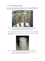
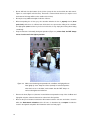
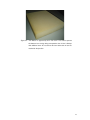
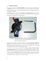
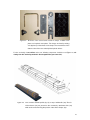
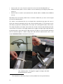
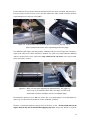
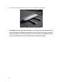
HiSPARC II
Detector Installation
Manual
Version 1.7
Filipe Freire & Bob van Eijk
April 16, 2009
For more information about the HiSPARC project visit:
http://www.hisparc.nl/
This user guide, the HiSPARC II software and other information can be found at:
http://www.hisparc.nl/drupal/
2
Warning:
The HiSPARC detector with its scintillator, light guide and PMT is a fragile device.
Please take the following precautions to avoid damage:
•
Pack the detector carefully during transportation; make sure it will not move inside the
ski box (add additional plastic foam).
•
When tilting the ski box, make sure the high side at which the PMT and cable entry are
located, is always on top. Support the lower end of the scintillator against sliding.
•
When handling the detector outside the ski box, make sure the scintillator and light guide
are supported at the proper positions to avoid breaking the glue connections.
•
Avoid external forces on the PMT and clashes with other objects.
•
Temporarily (paper) tape the cables (and connectors) to the light guide to avoid tension
on the cables (and PMT).
3
4
Contents
1.
Instructions for the installation of HiSPARC detectors
7
2.
Positioning the detectors and GPS antenna
9
3.
On the installation of the ski boxes
11
4.
Placing the ski boxes
14
5.
Available guides, manuals and papers
19
Literature
20
5
6
1.
Instructions for the installation of HiSPARC detectors
The HiSPARC detectors are kept in ski boxes [1] which, used under normal conditions meet the
requirements for application even under extreme weather conditions. The boxes obtain their guaranteed stability by securing them via their standard mounting connections (4 brackets) and properly closing the boxes (hinges and 3-point locking mechanism) and lock (key + lock). To ensure that the boxes
remain secured on the roof even under extreme weather conditions, a robust ‘anchoring’ method has
been developed (Figure 1.1). This anchoring method avoids modifications to the roof itself. Although
the total weight (and therefore the load on the roof) increases, a good spread of the weight ensures
that the load increase remains within limits (less than 50 kg/m2).
Figure 1.1: HiSPARC detector with two ski boxes.
Before the ski boxes with their detectors are placed on the roof several electrical tests have to be completed. The full documentation of the setup has to be made available, both on paper and at the local
(high-school/institute) website. This is the responsibility of the students taking part in the construction
and installation of the detectors. With the help of this documentation the individual measurements from
each scintillator, photo-multiplier tube (PMT) and readout electronics can be combined. This information is essential for the signal analyses and interpretation of the measurements on the cosmic radiation!
7
Before the ski boxes are installed, it is recommended to step through the list below and to
check each item:
•
Each detector has a label with the detector station identification number. This unique number
will also be used in the analysis software and is listed on the status page of the cluster the station belongs to on the HiSPARC website and in the logbook of the detector. This number also
links to the serial number of the PMT.
•
To prevent damage to the PMT during transportation, make sure that the detector arrangement
in the ski box is such that the PMT is always at the higher end of the ski box (same side as
where the cable entry in the bottom of the box is located).
•
Each detector has passed a full electrical test and has been documented (the report is included in the logbook and published at the website of the high-school/institute; a copy is submitted to the coordinating institute).
•
Each detector has been calibrated (documentation: in the logbook, copy at school/institute and
website, and coordinating institute!).
•
1 signal cable (coax) and 1 power cable (5-wires) per ski box have been tested and installed
(the standard - maximum - length of these cables is 30 meters). The cables have number-tags
at both ends. Note that when installing the cables, the power cables are asymmetric; both
ends have a different connector (male/female)! The PMT has a ‘male’ connector and has
to be connected to the female connector of the power cable…
•
The cables in the ‘outside area’ (roof and along the facade) should be preferable assembled in
secure and stable (metal/plastic) cable gutters (the power voltage on the PMTs is 12 Volts and
accepts only limited load). Avoid short circuits; protect the connectors against mechanical
forces, humidity and prevent sharp cable bends!
•
The GPS antenna is mounted on a stable tube or at an antenna anchor in the direct vicinity of
the detector station, so that the antenna has an as large as possible view on the sky. After
proper installation, 5 satellites (at least) or more should be observed simultaneously.
•
The GPS antenna is mounted on a tube/anchor while the antenna has a screw-threat underneath that matches a ¾ ‘’ gas fitting or the supplied plastic antenna stand.
•
The GPS antenna cable has been preferably mounted in a stable cable gutter (also this cable
has a length of 30 meters and should not, without taking special precautions, be modified). The
cable is symmetric; on both ends it has the same connectors, while it should not lay/hang loose,
especially not along a mast (use cable ties)!
•
8
Special precautions should be obeyed with respect to the roof protection against lightning.
2.
Positioning the detectors and GPS antenna
Two different HiSPARC detector configurations are supported; a two-ski box setup (Figure 2.1) and a
four-ski box setup (Figure 2.3). The arrangement with two ski boxes is most suitable when the local
station is combined with other stations in the direct neighbourhood (cluster centres). The total detector
surface area of this station amounts to: 0.5 + 0.5 = 1.0 m2. In order to minimise the angular dependence, the ski boxes are put in parallel (the effective size of the station in two directions will then be 1 m,
Figure 2.1). The ‘typical distance between the two ski boxes should be about 5 to 6 meters.’
Figure 2.1: HiSPARC configuration with two detectors. The total surface of the scintillators
amounts to 1 m2. The GPS antenna can be installed on a stand/plastic anchor
at the middle of the axis connecting the two scintillator centres.
The GPS can be installed at the middle of the axis between the two scintillator centres.
Figure 2.2: The GPS antenna is mounted on the plastic anchor. To prevent
modifications to the roof, the anchor is secured by a weight (tile).
9
The GPS can be positioned at the middle of the axis between the two scintillator centres (Figure 2.2).
Measure the North-South orientation of this axis with a compass and make a sketch.
A configuration with 4 detectors offers the possibility to determine the direction of a local particle
shower. Also here the arrangement has an optimised geometric symmetry; three detectors form the
corner points of an equilateral triangle (with sides of 10 m). The fourth detector is placed at the centre
of gravity of the triangle. When all four detectors generate a signal, 4 triangles can be distinguished, triangulation – for the determination of the shower direction, can be performed 4 times and can be
tested on consistency…
Figure 2.3: HiSPARC configuration with four detectors. The total surface of the scintillators:
2 m2. Detectors 1 and 2 are connected to the Master, while the Slave unit reads
the signals from 3 and 4. The GPS antenna can be mounted on a stand/plastic
anchor precisely half way the axis connecting the scintillator centres of 3 and 4.
The GPS can be installed half way the axis connecting the scintillator centres 3 and 4. If another position is chosen, it is necessary to make a detailed sketch of the position of the GPS antenna with respect to the detectors. Also here, the orientation of the axis between 3 and 4 towards the North has to
be determined with a compass; make a sketch. The number ordering for the detectors should not
be changed (Master: scintillator 1 and 2 and Slave: scintillator 3 and 4)!
10
3.
On the installation of the ski boxes
Please take note of the regulations regarding working on (flat) roofs (i.e. keep a distance of more
than 2 meters from the edge of the roof!). Sometimes these measures can not be met (Figure 3.1).
Figure 3.1: Please pay attention! Working on a roof requires keeping a distance of 2 meters to the edges! Optionally place the GPS on a stable tube or use the plastic
antenna anchor. Do not leave the cable hanging freely off the antenna.
•
Careful! Pay attention when handling the bare detector. The glue connections (scintillator/lightguide and light-guide/PMT) are fragile and may easily break. Unrecoverable damage to the PMT
may be the result.
Figure 3.2: The cable transit is plugged into the hole in the bottom of the ski box in the
vicinity of the PMT The bulk of the transit sits inside the ski box; only the nut at
the bottom of the image above will sit outside the ski box..
11
•
Do not drill holes into (the bottom of) the ski box (except for the one that holds the cable transit,
Figure 3.2, at the higher end of the box). The transit is mounted inside the box (so only the nut at
the bottom of the image will be on the outside of the ski box).
•
Do not place any additional weights inside the ski boxes.
•
When transporting the ski box, pay close attention whether the box is properly closed (three
point lock!), while there is sufficient foam inside the box to prevent the sliding of the scintillator
and light-guide (never leaf the key in the lock of the box, it may simply break away when hitting
something!).
•
Keep the detectors horizontally during transportation (Figure 3.3); when tilted, the PMT always
has to sit at the end in the highest position!
Figure 3.3: Make sure that during transportation the scintillator and light-guide are
fixed tightly by foam. Keep the ski box (locked!) in horizontal position;
when the box has to be tilted, make certain that the PMT always remains at the highest end of the box.
•
Remove the foam (Figure 3.4) that was inserted before transportation on top of the scintillator and
light guide only then, when the detector has arrived at its final position.
•
Measure the precise distance between the GPS antenna and the ski boxes and make a sketch in
which the North-South orientation of the ski boxes is determined by a compass. Include the
sketch in the logbook and publish this information at the local web pages.
12
Figure 3.4: The detector is supported by foam. The foam is also used to prevent
the detector from moving during transportation; the ski box is filled up
with additional foam. Do not remove the foam before the ski box has
reached its final position.
13
4.
Placing the ski boxes
The ski boxes are fixed via their standard attachments. As a result, the stress on the attachments will
be identical to the stress on a car roof-rack. Only in this way, save mounting can be guaranteed.
There are two different series of ski boxes of approximately the same size. However, the way the attachments are secured differs
The first series – older – ski boxes contain 4 clamps and 4 clamp locks (Figure 4.1). Before the
clamps are inserted into the clamp locks from below, it is advised to remove the detector from the ski
box and place it securely on the roof supported by foam.
Figure 4.1: The first series of ski boxes have been delivered with 4 clamps and 4
clamp locks. The clamps are inserted from below into the bottom of
the box and slide into the clamp locks.
The clamp locks are mounted on support rails inside the ski box and are positioned at maximum
distance. The height at which the clamp locks are mounted is flexible but should press the box firmly
to the aluminium profile. The photo shows the clamp lock in ‘unlocked’ position; turn the central part
clockwise and secure the position of the lock with the red cut-out.
The second series –newer – ski boxes are delivered with 4 clamps, 4 rubber cover plates, 4 plastic
cover plates and 8 nuts (Figure 4.2). The clamps are inserted from below into the bottom of the ski
box (chose the holes that are at the largest distance from each other). Next, the rubber cover plate
and plastic cover plate (in this order!) are slid over the clamps. Finally, the bolds are mounted and
press the box firmly to the aluminium profile. The remaining openings in the bottom of the ski box are
covered with black stickers (belong to the contents of the delivery).
14
Figure 4.2: Ski boxes of the second series contain 4 clamps, 4 rubber cover
plates and 4 plastic cover plates. The clamps are fixed by twisting
nuts (8 pieces) on the threats of the clamp. The unused holes in the
bottom of the ski box are sealed by black plastic stickers
For the ‘anchoring’ of one ski box on the roof, following components should be used (Figure 4.3; deviating from this anchoring method is discouraged and at your own risk!):
Figure 4.3: Four concrete sidewalk profiles (01) lay on top of rubber tiles (05). The aluminium beams (02) are pressed to the concrete by attachment links (04)
while at the same time fixing the position of the ski box clamps (03).
15
1
•
8 pieces (100 x 15 x 5 cm) or 4 pieces (100 x 30 x 5 cm) of concrete sidewalk profiles (1).
•
2 aluminium beams (200 x 5 x 2.5 cm stainless steel or aluminium) (2) for fixing the position of the
clamps (3).
•
About 8 meters of stainless steel attachment links (‘Bandit’, width of ¾ inch) and 8 ¾ inch tail
ends (4).
Depending on the roof covering, rubber mats or a number of rubber tiles (5) can be used to support
the concrete sidewalk profiles.1
The stainless steel attachment links (4) are stringed with an attachment grip (upper left corner in
Figure 4.4) around the aluminium beam (2) and concrete sidewalk profiles (1). The beam presses the
two clamps (3) against the sidewalk profiles. The clamps stick out through the bottom of the ski box.
The clamp locks/bolts on the clamps at the inside of the ski box ensure the tight mounting of the box
onto the beam. The stainless steel toggle (bottom left) has joggles and ridges (upper right) with which
the attachment link is kept under tension. With a hammer, the ridges are ‘bent’ around the attachment
link. The attachment grip has a build-in cutting device with which the attachment link can be cut to
length. 8 attachment links are mounted for each ski box.
Figure 4.4: The attachment links are stringed around the aluminium beam and concrete sidewalk profiles. The toggle has joggles and ridges with which
the attachment link is secured.
1
16
This material has to be purchased by the school (available from 'do it yourself markets’).
Put the detector back into the box when the attachment links have been assembled. Note that the cable trays need to reach the ski box as far as possible and that the cables should exceed the minimum
required length to the connectors of the PMTs.
Figure 4.5: Another detail of the attachment link and attachment grip (left). The detector is put back into the box and is supported by plastic foam (right).
The additional cable length is kept alongside the scintillator inside the ski box (Figure 4.6). Herewith, a
simple strain relief for the cables and PMT is obtained. The cables are provided with two additional
cable ties mounted close to the cable transit (they should not be cut short!). In this way an additional strain relief is created.
Figure 4.6: Make sure that when tightening the attachment links, the joggles remain on top of the aluminium beam (left). The ridges can then easily
be bent with a hammer. Installation has almost completed (right).
Each detection station possesses two sets of keys. One set is guarded by the school (blue label); the
spare keys are collected and stored by the cluster coordinator (red label).
Finally, it is extremely important to properly close the lid of the ski box - the lid should match at all
edges, while the key can be turned without applying any force - (Figure 4.7). Ofcourse, no plastic
17
foam should be left inside the ski box on top of either the scintillator or the light guide.
Figure 4.7: Ready to measure cosmic particles!
DISCLAIMER: The anchoring method described in this document has been developed on the
basis of information provided by the manufacturer of the ski boxes and has been verified by
mechanical engineers. The method has proven itself over the past years. Modification in any
way of this method will be your own responsibility and is strongly discouraged!
18
5.
Available guides, manuals and papers
Following HiSPARC user guides and installation manuals are available in pdf format (Dutch and English language) and can be found at the HiSPARC website:
http://www.hisparc.nl/
•
Detector Construction Manual (Version 1.0).
•
Software Installation Manual (Version 1.0).
•
Detector Installation Manual (Version 1.7).
•
Data Acquisition User Guide (Version 2.2).
•
Data Analysis User Guide (Version 1.0).
In addition, a number of articles on selected topics (Dutch language only!)
•
Poisson Statistiek.
and educational material is also available:
•
Koos Kortland
•
Anneke de Leeuw
•
Kosmische Straling.
19
Literature
[1]
Ski box ‘Jetbag Apollo 700’ (2325 x 690 x 400) see for instance:
http://www.hapro.nl/, http://www.jetbag.com/
20