1
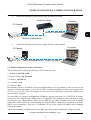
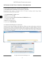
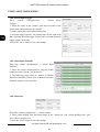
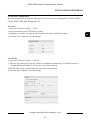
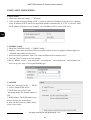
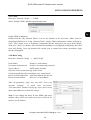
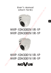
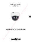
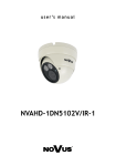
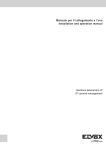
U s e r ’s m a n u a l
NVIP-3000 series IP camera
NVIP-3000 series IP camera user’s manual
IMPORTANT SAFEGUARDS AND WARNINGS
EMC (2004/108/EC) and LVD (2006/95/EC ) Directives
CE Marking
Our products are manufactured to comply with requirements of following directives and
national regulations implementing the directives:
•
Electromagnetic compatibility EMC 2004/108/EC.
•
Low voltage LVD 2006/95/EC with further amendment. The Directive applies to electrical
equipment designed for use with a voltage rating of between 50VAC and 1000VAC as well
as 75VDC and 1500VDC.
WEEE Directive 2002/96/EC
Information on Disposal for Users of Waste Electrical and Electronic Equipment
This appliance is marked according to the European Directive on Waste Electrical and
Electronic Equipment (2002/96/EC) and further amendments. By ensuring this product is
disposed of correctly, you will help to prevent potential negative consequences for the
environment and human health, which could otherwise be caused by inappropriate waste handling of
this product.
The symbol on the product, or the documents accompanying the product, indicates that this
appliance may not be treated as household waste. It shall be handed over to the applicable collection
point for the waste electrical and electronic equipment for recycling purpose. For more information
about recycling of this product, please contact your local authorities, your household waste disposal
service or the shop where you purchased the product.
RoHS Directive 2002/95/EC
Concerning for human health protection and friendly environment, we assure that our
products falling under RoHS Directive regulations, regarding the restriction of the use of
hazardous substances in electrical and electronic equipment, were designed and
manufactured in compliance with mentioned regulation. Simultaneously, we claim that our
products were tested and do not contain hazardous substances exceeding limits which could have
negative impact on human health or natural environment.
Information
The device, as a part of professional CCTV system used for surveillance and control, is not designed for
self installation in households by individuals without technical knowledge.
The manufacturer is not responsible for defects and damages resulted from improper or inconsistent
with user’s manual installation of the device in the system.
ATTENTION!
PRIOR TO UNDERTAKING ANY ACTION THAT IS NOT PROVISIONED FOR THE GIVEN PRODUCT IN ITS
USER’S MANUAL AND OTHER DOCUMENTS DELIVERED WITH THE PRODUCT, OR THAT ARISES FROM
THE NORMAL APPLICATION OF THE PRODUCT, ITS MANUFACTURER MUST BE CONTACTED OR THE
RESPONSIBILITY OF THE MANUFACTURER FOR THE RESULTS OF SUCH AN ACTION SHELL BE
EXCLUDED.
All rights reserved © AAT Holding sp. z o.o.
2
NVIP-3000 series IP camera user’s manual
IMPORTANT SAFEGUARDS AND WARNINGS
WARNING!
THE KNOWLEDGE OF THIS MANUAL IS AN INDESPENSIBLE CONDITION OF A PROPER DEVICE
OPERATION. YOU ARE KINDLY REQUSTED TO FAMILIRIZE YOURSELF WITH THE MANUAL PRIOR TO
INSTALLATION AND FURTHER DEVICE OPERATION.
WARNING!
USER IS NOT ALLOWED TO DISASSEMBLE THE CASING AS THERE ARE NO USER-SERVICEABLE
PARTS INSIDE THIS UNIT. ONLY AUTHORIZED SERVICE PERSONNEL MAY OPEN THE UNIT
INSTALLATION AND SERVICING SHOULD ONLY BE DONE BY QUALIFIED SERVICE PERSONNEL AND
SHOULD CONFORM TO ALL LOCAL REGULATIONS
1. Prior to undertaking any action please consult the following manual and read all the safety and
operating instructions before starting the device.
2. Please keep this manual for the lifespan of the device in case referring to the contents of this
manual is necessary;
3. All the safety precautions referred to in this manual should be strictly followed, as they have a
direct influence on user’s safety and durability and reliability of the device;
4. All actions conducted by the servicemen and users must be accomplished in accordance with the
user’s manual;
5. The device should be disconnected from power sources during maintenance procedures;
6. Usage of additional devices and components neither provided nor recommended by the producer
is forbidden;
7. You are not allowed to use the camera in high humidity environment (i.e. close to swimming pools,
bath tubs, damp basements);
8. Mounting the device in places where proper ventilation cannot be provided (e. g. closed lockers
etc.) is not recommended since it may lead to heat build-up and damaging the device itself
as a consequence;
9. Mounting the camera on unstable surface or using not recommended mounts is forbidden.
Improperly mounted camera may cause a fatal accident or may be seriously damaged itself. The
camera must be mounted by qualified personnel with proper authorization, in accordance with this
user’s manual.
10. Device should be supplied only from a power sources whose parameters are in accordance with
those specified by the producer in the camera technical datasheet. Therefore, it is forbidden to
supply the camera from a power sources with unknown parameters, unstable or not meeting
producer’s requirements;
Due to the product being constantly enhanced and optimized, certain parameters and functions
described in the manual in question may change without further notice.
We strongly suggest visiting the www.novuscctv.com website in order to access the newest manual .
Technical changes reserved without prior notice and printing errors possible.
All rights reserved © AAT Holding sp. z o.o.
3
NVIP-3000 series IP camera user’s manual
TABLE OF CONTENTS
TABLE OF CONTENTS ..................................................................................................... 4
1. START-UP AND INITIAL IP CAMERA CONFIGURATION ................................. 6
1.1. Overview ............................................................................................................. 6
1.2. Starting the IP camera.......................................................................................... 6
1.3. Initial configuration via the web browser ............................................................ 7
2. NETWORK CONNECTION UTILIZING WEB BROSWER .................................. 8
2.1. Recommended PC specification for web browser ............................................... 8
2.2. Connection with IP camera via web browser ....................................................... 8
3. USING AND CONFIGURING ..................................................................................... 10
3.1. Remote Preview Interface. ................................................................................. 10
3.2. Video Record and Playback. .............................................................................. 11
3.3. Right-click Function. .......................................................................................... 11
3.4. Snap Pictures. ..................................................................................................... 12
3.5 System Configuration .......................................................................................... 13
3.5.1 Basic Information ....................................................................................... 13
3.5.2 Date & Time............................................................................................... 13
3.5.3 SD Card ...................................................................................................... 14
3.6 Video Configuration ............................................................................................. 15
3.6.1 Camera Configuration ................................................................................ 15
3.6.2 Video Stream.............................................................................................. 16
3.6.3 Time Stamp ................................................................................................ 16
3.6.4 Video Mask ................................................................................................ 17
3.7. PTZ Config ......................................................................................................... 17
3.8. Alarm Configuration .......................................................................................... 18
3.8.1 Motion Detection Area............................................................................... 18
3.8.2 Motion Detection Trigger .......................................................................... 18
3.8.3 Motion Detection Schedule ........................................................................ 19
3.8.4 Alarm Input Trigger ................................................................................... 20
3.8.5 Alarm Input Schedule ................................................................................ 20
3.8.6 Alarm out ................................................................................................... 20
3.9 Network Configuration ........................................................................................ 21
3.9.1 Port ............................................................................................................. 21
3.9.2 Wired .......................................................................................................... 21
All rights reserved © AAT Holding sp. z o.o.
4
NVIP-3000 series IP camera user’s manual
TABLE OF CONTENTS
3.9.4 IP Notify .................................................................................................... 22
3.9.5 DDNS Config............................................................................................. 22
3.9.6 RTSP .......................................................................................................... 22
3.9.7 UPNP ......................................................................................................... 23
3.9.8 Mail Config................................................................................................ 23
3.9.9 FTP ........................................................................................................... 24
3.10 Advanced Config ............................................................................................... 24
3.10.1 User Config.............................................................................................. 24
3.10.2 Security Configuration ............................................................................ 26
3.10.3 Config Backup & Restore ........................................................................ 26
3.10.4 Reboot ...................................................................................................... 27
3.10.5 Upgrade .................................................................................................... 27
4. MOBILE SURVEILLANCE ...................................................................................... 28
4.1. Mobile Surveillance via iPhone. ........................................................................ 28
4.1.1 Install Mobile Surveillance software directly via iPhone .......................... 28
4.1.2 Install Mobile Surveillance software via PC ............................................ 29
4.1.3 SuperLivePro Instruction ........................................................................... 31
4.2. Mobile Surveillance via Android OS smartphone ............................................. 37
4.2.1 Software Installation .................................................................................. 37
5. RESTORING FACTORY DEFAULTS .................................................................... 42
All rights reserved © AAT Holding sp. z o.o.
5
NVIP-3000 series IP camera user’s manual
START-UP AND INITIAL CAMERA CONFIGURATION
1. START-UP AND INITIAL IP CAMERA CONFIGURATION
1.1. Overview
Following manual for IP Cameras NVIP-7000 series contains detailed information about camera
connection and operation, main page introduction, system related settings and camera settings.
Note
In this document you can find all available functionality. Depending on camera model some features
might be unavailable.
1.2. Starting the IP camera
To run NOVUS IP camera you have to connect ethernet cable between camera and network switch.
To power it up you can connect it directly via power supply adapter with parameters compatible with
camera power supply specification, or camera can be powered with PoE/PoE+ (IEEE 802.3af/802.3at)
compatible switch.
After connecting power supply green LED should light on. Initialization process is then started which
takes about 30 seconds. You can then proceed to connect to the camera via web browser.
If the connection is successfully established orange LED blinks with a frequency proportional to the
quantity of data sent. Connecting via web browser is then possible. If connection isn’t established (the
network cable is disconnected) green and orange LEDs aren't active, solid light means that network
connection is ok but camera doesn't receive or send any data, with possible PC network settings error.
The recommended way to start an IP camera and perform its configuration is a connection directly
to the network switch which is not connected to other devices. To obtain further information about
network configuration parameters (IP address, gateway, network mask, etc.) please contact your
network administrator.
•
Connection utilising network switch with PoE/PoE+ support
Network Switch PoE/PoE+
Computer
IP Camera
Network transmission
Power supply and
All rights reserved © AAT Holding sp. z o.o.
6
NVIP-3000 series IP camera user’s manual
START-UP AND INITIAL CAMERA CONFIGURATION
•
Connection utilising external power supply and network switch
Network Switch
Computer
IP Camera
Network transmission
Network transmission
•
Connection utilising external power supply directly to the computer
Computer
IP Camera
Network transmission - cross over cable
1.3. Initial configuration via the web browser
The default network settings for IP camera NVIP-7000 series are:
1. IP address= 192.168.1.200
2. Network mask - 255.255.255.0
3. Gateway - 192.168.1.1
4. User name - root
5. Password - pass
Knowing the camera’s IP address you need to appropriately set PC IP address, so the two devices can
operate in one network subnet ( e.g. for IP 192.168.1.1, appropriate address for the camera ranges from
192.168.1.2 to 192.168.1.254, for example 192.168.1.60). It is not allowed to set the same addresses for
camera and PC computer
You can either set a network configuration (IP address, gateway, net mask, etc.) of NOVUS IP camera
yourself or select DHCP mode (DHCP server is required in this method in target network) by using
web browser or by NMS software. When you use DHCP server check IP address lease and its linking
with camera MAC address to avoid changing or losing IP address during device operation or network/
DHCP server breakdown. You have to remember to use a new camera IP address after changing
network parameters.
After network setting configuration has been done, the camera can be connected to a target network.
All rights reserved © AAT Holding sp. z o.o.
7
NVIP-3000 series IP camera user’s manual
NETWORK CONNECTION UTILIZING WEB BROWSER
2. NETWORK CONNECTION UTILIZING WEB BROSWER
2.1. Recommended PC specification for web browser connections
Requirements below apply to connection with an IP camera, assuming smooth image display
in 1920x1080 resolution and 25 fps speed.
1. CPU Intel Pentium IV 3 GHz or newer
2. RAM Memory min. 512 MB
3. VGA card (any displaying Direct 3D with min. 128 MB RAM memory)
4. OS Windows XP / VISTA
5. Direct X version 9.0 or newer
6. Network card 10/100/1000 Mb/s
2.2. Connection with IP camera via web browser
You have to enter camera IP address in the address bar. When you connect to the camera, web browser
will download the applet for displaying images from the camera. In Internet Explorer it may be
necessary to accept an ActiveX control. To do this, click the right mouse button on the message, select
"Install Active X control" and then click Install. After successfully SuperClient2 plug in downloading
run and install it on a computer.
All rights reserved © AAT Holding sp. z o.o.
8
NVIP-3000 series IP camera user’s manual
NETWORK CONNECTION UTILIZING WEB BROWSER
If the installation fails, changing security settings for the IE browser is required. In order to do that,
please choose: Tools > Internet options > Security tab > Custom level and:
•
Under Download unsigned ActiveX controls - select either Enable or Prompt
•
Under Initialize and script ActiveX controls not marked as safe - select Enable or Prompt
You can also add the camera’s IP address to “trusted zone” and set lowest security level for it.
In addition, when working in Windows Vista/7 the ActiveX applet may be blocked by Windows
Defender or User account control. In such case you should allow to run this applet, or simply disable
these functions.
After successful installation login window will be displayed. Default user is root and default password
is pass. For safety reasons, it is recommended to change default user name and password.
All rights reserved © AAT Holding sp. z o.o.
9
NVIP-3000 series IP camera user’s manual
USING AND CONFIGURING
3. USING AND CONFIGURING
3.1 The Remote Preview Interface
5
1
2
3
4
1. Motion detection
Motion detection icon changes color from white to red when motion is detected.
Alarm icon changes color from white to red when alarm situation has occured.
2. Display fluency settings
It is possible to increase video display fluency by setting video buffor (0 ~ 4 seconds).
3. Video size settings
Fix size
Zoom in
Zoom in
Zoom out
4. Local record
Start record
Snap
Playback
Enable / disable audio
5. PTZ - Function unavailable
All rights reserved © AAT Holding sp. z o.o.
10
Full screen
NVIP-3000 series IP camera user’s manual
USING AND CONFIGURING
3.2 Video Record and Playback
To start recording click
icon and specify file path.
After selecting the record date, the record files will be displayed in the record file list box. Double
click a certain record file to playback or check a certain file. Then click Play button to do playback. It
is possible to do relating operation according to some buttons in the playback interface.
Playback
Fast Forward
Zoom In
Pause
Next Frame
Oddal
Stop
Previous File
Full Screen
Next File
Path
3.3 Right-click Function
Clicking right mouse will appear a pull-down list as below:
1 Stream:
Current resolution for first stream.
2 Stream:
Current resolution for second stream.
Turn off the live:
Click this item to close present live preview.
Enable audio:
Enable remote audio transmission. Users can
hear the audio from the IP Camera.
Full screen:
The live preview picture will full-screen
display. Double click or click right mouse to return to the previous interface.
Online user:
Display user’s list connect to the device.
System information: Display the device information: device name, firmware version, software
build date, kernel version and hardware version.
All rights reserved © AAT Holding sp. z o.o.
11
NVIP-3000 series IP camera user’s manual
USING AND CONFIGURING
3.4 Snap Pictures
To take a picture click “Snap”
icon.
User can snap multiple pictures. Select the picture number from Frame pull down list box and check
“Title” and “Time” to show capture title and time on the snap pictures simultaneously.
Click “Browse” to set saving path. Click “Save” to save pictures to HDD on the computer. Click
“Printer setup” to set the printer and print the snap pictures. Drag the scroll bar to view all snapped
pictures.
All rights reserved © AAT Holding sp. z o.o.
12
NVIP-3000 series IP camera user’s manual
USING AND CONFIGURING
3.5 System Configuration
The “System configuration” includes two submenus: Basic Information and Date & Time.
3.5.1 Basic Information
In the “Basic Information” interface, user can setup the device name and also can check the relative
information of the server.
To change device name:
1. Click the "Config" icon to show menu list.
2. Enter into “System Config” -> “Basic Information "
3. Input the name of the device in the "Device name" text box.
4. Press the "Save" button to save the settings.
3.5.2 Date & Time
To change date and time:
1. Enter into "System Config" -> “Date & Time”
2. Choose the right "Time Zone" according to user’s location.
3. User can also enable DST and set DST mode and time.
4. Selecting “Manual", user can self-define time
4. It is possible to synchronize time with NTP Server.
5. Press the "Save" button to save the settings.
All rights reserved © AAT Holding sp. z o.o.
13
NVIP-3000 series IP camera user’s manual
USING AND CONFIGURING
3.5.3 SD card
Enter into "System Config" -> “SD Card”.
1. Click “Format SD card” to format micro SD card.
2. Click "Eject card" to stop writing data to micro SD card. Then the micro SD card can be ejected
safely.
Note: Using SD card function should be coordinated with motion alarm. When alarm is triggered,
the system will automatically snap picture and save the picture into micro SD card.
All rights reserved © AAT Holding sp. z o.o.
14
NVIP-3000 series IP camera user’s manual
USING AND CONFIGURING
3.6 Video Configuration
3.6.1 Camera Configuration
1. Enter into "Video Config" -> "Camera".
2. User can adjust Brightness, Contrast, Hue and saturation of the picture.
3. It is possible to select white balance mode.
4. Sharpen, denoise, white balance, frequency and distortion correction are adjustable.
5. User also can enable the image mirror and image overturn function.
6. Day-night mode allows to choose: LightAutomatic (user can set the day and night mode
switching threshold), Daytime, Night and Timing (set the hour to switch mode).
7. Night Mode Advanced Settings allows to set denoise and image gain functions.
8. Press the "Save" button to save the settings.
All rights reserved © AAT Holding sp. z o.o.
15
NVIP-3000 series IP camera user’s manual
USING AND CONFIGURING
3.6.2 Video Stream
1.Enter into "Video Config" -> "Video Stream".
2. Select the resolution, frame rate, bitrate type, video quality and bitrate at the pull down list.
3. User can also set I Frame Interval (25~100 range) and profile (Base Line or Main Profile).
4. Select the data stream type at the "Bitrate type" pull down list.
5. Set audio encoding and audio in type.
6. Choose the alarm picture size.
7. “Video encode slice split” increase cameras efficiency, but with this function on, camera may do
not be compatible with all previous devices.
8. Press the "Save" button to save the settings.
3.6.3 Time Stamp
Enter into "Video Config" -> "Time Stamp" to change OSD options.
User can display date, device name and custom OSD.
To change text location, drag displayed text with left mouse button.
To save changes press “Save” button.
All rights reserved © AAT Holding sp. z o.o.
16
NVIP-3000 series IP camera user’s manual
USING AND CONFIGURING
3.6.4 Video Mask
User can set up to 4 video masks.
To add video mask press “Draw” button and mark mask on video preview. Chosen area will cover
with green grid. To activate mask check “Enable Video Mask”. To save settings press “Save” button.
Press “Clear” button to remove all video masks.
3.7 ROI Config
Function unavailable.
3.7 PTZ Config
Function unavailable.
All rights reserved © AAT Holding sp. z o.o.
17
NVIP-3000 series IP camera user’s manual
USING AND CONFIGURING
3.8 Alarm Configuration
3.8.1 Motion Detection Area
1. Enter into “Alarm configuration" -> "Motion Detection Area" to see a interface.
2. Move the "Sensitivity" scroll bar to setup the motion trace sensitivity.
3. Check the "Add”, press the "Ctrl" button and move mouse to select the motion detection area.
Select “Erase” and move the mouse to clear all motion detection area.
4. Press the "Save" button to save the settings.
3.8.2 Motion Detection Trigger
1. Enter into “Alarm Configuration" -> "Motion Detection
Trigger"
2. Check "Enable alarm" check box. Then all functions
under this interface will be activated.
4. Trigger Email: Check “Attach picture” and select email
addresses in the “Receival email address” text box (Email
address shall be set first in the Mail config interface). Then
the triggered snap pictures will be sent into those address.
User also can define the subject and content of the email.
5. Trigger FTP: Check “Uploading picture”. Then the
triggered snap pictures will be sent into FTP server address.
Please refer to FTP configuration chapter for more details.
6. Press the "Save" button to save the settings.
All rights reserved © AAT Holding sp. z o.o.
18
NVIP-3000 series IP camera user’s manual
USING AND CONFIGURING
3.8.3 Motion Detection Schedule
Enter into “Alarm Config" -> "Motion Detection schedule"
Week schedule
User can set alarm time for every weekday separately in one week.
Note: It is possible to choose hours from 0-24 range. Mouse clicks on the panel to set the alarm
hours. Green means selected area, blank means unselected area.
"Add": add the schedule for a special day.
"Erase": delete holiday schedule
Day schedule
User could set alarm time for alarm in some time of special day, such as holiday.
1. Select a date at the "Date" pull down list, press "Add" button to add that date to the list box on the
right side and then move the scroll bar to set the schedule of that day.
2. Select a date in the list box on the right side, and press "Erase" to remove the schedule on that
day.
Press the "Save" button to save the settings.
Note: Holiday schedule is prior to Week schedule.
All rights reserved © AAT Holding sp. z o.o.
19
NVIP-3000 series IP camera user’s manual
USING AND CONFIGURING
3.8.4 Alarm Input Trigger
Enter “Alarm Configuration" -> "Alarm Input
Trigger".
1. Select the sensor at the "Sensor" pull down list and set the
sensor name and alarm type: NO and NC.
2. Enable alarm and select alarm holding time.
3. Set alarm trigger options. The setting steps are the same with
that of motion detection trigger. Please refer to motion detection
trigger chapter for details.
4. Press the “Save” button to save the settings.
3.8.5 Alarm Input Schedule
Enter into “Alarm Configuration" -> “Alarm Input
Schedule”.
1. Select the sensor which needs to setup the alarm
parameter at the "Sensor" pull down list
2. The following setup steps are similar to Motion
Detection Schedules. Please refer to Motion Detection
Schedule chapter for more details.
3.8.6 Alarm out
Enter into “Alarm configuration" -> "Alarm output".
1. Select alarm holding time and alarm name at the "Alarm out” and “Alarm holding time” pull
down list box respectively.
2. Press the "Save" button to save the settings
All rights reserved © AAT Holding sp. z o.o.
20
NVIP-3000 series IP camera user’s manual
USING AND CONFIGURING
3.9 Network Configuration
Network configuration includes ten submenus: Port, Wired, Server Configuration, IP Notify, DDNS
Config, RTSP, UPNP, Mail Setting and FTP.
3.9.1 Port
1. Enter into "Network Config" -> "Port"
2. Input port number in the "HTTP Port" textbox.
3. Input the port number for audio & video transmission in the "Data Port" textbox.
4. Press the "Save" button to save the settings.
3.9.2 Wired
1. Enter into "Network Config" -> "Wired"
2. There are two Options for setup IP: “Obtain an IP address automatically” by DHCP protocol or
“Use the following IP address”, where user can set data manually.
5. PPPOE: User needs to manual input the user name and password.
4. Press the "Save" button to save the settings.
All rights reserved © AAT Holding sp. z o.o.
21
NVIP-3000 series IP camera user’s manual
USING AND CONFIGURING
3.9.4 IP Notify
1. Enter into “Network Config” -> ”IP Notify”
2. If the “Enable notifying change of IP” is selected, when the IP address of the device is changed,
a new IP address will be sent to the appointed mailbox automatically. If “FTP” is selected, when
the IP address of the device was changed, a new IP address will be sent to FTP server.
3.9.5 DDNS Config
1. Enter into "Network Config" -> "DDNS Config"
2. Register a user name and a password to log on the website of service supplier, and then apply for
a domain name online for the server.
3. After sucessful registration, input User Name and Password for chosen server.
4. Press the "Save" button to save the settings.
Allowed DDNS servers: www.dns2p.net, www.88ip.net, www.meibu.com, www.dyndns.com,
www.no-ip.com, www.3322.org and mintdns type.
3.9.6 RTSP
Enter into “Network Config” -> “RTSP”
1. Select “Enable RTSP server”.
2. RTSP Port: Access Port of the
streaming media. The default number is
554.
3.RTSP Address: The RTSP address you
need to input in the media player.
4. You can also choose to enable anonymous viewer login.
All rights reserved © AAT Holding sp. z o.o.
22
NVIP-3000 series IP camera user’s manual
USING AND CONFIGURING
3.9.7 UPNP
Enter into “Network Config” -> “UPNP”
Select “Enable UPNP” and then input friendly name.
Enable UPNP in Windows
Double-click the “My Network Places” icon on the desktop in PC and select “Show icons for
networked UPnP devices” in the “Network Tasks” list box. Then a information window will pop up.
Click “YES” button to see a “Windows Components Wizard” dialog box pop up as shown below.
Then press “Next” to continue. After finished the installation of configuring components, the UPnP
icons will display. Users can double-click certain icon to connect the remote surveillance login
interface through IE.
3.9.8 Mail Config
Enter into “Network Config” -> “Mail Config”
From Email:
Sender’s e-mail address
User name and password: Sender’s user name and password
Server address:
SMTP name of sender
Select the secure connection type at the Secure
Connection pull down list according to user’ actual needs
Receival email address list: Add email address into the list
Receival email address:
Receiver’s e-mail address
After all parameters setup, user can click “Test your
account settings”. If email sent successful,
“Test Successful” window will pop up, if not, users can try
other email addresses or check the setting.
Note: If user change the static IP into PPPoE and select
mailbox, there will be an e-mail sent to user’s mail box for
notify a new IP address.
All rights reserved © AAT Holding sp. z o.o.
23
NVIP-3000 series IP camera user’s manual
USING AND CONFIGURING
3.9.9 FTP
Enter into “Network Config” -> “FTP Setting”
Add:
Click Add button to input FTP server’s server name,
address, port number, user name, password, and
upload path, click OK to confirm the setting.
Modify: User can click this button to change some
information of the FTP server
Delete:
Select certain FTP account; Click this button to
delete this account
Test :
Select certain FTP account; Click this button to test
its valid or not.
3.10 Advanced Config
Advanced configuration includes five submenus: User Configuration, Onvif Configuration, Security
Configuration, Configure Backup & Restore, Reboot and Upgrade.
3.10.1 User Config
Enter into “Advanced Config” -> "User Config"
All rights reserved © AAT Holding sp. z o.o.
24
NVIP-3000 series IP camera user’s manual
USING AND CONFIGURING
Add user:
1. Click "Add" button. “Add User” dialog box will pop up.
Note: After bind physical address to the IP Camera, user can access
the device on this PC in network only. If the MAC address was
“00:00:00:00:00:00” it can be connected to any computer.
2. Input user name in "User Name" textbox (only letters).
3. Input characters in "Password" and "Confirm Password" textbox
(letters or numbers).
4. Input the MAC address of the PC in "Binding MAC address"
textbox.
5. Click “OK” button and then the new added user will display in
the user list.
Modify user:
1. Select the user to modify password and physical address in the user configuration list box.
2. Click “Modify” button. “Modify user” dialog box will pop up.
3. Input original password of this user in the “password” text box.
4. Input new password in the “New password” and “Confirm” text box.
5. Input computer’s physical address in the “User PC MAC” text box.
6. Click “OK” button to modify user’s password and bind MAC address successfully.
Delete user:
1. Select the user which needs to be deleted in the user configuration list box.
2. Click “Delete” button will pop up a confirm dialog box. Click “OK” to delete the user.
Note: The default super administrator cannot be deleted.
All rights reserved © AAT Holding sp. z o.o.
25
NVIP-3000 series IP camera user’s manual
USING AND CONFIGURING
3.10.2 Security Configuration
Enter into “Advanced Config” -> "Security Config”
IP address filter setting
Check “Enable IP address” check box, select “Deny
the following IP address”, input IP address in the IP
address list box and click “Add” button. Then this
IP address will display in the list box. Option
“Allow the following IP address” is the same with
“Deny the following IP address”.
Select the IP address which needs to be deleted
from the IP address list box and click “Delete” button to delete that IP address.
Click "Save" button to save the above setting.
MAC filter setting
Check “Enable MAC address” check box, select “Deny the following IP address”, input MAC address in the MAC address list box and click “Add” button. Then this MAC address will display in
the list box. Option “Allow the following MAC address” is the same with “Deny the following IP
address”.
Select the MAC address which needs to be deleted from the MAC address list box and click
“Delete” button to delete that MAC address.
Click "Save" button to save the above setting.
3.10.3 Config Backup & Restore
Enter into “Advanced Config” -> "Config Backup & Restore”
Import & Export Configuration:
User can import or export the setting information from PC or to device.
To Import Setting: Click “Browse” to select save path to import information from PC. User can
import all setting information to PC, but “user configuration” and “network configuration” are
exceptional. To start import click “Import setting”.
To Export Setting: Click “Export setting”
Default setting
Click “Load default” button to restore all system settings to default status.
All rights reserved © AAT Holding sp. z o.o.
26
NVIP-3000 series IP camera user’s manual
USING AND CONFIGURING
3.10.4 Reboot
Enter into “Advanced Config” -> “Reboot”.
Click “Reboot” button to reboot the device.
3.10.5 Upgrade
Enter into “Advanced Config” -> “Upgrade”
1. Click “Browse” button to select the upgrade file
2. Click “Upgrade server firmware” button to start upgrading the application program
3. The device will restart automatically
4. After you successfully update the software, click “OK” button to close IE and then re-open IE to
connect IP Camera.
Notice: During upgrade user can’t disconnect IP camera from PC or turn off IP camera.
All rights reserved © AAT Holding sp. z o.o.
27
NVIP-3000 series IP camera user’s manual
MOBILE SURVEILLANCE
4. MOBILE SURVEILLANCE
This IP-CAM supports mobile surveillance by phones with Windows mobile, iPhone, Android and
Blackberry OS. Please check the operation system version of mobile before use; and connect the
IP-CAM to Internet.
4.1. Moblie Surveillance via iPhone
4.1.1 Install Mobile Surveillancec software directly via iPhone.
1. Open App Store software.
2. Search “SuperLive Pro” and click “Free” button.
3. Click “Install App” button.
4. Input iTunes Store password and then click “OK”. The software will be installed automatically.
All rights reserved © AAT Holding sp. z o.o.
28
NVIP-3000 series IP camera user’s manual
MOBILE SURVEILLANCE
4.1.2 Install Mobile Surveillance software via PC.
1. Install iTunes store on PC and login.
2. Connect iPhone with PC.
3. Search “SuperLivePro” and select it.
All rights reserved © AAT Holding sp. z o.o.
29
NVIP-3000 series IP camera user’s manual
MOBILE SURVEILLANCE
4. Click “Download” button.
5. Input username and password.
6. Install SuperLivePro software to iPhone/iPad.
All rights reserved © AAT Holding sp. z o.o.
30
NVIP-3000 series IP camera user’s manual
MOBILE SURVEILLANCE
4.1.3 SuperLivePro Instruction
Login
1. Choose network type. There are two network connection ways:
•
3G/3G +WIFI, well video quality. This network supports main stream and sub stream. The
real-time image will be displayed by using sub stream.
•
3G-, poor video quality compared with network mentioned above.
2. Input server, account and password.
Server: WAN IP address (or domain name) plus HTTP port of the device. For example: 210.21.183:89
or 123.dvrdydns.com:89.
Note: The default http port of the device is 80. If this port is modified, please use the modified port.
Account and Password: The login account and password of the device. The default account is root and
the default password is pass.
3. Click【Login】button to access the device.
Main Interface
All rights reserved © AAT Holding sp. z o.o.
31
NVIP-3000 series IP camera user’s manual
MOBILE SURVEILLANCE
There are many buttons in the main interface, such as, screen mode, favorite channel, snap, record,
open/close audio, talk, PTZ., etc.
:Image view button. The pictures snapped in the live will be checked by clicking this button.
:Playback button. Click this button to enter into playback interface.
:Settings button. Click this button to set local configuration (Some can also support remote
configuration).
:Information button. Click this button to check lots of information including local
information, device information, network information, etc.
:Server list button. Click this button to add server list.
:Help button.
:CMS button. Preview the live image of multi-devices.
:Log off button. Click this button to return to the login interface.
:Screen mode button. You can choose 1,4,6,8,9,13 or 16 screen
display mode.
:Favorite channel display button. If you save your favorite channel in the favorite server list,
clicking this button will directly play all favorite channels you have saved.
:Snap button. Choose the channel and click this button to capture the channel image.
:Local record button. Choose the channel and click this button to start recording.
: Open/Close audio. Choose the channel and click this button to open/close the audio of this
channel.
:Open/Close talk. Click this button to pop up the servers which support talk function. Select
the device to start talking.
:Set video parameter button. Select the channel and click this button to set the video
parameters including brightness, hue, saturation and contrast.
:PTZ button. Click this button to pop up PTZ control panel.
:Choose bitrate priority or quality priority according to your network
condition.
All rights reserved © AAT Holding sp. z o.o.
32
NVIP-3000 series IP camera user’s manual
MOBILE SURVEILLANCE
Channel indicator instruction:
:Video loss
:Sensor alarm
: Schedule recording
:Others
:Motion alarm
:Motion /sensor alarm based recording or manual recording
Server list
Click
button to show adding new devices window.
Add device: Click “Add” button in the top right corner to pop up a dialog box as shown in the
following left picture. Input the relative information of device and click “Save” button.
Delete device: Click
button behind the device name to delete this device.
Edit device: Click
button behind the device name to edit the information of this device.
Backup & restore: It is recommended to click “Backup” button to reserve the information of all
devices. Then you can click “Restore” button to restore all device information
after you re-install the client or accidently delete the device.
Connection symbols:
indicates the device has been connected.
indicates the device is connecting.
indicates the device is not connected.
All rights reserved © AAT Holding sp. z o.o.
33
NVIP-3000 series IP camera user’s manual
MOBILE SURVEILLANCE
Live Preview
Once you access the device, the system will automatically display the screen mode in accordance
with the channel number of the device.
Note: The maximum number of channels which can be connected is nine.
1.
Click “Screen mode” button to select channel as shown in Fig 1.
2.
When there is video playing in a screen, you can switch the channel by long pressing the
screen as shown in Fig 2.
3.
When no video is playing in a screen, click this screen to choose channel as shown in Fig 3.
4.
When the single channel is playing, you can zoom in/out the image by swiping you finger up
and down as shown in Fig 4.
5.
When the single channel is playing, the channel can be switched by swiping your finger left or
right as shown in Fig 5.
6.
When multi channels are playing, drag one channel screen to the other channel screen. This
will make these two channels change the position of each other.
Fig 1
Fig 2
Fig 3
Fig 4
Fig 5
All rights reserved © AAT Holding sp. z o.o.
34
NVIP-3000 series IP camera user’s manual
MOBILE SURVEILLANCE
CMS Function
This function makes multi-device management.
1. Click
to enable CMS function. When this icon turns green, it means this function is enabled.
2. Click
to choose channel as shown in the right picture. After you choose the channel, click
“ok”, the system will display the related image automatically.
If channels have been added into the group, you can see the images by clicking the group name.
On viewing the group channel images, click
button and select channels to check other channel
images.
Click “Exit CMS” to exit CMS mode and return to the main interface of the device.
Favorite Channel/Group
There are two kinds of favorite channels: favorite channels of the device and favorite group of CMS.
Favorite channels of the device
1. Click
to enter into device management list. Click the device name to extend channel. Enlight
channels to save favorite channels as shown in the following picture on the left.
2. Return to the main interface and click
button to play the favorite channels.
Favorite groups of CMS
Enable CMS function and enlight the group to save the favorite groups as shown in the following
picture on the right.
Then click
button to play. Only one favorite group can be collected.
:Yellow color means the channel or group has been collected. Grey means the channel or
group isn’t collected.
All rights reserved © AAT Holding sp. z o.o.
35
NVIP-3000 series IP camera user’s manual
MOBILE SURVEILLANCE
Playback Interface
Click “Playback” button to enter the playback interface. Then click “Search” button to search the file.
To play the record click required file name.
Image View
Click
button to view the captured pictures.
Settings Interface
In this interface, you can configure the local settings.
All rights reserved © AAT Holding sp. z o.o.
36
NVIP-3000 series IP camera user’s manual
MOBILE SURVEILLANCE
Information Interface
In this interface, you can view system information.
4.2. Mobile Surveillance via Android OS smartphone.
4.2.1 Software Installation
1. Run “Play Store” (or Google market) program.
2. Search “SuperLivePro”.
All rights reserved © AAT Holding sp. z o.o.
37
NVIP-3000 series IP camera user’s manual
MOBILE SURVEILLANCE
3. Press “Install” button.
4. Install the software subject to the notes. Once the downloading is done, the software will install
automatically.
Login
1. Configure the network of your device and mobile phone.
2. Input the WAN IP address/domain name and port of your device in the sever column. The port
should be HTTP port of your device. The default http port of the device is 80. If you have
changed your http port, please enter the new port here. For example: 210.21.228.183:89 or
123.dvrdydns.com:89.
3. Input the account and password of your device. The default account name is root and the default
password is pass.
4. Check “Remember Server” to save the setting. When you login next time, you can click
button to select this server for quick access.
All rights reserved © AAT Holding sp. z o.o.
38
NVIP-3000 series IP camera user’s manual
MOBILE SURVEILLANCE
Main Menu
Live View
PTZ
Snap
Record
Talk
Enable/disable audio
Hide
Play favorite channel
Image View
First picture
Previous picture
Next picture
Last picture
Zoom in
Zoom out
Delete
All rights reserved © AAT Holding sp. z o.o.
39
NVIP-3000 series IP camera user’s manual
MOBILE SURVEILLANCE
Record Playback
Click “Playback” in the main menu interface to enter playback interface. Then choose the channel
you want to playback. This will take you to see the record file. Click this file to play.
Pause/Play
Stop
Forward
Backward
Server List
All rights reserved © AAT Holding sp. z o.o.
40
NVIP-3000 series IP camera user’s manual
MOBILE SURVEILLANCE
Add Server: Click
button to pop up a window as shown in the previous picture on the right
hand. Enter the name, server, user and password of the device you want to add. Then
click “Save” button to save the server. When you log in next time, you can choose and
quickly access this server by clicking the little triangle button in the server column.
Modify Server: Click
Delete Server: Click
button to modify the server information.
button to delete the server information.
Settings
In the main menu interface, click “Settings” to enter the settings interface where you can configure
local settings.
Click “Local” to enter local settings interface. In this interface, you can set favorite channel and
storage .
Favorite Channel: Check the favorite channels and click【Save】button to save these channels.
Then go into live interface and click button to play these favorite channels.
Storage: Setup the relevant parameters of mobile video.
All rights reserved © AAT Holding sp. z o.o.
41
NVIP-3000 series IP camera user’s manual
RESTORING FACTORY DEFAULTS
5. RESTORING FACTORY DEFAULTS
NOVUS IP cameras allow to restore defaults via:
•
software (web browser level)
•
software (NMSiptool level)
•
hardware (using reset button)
Restoring factory defaults by software means (web browser level)
User can restore default settings of the IP camera. To restore to default settings go to: “Advanced
Config -> Config Backup & Restore” tab. Process of restoring takes about two minutes.
Restoring factory defaults by software means (NMSiptool level)
NMSip (version 1.23.4 or later) allows to restore factory defaults. To restore settings find camera via
NMSiptool, click right mouse button and choose “ Restore default configuration”. Next, within 30
seconds, it is required to turn the camera power off and on.
Restoring factory defaults by hardware means.
Feature available not for all camera models.
All rights reserved © AAT Holding sp. z o.o.
42
NVIP-3000 series IP camera user’s manual
NOTES
All rights reserved © AAT Holding sp. z o.o.
43
AAT Holding sp. z o.o., ul. Puławska 431, 02-801 Warszawa, Polska
tel.: 22 546 07 00, faks: 22 546 07 59
www.novuscctv.com
2014-01-30 TŁ, MK