1
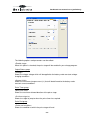
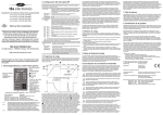
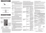
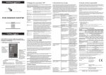
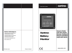
Dashboard user manual rev1e (preliminary)
User manual
Dashboard for Windows V1.1.0
TBS Electronics BV
De Factorij 46
1689 AL Zwaag
The Netherlands
www.tbs-electronics.com
COPYRIGHT © 2009 (rev1e)
-1-
Dashboard user manual rev1e (preliminary)
TABLE OF CONTENTS
1. INTRODUCTION . . . . . . . . . . . . .
2. INSTALLING DASHBOARD . . . . . . . . .
2.1 Getting started with the Dashboard software
3. EXPLAINING THE DASHBOARD ENVIRONMENT .
3.1 The Menu bar . . . . . . . . . . .
3.1.1 Menu bar – File . . . . . . . . . .
3.1.2 Menu bar – View . . . . . . . . .
3.1.3 Menu bar – ‘Device name’ . . . . . .
3.1.4 Menu bar – Tools . . . . . . . . .
3.1.5 Menu bar – Window . . . . . . . .
3.1.6 Menu bar – Help. . . . . . . . . .
4. BATTERY MONITOR CONTROL . . . . . . .
4.1 Battery monitor display panel . . . . . .
4.2 Battery monitor status . . . . . . . .
4.3 Battery monitor history . . . . . . . .
4.4 Battery monitor setup . . . . . . . .
5. BATTERY CHARGER CONTROL . . . . . . .
5.1 Battery charger display panel . . . . . .
5.2 Battery charger setup . . . . . . . .
5.2.1 The General tab . . . . . . . . . .
5.2.2 The Alarms tab . . . . . . . . . .
5.3 Charge Program Editor . . . . . . . .
5.3.1 The General tab . . . . . . . . . .
5.3.2 The Soft Start tab . . . . . . . . .
5.3.3 The Bulk tab . . . . . . . . . . .
5.3.4 The Ext. Bulk tab . . . . . . . . .
5.3.5 The Absorption tab. . . . . . . . .
5.3.6 The Analyze tab . . . . . . . . . .
5.3.7 The Float tab . . . . . . . . . . .
5.3.8 The Pulse tab. . . . . . . . . . .
5.3.9 The Equalize tab . . . . . . . . .
5.3.10 The Stop tab . . . . . . . . . .
5.3.11 The Error tab . . . . . . . . . .
6. END USER LICENSE AGREEMENT . . . . . .
-2-
.
.
.
.
.
.
.
.
.
.
.
.
.
.
.
.
.
.
.
.
.
.
.
.
.
.
.
.
.
.
.
.
.
.
.
.
.
.
.
.
.
.
.
.
.
.
.
.
.
.
.
.
.
.
.
.
.
.
.
.
.
.
.
.
.
.
.
.
.
.
.
.
.
.
.
.
.
.
.
.
.
.
.
.
.
.
.
.
.
.
.
.
.
.
.
.
.
.
.
.
.
.
.
.
.
.
.
.
.
.
.
.
.
.
.
.
.
.
.
.
.
.
.
.
.
.
.
.
.
.
.
.
.
.
.
.
.
.
.
.
.
.
.
.
.
.
.
.
.
.
.
.
.
.
.
.
.
.
.
.
.
.
.
.
.
.
.
.
.
.
.
.
.
.
.
.
.
.
.
.
.
.
.
.
.
.
.
.
.
.
.
.
.
.
.
.
.
.
.
.
.
.
.
.
.
.
.
.
.
.
.
.
.
.
.
.
.
.
.
.
.
.
.
.
.
.
.
.
.
.
.
.
.
.
.
.
.
.
.
.
.
.
.
.
.
.
.
.
.
.
.
.
.
.
.
.
.
.
.
.
.
.
.
.
.
.
.
.
.
.
.
.
.
.
.
.
.
.
.
.
.
.
.
.
.
.
.
.
.
.
.
.
.
.
.
.
.
.
.
.
.
.
.
.
.
.
3
3
3
4
5
5
5
5
6
7
7
7
7
7
7
7
7
8
8
8
10
11
12
13
15
17
19
21
23
24
26
28
29
30
Dashboard user manual rev1e (preliminary)
1. INTRODUCTION
Thank you for using Dashboard for Windows. Dashboard is a comprehensive software
platform, intended for configuration and readout of TBSLink enabled products from TBS
Electronics. It also offers a data logging feature capable of logging all available parameters
from your TBS product, for further analysis in for example Microsoft Excel. Dashboard shall
evolve continuously with the addition of new features and support for future products.
Currently, the following TBS products are supported :
- e-xpert pro(-hv) and e-xpert 501 battery monitors
- Powersine PS1000-PS1800 professional inverter series
- Omnicharge OC20-60 programmable automatic battery chargers
These TBS products must be connected to your Windows PC by either a USB or RS232
Communication kit (e-xpert series), or a USB to TBSLink Communication kit (Powersine and
Omnicharge series).
2. INSTALLING DASHBOARD
For information on the physical connections between the TBS product, the interface box and
the PC, please consult the installation guides that are supplied along with all TBS products.
If you connect to your PC using USB, please make sure that you only connect the USB
cable to your PC after Dashboard is completely installed.
Dashboard for Windows is compatible with Windows XP and Vista. Please follow the steps
below to ensure proper installation of the Dashboard communication software on your PC :
1) Exit all running Windows programs.
2) Insert the Dashboard communication software CD-Rom into your drive. The Autorun
capability of Windows will start the setup process automatically. If it does not, locate your
CD-Rom drive using Windows Explorer and run Setup.exe.
3) Follow the step-by-step instructions on your screen to complete the software installation.
NOTE : When you are not logged on with administrator privileges, Windows may ask you
for an administrator password a few times.
4) During installation, you may be asked to acknowledge installation of USB drivers twice.
5) After the software installation is completed, you can connect the USB interface box to a
free USB port on your PC.
2.1
Getting started with the Dashboard software
To start the Dashboard communication software after installing, proceed with the following
steps :
-3-
Dashboard user manual rev1e (preliminary)
1) Click on the Windows [START] button.
2) Select [PROGRAMS] followed by [Dashboard].
3) Choose the Dashboard icon to launch the software. When your battery monitor is
connected to the PC, a corresponding icon will appear in the Device manager.
3. EXPLAINING THE DASHBOARD ENVIRONMENT
The image below shows an example of the running Dashboard application :
Dashboard features a so-called MDI interface with a Device Manager on the left side and a
working area on the right side of the screen. When one or more devices are connected to
your PC, corresponding icons will appear in the Device Manager window. A double click on
one of these icons will launch a linked control panel in the working area. This control panel
shows real time data from the corresponding device. Depending on availability from the
corresponding device, up to three white buttons on the bottom side of the control panel will
activate the Status, History and Setup Windows. In the above image, the Setup window of an
e-xpert pro battery monitor is activated. Selecting an icon in the Device Manager will also
create a dedicated pull down menu in the menu bar.
-4-
Dashboard user manual rev1e (preliminary)
3.1
The Menu bar
The menu bar contains six pull-down menus, each offering a number of corresponding
execution commands.
3.1.1 Menu bar – File
<New Recording...>
Runs the recording wizard to start logging parameter data of your preferred device. Follow
the wizard instructions on your screen to setup the recording. During recording a small
three button control panel will appear in the working area. This panel will enable you to
stop, pause or restart your recording.
<Exit>
Closes the Dashboard application.
3.1.2 Menu bar – View
<Device Manager>
Check or uncheck the Device Manager to enable or disable its appearance on the screen.
<Status Bar>
Check or uncheck the Status Bar to enable or disable its appearance on the screen.
3.1.3 Menu bar – ‘Device name’ (e.g. ‘e-xpert pro’ or ‘OC12-60’)
Since the name of this pull-down menu is depending on the type of TBS product selected
in the Device Manager, the contents of this menu will also automatically adapt to this.
Currently, three TBS product types are supported in Dashboard and each corresponding
device name menu will be explained below :
If Device is a battery monitor (e-xpert pro or e-xpert 501) :
<Show Panel>
Launch the control panel in the working area.
<Status...>
Launch the selected device’s Status Window.
<History...>
Launch the selected device’s History Window.
<Setup...>
Launch the selected device’s Setup Window.
<Rename...>
Rename the selected device.
<Make Report...>
Create and save a text file that lists all status, history and setup data of the selected
device.
-5-
Dashboard user manual rev1e (preliminary)
If Device is a battery charger (e.g. OC12-60 or OC24-30) :
<Show Panel>
Launch the control panel in the working area.
<Setup...>
Launch the selected device’s Setup Window.
<Rename...>
Rename the selected device.
<Make Report...>
Create and save a text file that lists all status and setup data of the selected device.
<Standby mode>
Switches the battery charger from Normal- or Forced float mode to Standby mode.
<Normal mode>
Switches the battery charger from Standby- or Forced float mode to Normal mode.
<Forced float mode>
Switches the battery charger from Standby- or Normal mode to Forced float mode.
If Device is an inverter (e.g. PS1600-12 or PS1800-24) :
<Show Panel>
Launch the control panel in the working area.
<Rename...>
Rename the selected device.
<Make Report...>
Create and save a text file that lists all status and setup data of the selected device.
<Standby mode>
Switches the inverter from Normal- or ASB mode to Standby mode.
<Normal mode>
Switches the battery charger from Standby- or ASB mode to Normal mode.
<ASB mode>
Switches the battery charger from Standby- or ASB mode to Forced float mode.
3.1.4 Menu bar – Tools
<Charge Program Editor…>
Launch the charge program editor wizard to create or modify Omnicharge charge
programs (see chapter 5.3 for further explanation).
-6-
Dashboard user manual rev1e (preliminary)
3.1.5 Menu bar – Window
<Cascade>
Cascades all control panels in the working area.
<Tile>
Tile all control panels in the working area.
<Arrange All>
Arrange all control panels in the working area.
<Device name> (e.g. ‘1 e-xpert pro’ or ‘2 OC12-60’)
Choose which opened control panel gets focus.
3.1.6 Menu bar – Help
<View “User manual”>
Open this user manual (A PDF reader like Adobe Acrobat or Foxit Reader needs to be
installed on your system).
4. BATTERY MONITOR CONTROL
Dashboard allows display, setup and readout of all available parameters of the e-xpert
pro, e-xpert pro-hv and e-xpert 501 battery monitors.
4.1
Battery monitor display panel
<To be added later>
4.2
Battery monitor status
<To be added later>
4.3
Battery monitor history
<To be added later>
4.4
Battery monitor setup
<To be added later>
5. BATTERY CHARGER CONTROL
Dashboard allows display, setup and readout of all available parameters of your
Omnicharge battery charger. Additionally, Dashboard allows you to create new or modify
existing charge programs using the Charge Program Editor. This way the Omnicharge
battery charger can be adapted to all types of batteries.
-7-
Dashboard user manual rev1e (preliminary)
5.1
Battery charger display panel
Using the Show Panel command or by double clicking on the desired TBS product icon
in the device manager, a display panel will appear in the working area. The battery
charger display panel is shown below :
As you can see in the above picture, this display panel shows the charge progress bar,
the output current indication bar and a number of real time battery parameters.
5.2
Battery charger setup
Important : Battery charger setup by Dashboard is only possible when dipswitch 1
on the battery charger is set to ON (“EXT.”)
Using the Setup… command will launch the battery charger setup window.
5.2.1 The General tab
The battery charger setup window will open on the General tab as shown below :
-8-
Dashboard user manual rev1e (preliminary)
The General tab of the setup window allows the following settings :
Charge Program group
The charge program group shows the four available charge program banks of your
Omnicharge battery charger. You can select one of the desired default charge programs
or a custom made charge program saved in Program bank 4. The default Programs 1
(flooded), 2 (Gel) and 3 (AGM) cannot be replaced or edited. Program 4 can be edited or
replaced by pressing one of the two following buttons :
Press to load a previously saved charge program
Press to open the Charge Program Editor to modify the charge program
When any changes are made, you must always press the Ok button to transfer all
changed data to the battery charger. This also applies to transferring a new or modified
charge program to the charger. Pressing the Cancel button will close the setup window
without transferring any data to the battery charger.
General group
<Enable Buzzer>
Enable or disable the internal battery charger buzzer which sounds when activating the
charger or when the charge process is finished.
<AC fail memory time>
Shows the time that the battery charger will remember the charge stage in which it
-9-
Dashboard user manual rev1e (preliminary)
operated, after the AC mains has failed. This feature prevents the connected battery from
being overcharged by not starting the complete charge process again after a short AC
mains interruption.
5.2.2 The Alarms tab
The Alarms tab of the Setup window is shown below :
The following options and parameters can be edited :
Low Voltage Alarm group
<Enable alarm and use contact>
Shows if the battery low voltage alarm is enabled or disabled, as well as which alarm
contact will be activated. Please note that the Omnicharge battery chargers will not
charge batteries with a voltage lower than 1V/cell (6V @ 12V and 12V @ 24V battery
chargers), to avoid hazardous situations.
<Alarm on level>
Shows the voltage at which the low voltage alarm will be activated.
<Alarm off level>
Shows the voltage at which the low voltage alarm will be deactivated.
<Alarm on delay time>
Shows the time the Alarm on condition must be met before activating the alarm.
- 10 -
Dashboard user manual rev1e (preliminary)
High Voltage Alarm group
<Enable alarm and use contact>
Shows if the battery high voltage alarm is enabled or disabled, as well as which alarm
contact will be activated.
<Alarm on level>
Shows the voltage at which the high voltage alarm will be activated.
<Alarm off level>
Shows the voltage at which the high voltage alarm will be deactivated.
<Alarm on delay time>
Shows the time the Alarm on condition must be met before activating the alarm.
Low Temperature Alarm group
<Enable alarm and use contact>
Shows if the battery low temperature alarm is enabled or disabled, as well as which alarm
contact will be activated. This alarm will be deactivated automatically when the battery
temperature has risen 1°C above the ‘Alarm on level’.
<Alarm on level>
Shows the temperature at which the low temperature alarm will be activated.
High Temperature Alarm group
<Enable alarm and use contact>
Shows if the battery high temperature alarm is enabled or disabled, as well as which
alarm contact will be activated. This alarm can only be deactivated by resetting the battery
charger. This user intervention is needed to check whether the excessive temperature rise
was caused by the charging process or not.
<Alarm on level>
Shows the temperature at which the high temperature alarm will be activated.
5.3
Charge Program Editor
The Charge Program Editor can be launched in two ways. When it is desirable to create
or modify a charge program off-line (no battery charger connected to Dashboard), you can
use the Charge Program Editor Wizard which can be launched from the Tools menu. This
wizard will ask a few questions before entering the Editor window. Another way to launch
the Charge Program Editor is from the battery charger setup window (see chapter 5.2).
This is only possible when a battery charger is connected to Dashboard.
- 11 -
Dashboard user manual rev1e (preliminary)
CAUTION
The Charge Program Editor enables you to enter charge parameters
that may exceed the maximum ratings of your batteries. Take
extreme caution when editing charge parameters like absorption,
float or equalize voltages. Entering wrong values can damage your
batteries permanently or cause fire hazards. TBS Electronics BV is
not responsible for any damage caused by incorrect charge
program editing.
The Charge Program Editor allows you to create charge programs containing up to 10
different stages. These stages are named ‘Soft Start’, ‘Bulk’, ‘Ext. Bulk’, ‘Absorption’,
‘Analyze’, ‘Float’, ‘Pulse’, ‘Equalize’, ‘Stop’ and ‘Error’. All stages can be configured
independently using different tabs inside the Charge Program Editor window. The user
can also decide which stage to skip or not. For overall charge program settings, a
‘General’ tab is available as well.
5.3.1 The General tab
The Charge Program Editor window will open on the General tab as shown below :
Please note that when any changes are made, pressing the upper right Ok button will not
transfer the changed data to the battery charger yet. The actual data transfer can only be
executed by pressing the Ok button in the battery charger setup window. Press Cancel to
exit the Charge Program Editor without saving any settings or preparing it for later transfer
to the battery charger.
- 12 -
Dashboard user manual rev1e (preliminary)
When you wish to edit or create a charge program, but do not wish to transfer it yet to the
battery charger, press the Save to File… button to save all settings for later use.
When you wish to open the settings of an earlier made charge program, press the Open
File… button to select the desired file.
The following options and parameters can be edited :
Charge Program group
<Name>
Shows the name of the charge program that will be edited. The maximum length is 16
characters.
Temperature Compensation group
<Nominal battery temperature>
Shows the nominal battery temperature that will be used to calculate the correct
temperature compensation voltage.
<Temperature compensation>
Shows the rate of change of charge voltage versus measured battery temperature.
<Max. allowed negative compensation>
Shows maximum allowed charge voltage reduction controlled by measured battery
temperature.
<Max. allowed positive compensation>
Shows maximum allowed charge voltage rise controlled by measured battery
temperature.
Global Charge Timer group
<Max. charge time>
Shows the maximum allowed overall duration of a complete charge cycle.
<Max. timer start condition>
Shows the condition at which the maximum charge timer will start.
<On charge time-out go to>
Shows to which stage the charge program will jump when the maximum charger timer has
expired.
Start Up group
<First stage>
Shows the first stage at which the charge program will start when a new charge cycle is
initiated.
5.3.2 The Soft Start tab
The Soft Start stage is disabled in the factory default Flooded, GEL and AGM charge
- 13 -
Dashboard user manual rev1e (preliminary)
programs, but can be enabled in your custom charge program if it is desirable to for
example start the charge cycle with a lower charge current until a certain battery voltage
level is reached. The Soft Start tab is shown below :
The following options and parameters can be edited :
<Enable stage>
When this option is checked, the soft start stage will be enabled in your charge program.
Output Status group
<Voltage>
Shows the charge voltage which will be applied to the battery under constant voltage
charging conditions.
<Current Limit>
Shows the maximum charge current (%) that will be delivered to the battery under
constant current conditions.
Soft Start Timers group
<Min. soft start time>
Shows the minimum allowed duration of the Soft Start stage.
<Max. soft start time>
Shows the maximum allowed duration of the Soft Start stage.
<Max. timer start condition>
Shows the condition at which the soft start timer will start.
- 14 -
Dashboard user manual rev1e (preliminary)
<On time-out go to>
Shows the stage to jump to when the soft start timer has expired.
Soft Start End group
<Soft start end condition>
Shows the condition at which the Soft Start stage will end.
<Soft start end delay time>
Shows the time in which ‘Soft start end condition’ must be met, before the soft start stage
is considered to be finished.
<On soft start end go to>
Shows the stage to jump to when the soft start end condition has been met.
Alarm Status group
<Internal alarm contact>
The Omnicharge battery charger has one internal alarm contact designated as ‘[1]’. When
this option is checked, the internal alarm contact will be activated during the complete soft
start stage.
<External alarm contacts>
The Omnicharge battery charger is capable to control up to eight external alarm contacts.
With the optional Alarm Output Expander kit (art.# 5055630), three external alarm
contacts are available (‘[ ]1’, ‘[ ]2’ and ‘[ ]3’). Use this option to choose which external
alarm contact will be activated during the complete soft start stage.
5.3.3 The Bulk tab
The Bulk stage is enabled in the factory default Flooded, GEL and AGM charge
programs, but can be disabled in your custom charge program if desirable. The Bulk
tab is shown below :
- 15 -
Dashboard user manual rev1e (preliminary)
The following options and parameters can be edited :
<Enable stage>
When this option is checked, the bulk stage will be enabled in your charge program.
Output Status group
<Voltage>
Shows the charge voltage which will be applied to the battery under constant voltage
charging conditions.
<Current Limit>
Shows the maximum charge current (%) that will be delivered to the battery under
constant current conditions.
Bulk Timers group
<Min. bulk time>
Shows the minimum allowed duration of the bulk stage.
<Max. bulk time>
Shows the maximum allowed duration of the bulk stage.
<Max. timer start condition>
Shows the condition at which the bulk timer will start.
<On time-out go to>
Shows the stage to jump to when the bulk timer has expired.
- 16 -
Dashboard user manual rev1e (preliminary)
Bulk End group
<Bulk end condition>
Shows the condition at which the bulk stage will end.
<Bulk end delay time>
Shows the time in which ‘Bulk end condition’ must be met, before the bulk stage
is considered to be finished.
<On bulk end go to>
Shows the stage to jump to when the bulk end condition has been met.
Alarm Status group
<Internal alarm contact>
The Omnicharge battery charger has one internal alarm contact designated as ‘[1]’. When
this option is checked, the internal alarm contact will be activated during the complete bulk
stage.
<External alarm contacts>
The Omnicharge battery charger is capable to control up to eight external alarm contacts.
With the optional Alarm Output Expander kit (art.# 5055630), three external alarm
contacts are available (‘[ ]1’, ‘[ ]2’ and ‘[ ]3’). Use this option to choose which external
alarm contact will be activated during the complete bulk stage.
5.3.4 The Ext. Bulk tab
The Ext. Bulk (Extended Bulk-) stage is disabled in the factory default Flooded, GEL and
AGM charge programs, but can be enabled in your custom charge program if it is for
example desirable to split the Bulk stage into two, each charging at different end voltages
or current limit levels. The Ext. Bulk tab is shown below :
- 17 -
Dashboard user manual rev1e (preliminary)
The following options and parameters can be edited :
<Enable stage>
When this option is checked, the extended bulk stage will be enabled in your charge
program.
Output Status group
<Voltage>
Shows the charge voltage which will be applied to the battery under constant voltage
charging conditions.
<Current Limit>
Shows the maximum charge current (%) that will be delivered to the battery under
constant current conditions.
Ext. Bulk Timers group
<Min. ext. bulk time>
Shows the minimum allowed duration of the extended bulk stage.
<Max. ext. bulk time>
Shows the maximum allowed duration of the extended bulk stage.
<Max. timer start condition>
Shows the condition at which the extended bulk timer will start.
<On time-out go to>
Shows the stage to jump to when the extended bulk timer has expired.
- 18 -
Dashboard user manual rev1e (preliminary)
Ext. Bulk End group
<Ext. bulk end condition>
Shows the condition at which the extended bulk stage will end.
<Ext. Bulk end delay time>
Shows the time in which ‘Ext. bulk end condition’ must be met, before the extended bulk
stage is considered to be finished.
<On ext. bulk end go to>
Shows the stage to jump to when the extended bulk end condition has been met.
Alarm Status group
<Internal alarm contact>
The Omnicharge battery charger has one internal alarm contact designated as ‘[1]’. When
this option is checked, the internal alarm contact will be activated during the complete
extended bulk stage.
<External alarm contacts>
The Omnicharge battery charger is capable to control up to eight external alarm contacts.
With the optional Alarm Output Expander kit (art.# 5055630), three external alarm
contacts are available (‘[ ]1’, ‘[ ]2’ and ‘[ ]3’). Use this option to choose which external
alarm contact will be activated during the complete extended bulk stage.
5.3.5 The Absorption tab
The absorption stage is enabled in the factory default Flooded, GEL and AGM charge
programs, but can be disabled in your custom charge program if desirable. The
Absorption tab is shown below :
- 19 -
Dashboard user manual rev1e (preliminary)
The following options and parameters can be edited :
<Enable stage>
When this option is checked, the absorption stage will be enabled in your charge program.
Output Status group
<Voltage>
Shows the charge voltage which will be applied to the battery under constant voltage
charging conditions.
<Current Limit>
Shows the maximum charge current (%) that will be delivered to the battery under
constant current conditions.
Absorption Timers group
<Min. absorption time>
Shows the minimum allowed duration of the absorption stage.
<Max. absorption time>
Shows the maximum allowed duration of the absorption stage.
<Max. timer start condition>
Shows the condition at which the absorption timer will start.
<On time-out go to>
Shows the stage to jump to when the absorption timer has expired.
- 20 -
Dashboard user manual rev1e (preliminary)
Absorption End group
<Absorption end condition>
Shows the condition at which the absorption stage will end.
<Absorption end delay time>
Shows the time in which ‘Absorption end condition’ must be met, before the absorption
stage is considered to be finished.
<On absorption end go to>
Shows the stage to jump to when the absorption end condition has been met.
Alarm Status group
<Internal alarm contact>
The Omnicharge battery charger has one internal alarm contact designated as ‘[1]’. When
this option is checked, the internal alarm contact will be activated during the complete
absorption stage.
<External alarm contacts>
The Omnicharge battery charger is capable to control up to eight external alarm contacts.
With the optional Alarm Output Expander kit (art.# 5055630), three external alarm
contacts are available (‘[ ]1’, ‘[ ]2’ and ‘[ ]3’). Use this option to choose which external
alarm contact will be activated during the complete absorption stage.
5.3.6 The Analyze tab
The analyze stage is disabled in the factory default Flooded, GEL and AGM charge
programs, but can be enabled in your custom charge program if desirable. This stage can
for example be used to check the voltage response of the battery, after a certain charge
program stage has been applied to the battery.
The analyze stage will allow the battery voltage to drop, by disabling the charger’s output
and monitor if the battery voltage does not drop too deep within a certain amount of time.
The Analyze Timer group is used for determining the timeframe wherein the voltage drop
is monitored. The Analyze Fail group is used to detect if the battery voltage drops to deep.
In the example below, the analyze stage will take 2 minutes. If within this 2 minute
timeframe the voltage is not lower than or equal to 12.5V for 5 seconds, the charger will
jump to the float stage. If the voltage is lower than or equal to 12.5V for 5 seconds, the
charger will jump to the error stage.
The Analyze tab is shown below :
- 21 -
Dashboard user manual rev1e (preliminary)
The following options and parameters can be edited :
<Enable stage>
When this option is checked, the analyze stage will be enabled in your charge program.
Analyze Timer group
<Max. analyze time>
Shows the maximum duration of the analyze stage.
<On time-out go to>
Shows the stage to jump to when the ‘Max. analyze time’ has expired.
Analyze Fail group
<Analyze fail condition>
Shows the condition at which the analyze stage will fail.
<Analyze fail delay time>
Shows the time in which ‘Analyze fail condition’ must be met, before the analyze stage is
considered to be failed.
<On analyze fail go to>
Shows the stage to jump to when the analyze fail condition has been met.
- 22 -
Dashboard user manual rev1e (preliminary)
Alarm Status group
<Internal alarm contact>
The Omnicharge battery charger has one internal alarm contact designated as ‘[1]’. When
this option is checked, the internal alarm contact will be activated during the complete
analyze stage.
<External alarm contacts>
The Omnicharge battery charger is capable to control up to eight external alarm contacts.
With the optional Alarm Output Expander kit (art.# 5055630), three external alarm
contacts are available (‘[ ]1’, ‘[ ]2’ and ‘[ ]3’). Use this option to choose which external
alarm contact will be activated during the complete analyze stage.
5.3.7 The Float tab
The Float stage is enabled in the factory default Flooded, GEL and AGM charge
programs, but can be disabled in your custom charge program if desirable. The
Float tab is shown below :
The following options and parameters can be edited :
<Enable stage>
When this option is checked, the float stage will be enabled in your charge program.
Output Status group
<Voltage>
Shows the charge voltage which will be applied to the battery under constant voltage
charging conditions.
- 23 -
Dashboard user manual rev1e (preliminary)
<Current Limit>
Shows the maximum charge current (%) that will be delivered to the battery under
constant current conditions.
Float Timer group
<Max. float time>
Shows the maximum allowed duration of the float stage.
<On time-out go to>
Shows the stage to jump to when the float timer has expired.
Float End group
<Float end condition>
Shows the condition at which the float stage will end.
<Float end delay time>
Shows the time in which ‘Float end condition’ must be met, before the float stage is
considered to be finished.
<On float end go to>
Shows the stage to jump to when the float end condition has been met.
Alarm Status group
<Internal alarm contact>
The Omnicharge battery charger has one internal alarm contact designated as ‘[1]’. When
this option is checked, the internal alarm contact will be activated during the complete
float stage.
<External alarm contacts>
The Omnicharge battery charger is capable to control up to eight external alarm contacts.
With the optional Alarm Output Expander kit (art.# 5055630), three external alarm
contacts are available (‘[ ]1’, ‘[ ]2’ and ‘[ ]3’). Use this option to choose which external
alarm contact will be activated during the complete float stage.
5.3.8 The Pulse tab
The Pulse stage is enabled in the factory default Flooded, GEL and AGM charge
programs, but can be disabled in your custom charge program if desirable. This stage can
be used to deliver a short ‘refresh’ charge to the battery when it is connected to the
charger for an extended time. The Pulse tab is shown below :
- 24 -
Dashboard user manual rev1e (preliminary)
The following options and parameters can be edited :
<Enable stage>
When this option is checked, the pulse stage will be enabled in your charge program.
Output Status group
<Voltage>
Shows the charge voltage which will be applied to the battery under constant voltage
charging conditions.
<Current Limit>
Shows the maximum charge current (%) that will be delivered to the battery under
constant current conditions.
Pulse Timer group
<Max.pulse time>
Shows the maximum allowed duration of the pulse stage.
<On time-out go to>
Shows the stage to jump to when the pulse timer has expired.
Pulse End group
<Pulse end condition>
Shows the condition at which the pulse stage will end.
- 25 -
Dashboard user manual rev1e (preliminary)
<Pulse end delay time>
Shows the time in which ‘Pulse end condition’ must be met, before the pulse stage is
considered to be finished.
<On pulse end go to>
Shows the stage to jump to when the pulse end condition has been met.
Alarm Status group
<Internal alarm contact>
The Omnicharge battery charger has one internal alarm contact designated as ‘[1]’. When
this option is checked, the internal alarm contact will be activated during the complete
pulse stage.
<External alarm contacts>
The Omnicharge battery charger is capable to control up to eight external alarm contacts.
With the optional Alarm Output Expander kit (art.# 5055630), three external alarm
contacts are available (‘[ ]1’, ‘[ ]2’ and ‘[ ]3’). Use this option to choose which external
alarm contact will be activated during the complete pulse stage.
5.3.9 The Equalize tab
The Equalize stage is enabled in the factory default Flooded charge program and disabled
in the factory default GEL and AGM charge programs. Please make sure that if you wish
to enable this stage, you will only be charging battery types which are allowed to be
equalized. Sealed batteries can explode when equalizing these! Enabling the equalize
stage does not mean that the charger will automatically equalize your battery, but only
that it will respond to pressing the equalize switch at the bottom side of your Omnicharge
battery charger. The Equalize tab is shown below :
- 26 -
Dashboard user manual rev1e (preliminary)
The following options and parameters can be edited :
<Enable stage>
When this option is checked, the equalize stage can be activated by pressing the
recessed equalize switch at the bottom side of your Omnicharge battery charger. Please
note that the equalize stage can only be activated when the charger is operating in the
float or pulse stage.
Output Status group
<Voltage>
Shows the charge voltage which will be applied to the battery under constant voltage
charging conditions.
<Current Limit>
Shows the maximum charge current (%) that will be delivered to the battery under
constant current conditions.
Equalize Timers group
<Min. equalize time>
Shows the minimum allowed duration of the equalize stage.
<Max. equalize time>
Shows the maximum allowed duration of the equalize stage.
<Max. timer start condition>
Shows the condition at which the equalize timer will start.
<On time-out go to>
Shows the stage to jump to when the equalize timer has expired.
Equalize End group
<Equalize end condition>
Shows the condition at which the equalize stage will end.
<Equalize end delay time>
Shows the time in which ‘Equalize end condition’ must be met, before the equalize stage
is considered to be finished.
<On equalize end go to>
Shows the stage to jump to when the equalize end condition has been met.
Alarm Status group
<Internal alarm contact>
The Omnicharge battery charger has one internal alarm contact designated as ‘[1]’. When
this option is checked, the internal alarm contact will be activated during the complete
equalize stage.
- 27 -
Dashboard user manual rev1e (preliminary)
<External alarm contacts>
The Omnicharge battery charger is capable to control up to eight external alarm contacts.
With the optional Alarm Output Expander kit (art.# 5055630), three external alarm
contacts are available (‘[ ]1’, ‘[ ]2’ and ‘[ ]3’). Use this option to choose which external
alarm contact will be activated during the complete equalize stage.
5.3.10
The Stop tab
The stop stage is disabled in the factory default Flooded, GEL and AGM charge
programs, but can be enabled in your custom charge program if desirable. This stage can
be used to stop the charge process after the absorption stage, instead of going to the float
stage. In the error stage the charger output will be turned off. The Stop tab is shown below
:
The following options and parameters can be edited :
<Enable stage>
When this option is checked, the stop stage will be enabled in your charge program.
Stop Timer group
<Max. stop time>
Shows the maximum duration of the stop stage.
<On time-out go to>
Shows the stage to jump to when the ‘Max. stop time’ has expired.
- 28 -
Dashboard user manual rev1e (preliminary)
Stop End group
<Stop end condition>
Shows the condition at which the stop stage will end.
<Stop end delay time>
Shows the time in which ‘Stop end condition’ must be met, before the stop stage is
considered to be finished.
<On stop end go to>
Shows the stage to jump to when the stop end condition has been met.
Alarm Status group
<Internal alarm contact>
The Omnicharge battery charger has one internal alarm contact designated as ‘[1]’. When
this option is checked, the internal alarm contact will be activated during the complete
stop stage.
<External alarm contacts>
The Omnicharge battery charger is capable to control up to eight external alarm contacts.
With the optional Alarm Output Expander kit (art.# 5055630), three external alarm
contacts are available (‘[ ]1’, ‘[ ]2’ and ‘[ ]3’). Use this option to choose which external
alarm contact will be activated during the complete stop stage.
5.3.11
The Error tab
The error stage is not used in the factory default Flooded, GEL and AGM charge
programs. If from one of the above mentioned stages you have enabled a jump to the
error stage under certain conditions, you can use this tab to configure which alarm contact
will be activated. In the error stage the charger output will be turned off completely. To
restart the charger, the user needs to turn the power switch off and on again. The Error
tab is shown below :
- 29 -
Dashboard user manual rev1e (preliminary)
The following options can be edited :
Alarm Status group
<Internal alarm contact>
The Omnicharge battery charger has one internal alarm contact designated as ‘[1]’. When
this option is checked, the internal alarm contact will be activated until the user manually
resets the charger.
<External alarm contacts>
The Omnicharge battery charger is capable to control up to eight external alarm contacts.
With the optional Alarm Output Expander kit (art.# 5055630), three external alarm
contacts are available (‘[ ]1’, ‘[ ]2’ and ‘[ ]3’). Use this option to choose which external
alarm contact will be activated during the error stage.
6. END USER LICENSE AGREEMENT
IMPORTANT READ CAREFULLY
SOFTWARE PRODUCT here means Software, image files, all accompanying files, data and
materials received with your order of Dashboard.
Please read the following terms and conditions carefully before using this SOFTWARE
PRODUCT.
- 30 -
Dashboard user manual rev1e (preliminary)
By clicking on the “I ACCEPT” button, by opening the package that contains the SOFTWARE
PRODUCT, or by copying, downloading, accessing or otherwise using the SOFTWARE
PRODUCT, you agree to be bound by the terms of this License and you represent that you
are authorized to enter into this Agreement on behalf of your corporate entity (if applicable).
If you do not agree to any of the terms of this License or do not wish to be bound by the
terms of this License, click the “I DO NOT ACCEPT” button, and do not install, access, use
or distribute the SOFTWARE PRODUCT. Your use, distribution or installation of this copy of
this SOFTWARE PRODUCT indicates your acceptance of this License.
TBS Electronics BV is the owner of the copyright of this SOFTWARE PRODUCT. All of its
derivatives, title and accompanying materials are the exclusive property of TBS Electronics
BV. All rights of any kind, which are not expressly granted in this License, are entirely and
exclusively reserved to and by TBS Electronics BV. You may not rent, lease, transfer,
modify, translate, reverse engineer, de-compile, disassemble or create derivative works
based on this SOFTWARE PRODUCT. You may not make access to SOFTWARE
PRODUCT available to others in connection with a service bureau, application service
provider, or similar business. There are no third party beneficiaries of any promises,
obligations or representations made by TBS Electronics BV herein.
This SOFTWARE PRODUCT, all accompanying files, data and materials, are distributed "AS
IS" and with no warranties of any kind, whether express or implied. The user must assume all
risk of using the SOFTWARE PRODUCT. This disclaimer of warranty constitutes an
essential part of the agreement.
Any liability of TBS Electronics BV will be limited exclusively to refund of purchase price. In
addition, in no event shall TBS Electronics BV, or its principals, shareholders, officers,
employees, affiliates, contractors, subsidiaries, or parent organizations, be liable for any
incidental, consequential, punitive or any other damages (including, but not limited to,
procurement of substitute goods or services; Loss of use, data, or profits, or business
interruption) whatsoever relating to the use of SOFTWARE PRODUCT.
In addition, in no event does TBS Electronics BV authorize you to use this SOFTWARE
PRODUCT in applications or systems where SOFTWARE PRODUCT 's failure to perform
can reasonably be expected to result in a physical injury, or in loss of life. Any such use by
you is entirely at your own risk, and you agree to hold TBS Electronics BV harmless from any
claims or losses relating to such unauthorized use.
Warrantee covers defects in the SOFTWARE PRODUCT, which prevents successfully
installing the SOFTWARE PRODUCT on the buyer's computer provided that the buyer's
computer meets the SOFTWARE PRODUCT's minimum system requirements. Warrantee
does not cover fitness of purpose, not meeting of expectations or needs in the mind of the
buyer.
This SOFTWARE PRODUCT is for personal use only and may be installed and used by on
only one computer. Its component parts may not be separated for use on more than one
computer. SOFTWARE PRODUCT may be accessed through a network only after obtaining
a site license. All components accompanying the software are copyrighted by TBS
Electronics BV and may not be taken apart, modified, used or published with other software
or means except with the SOFTWARE PRODUCT software and may not be distributed or
copied in any manner.
You may not disclose to other persons the data or techniques relating to this SOFTWARE
- 31 -
Dashboard user manual rev1e (preliminary)
PRODUCT that you know or should know that it is a trade secret of TBS Electronics BV in
any manner that will cause damage to TBS Electronics BV.
This SOFTWARE PRODUCT and all services provided may be used for lawful purposes
only. Transmission, storage, or presentation of any information, data or material in violation
of the buyer's Country, State or City law is strictly prohibited. This includes, but is not limited
to: Copyrighted material, material we judge to be threatening or obscene, or material
protected by trade secret and other statute. You agree to indemnify and hold TBS Electronics
BV harmless from any claims resulting from the use of this SOFTWARE PRODUCT, which
may damage any other party.
This Agreement constitutes the entire statement of the Agreement between the parties on
the subject matter, and merges and supersedes all other or prior understandings, purchase
orders, agreements and arrangements. This Agreement shall be governed by the laws of
The Netherlands.
- 32 -