1
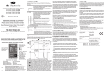
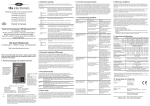
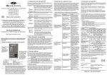
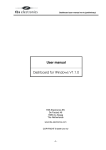
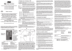
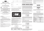
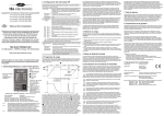
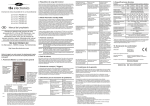
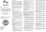
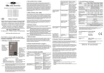
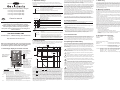
2. Dipswitch settings
During step 3 of the installation sequence, you can alter the factory settings of the
dipswitches to change the charger’s functionality on a few points. The following settings
can be made :
: Choose to configure the battery type locally (using dipswitch 2 and
3), or override these settings and setup the charger externally using
the TBS Dashboard for Windows software.
1. LOC. / EXT.
Professional programmable battery chargers
omnicharge OC12-40 (12V-40A)
omnicharge OC12-60 (12V-60A)
omnicharge OC24-20 (24V-20A)
omnicharge OC24-30 (24V-30A)
Owner’s manual
EN
Thank you for purchasing a TBS Electronics
professional programmable battery charger.
Please read this owner’s manual for information
about using the product correctly and safely.
Keep this owner’s manual close to the charger for
future reference.
on
Setting ON : The local dipswitch settings of dipswitch 2 and 3 are ignored and
configuration must be done externally.
1
on
Setting OFF : The local dipswitch settings are used (factory default).
1
2 & 3. BATTERY
TYPE
DS2
DS3
on
on
2
3
on
on
2
3
on
on
2
3
on
on
2
3
!
CAUTION
: Select the type of lead-acid battery that you wish to charge. Each
setting represents the best charging voltages for the given battery
type listed below. If there are still other voltage levels or different
charging programs needed for your battery, please use the TBS
Dashboard software to create your own and store this as Custom
setting inside the charger.
BATTERY TYPE (12V/24V)
Before you start to charge batteries, read all enclosed safety instructions and warnings
while following all safety precautions about working with batteries.
AGM
absorption voltage 14.3V/28.6V, float voltage 13.3V/26.6V
The list below globally describes the steps to follow for charging batteries :
Custom
not available when dipswitch 1 is set to OFF (LOC.)
Invalid battery type settings can cause serious damage to your batteries and/or
connected battery loads. Always consult your battery’s documentation for the
correct charge voltage settings.
Setting ON
: remote switch connection terminals are bypassed (factory default).
Setting OFF
: remote switch connection terminals are open. A remote switch
must be connected and switched ON in order to activate the
charger. The local on/off switch on the frontpanel always overrides
the remote switch. So in order to use the remote switch, the local
on/off switch must be in the 'power on' or 'forced float’ position.
4
3. Charge programs
Before proceeding with this owner’s manual, please make
sure you have carefully read the enclosed safety flyer and
the installation guide on the backside of this paper!
All standard selectable charge programs (using dipswitches 2 and 3), perform a four stage
IUoUoP charging process comprising of a “Bulk” , an “Absorption”, a “Float” and a “Pulse”
stage. The image below visualizes the four stage charging process :
Bulk
Absorption
Pulse
Float
Float
Bulk
V(12V)
1. Omnicharge display and control overview
Charge status bar
V(24V)
14.4V
28.8V
13.5V
12.5V
27.0V
25.0V
battery load
turned on
(Iload>Imax)
A rough indication of the
charging progress.
output current bar
80% full
indicates the percentage of delivered
output current.
50% full
empty
“power on, off, forced
float” switch
When in position “O” the
1)
charger is off .
When switched to “I” the
charger switches on in
normal charging mode.
When switched to “II” the
charger operates in
forced float mode. See
chapter 5 for more details
on the forced float mode.
indicator mode :
description :
continuous green
flashing red (1 flash per sec.)
flashing red (2 flashes per sec.)
flashing red (3 flashes per sec.)
flashing red (4 flashes per sec.)
power on, normal operation
2)
battery error
charger overload
high charger temperature 3)
charger error (return for service)
When the switch is in position “O”, it does not interrupt any internal AC or DC sources.
This means that there are still lethal voltages present inside the charger! In position “O”,
the charger will still consume a small amount of AC current.
A battery error can appear for several reasons. These are : battery voltage is too
low (too deeply discharged) or too high and battery temperature is too low or too high
(only available when battery temperature sensor is connected). The charger will not
restart automatically in battery error mode, except when this error was generated due to a
too low battery voltage or a too low battery temperature.
The charger automatically restarts when the temperature is below an acceptable level.
absorption time-out
max. 4hrs
Ich
float time-out
7 days
pulse
1hr
5. Forced float mode
This warranty will not apply where the product has been misused, neglected, improperly
installed or repaired by anyone other than TBS. TBS is not responsible for any loss,
damage or costs arising from improper use, use in an unsuitable environment, improper
installing of the charger and charger malfunctioning.
Since TBS cannot control the use and installation (according to local regulations) of their
products, the customer is always responsible for the actual use of these products. TBS
products are not designed for use as cricital components in life support devices or
systems, that can potentially harm humans and/or the environment. The customer is
always responsible when implementing TBS products in these kind of applications. TBS
does not accept any responsibility for any violation of patents or other rights of third
parties, resulting from the use of the TBS product. TBS keeps the right to change product
specifications without previous notice.
1)
Examples of improper use are :
- Too high AC input voltage applied
- Connecting wrong batteries (too high battery voltages)
- Mechanical stressed enclosure or internals due to harsh handling and/or incorrect
packaging
- Contact with any liquids or oxidation caused by condensation
9. Declaration of conformity
:
De Marowijne 3
1689 AR Zwaag
The Netherlands
6. Equalizing a flooded battery
Declares that the following products :
If you are using a flooded lead acid battery, an occasional equalization charge cycle may
be recommended by the manufacturer. This might also be true when the flooded battery
has been very deeply discharged or often charged inadequately. During equalization, the
battery will be charged up to 15.5V (or 31V for 24V models) at a reduced output current
level. Before starting an equalization charge cycle, the following caution statements must
be read carefully :
Equalization should only be performed on a flooded (wet) lead acid battery.
Therefore the Omnicharge chargers only allow equalization when the battery
CAUTION
type dipswitches are set to Flooded. Other battery types like GEL or AGM will be
damaged by this process.
!
!
!
Always follow the battery manufacturer's instructions when equalizing flooded
batteries.
During equalization, the battery generates explosive gasses. Follow all the battery
safety precautions enclosed with your charger. Ventilate the area around the
battery sufficiently and ensure that there are no sources of flames or sparks in the
Disconnect all loads connected to the battery during equalization. The voltage
applied to the battery during this process may be above safe levels for some loads.
The Omnicharge chargers cannot automatically determine when to stop the
equalization of a battery. The user must monitor the battery’s specific gravity
throughout this process to determine the end of the equalization cycle. The internal
2 hours time-out timer of your charger is only intended as a safety feature, but may not be
sufficiently short to prevent battery damage. Therefore, equalizing a battery is always a
process that must continuously be supervised by the user.
!
CAUTION
10% Imax
t
This warranty is void if the charger has suffered any physical damage or alteration, either
1)
internally or externally, and does not cover damage arising from improper use , or from
use in an unsuitable environment.
ADDRESS
CAUTION
In the Bulk stage, the charger delivers full output current and typically returns
approximately 80% of charge back into the battery once the absorption voltage is reached.
During this stage, indicators
and
will be lit depending on the Bulk charge progress.
When the absorption voltage has been reached, the Absorption stage will be entered and
indicator
will be lit. This stage will return the final 20% of charge to the battery. The
output voltage is kept at a constant level and the charge current decreases as a function of
the battery's state of charge. When the charge current has dropped below a certain value
or when the maximum absorption timer has been expired, the Float stage will be entered.
Indicator
will be lit and an acoustical message will sound, indicating that the battery is
full. In this stage the battery voltage will be held constant at a safe level for the battery. It
will maintain the battery in optimal condition for as long as the battery remains connected
to the activated charger. Connected battery loads will be directly powered by the charger
up to the charger's maximum output current level. When even more current is drawn, the
battery must supply this which results in a declining battery voltage. At a certain battery
voltage level, the charger jumps back to the Bulk stage and will finalize a complete three
stage charging process again, once the battery load consumption has dropped below the
charger's maximum output current level.
TBS Electronics (TBS) warrants this charger to be free from defects in workmanship or
materials for 24 months from the date of purchase. During this period TBS will repair the
defective charger free of charge. TBS is not responsible for any costs of the transport of
this charger.
TBS Electronics BV
vicinity.
Imax
8. Warranty conditions
:
CAUTION
global charge time-out
max. 8hrs
This charger is equipped with a potential free alarm relay. This relay will be activated when
the charger shuts down and jumps to an error mode as described in chapter 1. The alarm
relay de-activates again when the error mode has been cleared and the charger is running
in normal operating mode again. On pins 1,2 and 3 of the 5 pins screw terminal located in
the connection compartment, both normally closed and normally open contacts are
available. Please make sure not to exceed the maximum relay contact rating of 60V and
1A to avoid damaging the relay.
MANUFACTURER
CAUTION
t
7. Alarm relay
The forced float mode can be activated by pushing the main switch into position “II”. In this
mode, the output voltage of the charger is set constantly to the float voltage (value is
depending on selected battery type) while being able to deliver full rated output current.
Since no automatic charging programs are activated in this mode, it can be used for
constant voltage charging or operating the charger as a battery buffered power supply.
!
restart three stage
charging process
100% full (ready)
note 3 :
1. Push the charger switch in the “O” (Off) position and disconnect the AC supply to the
charger
2. If possible disconnect or switch off all loads from the battery
3. Connect the battery to the charger
4. Switch on the AC supply and activate the charger by pushing the charger switch in the
“I” (power on) position. After a two tone beep, the charger will start the charging proces.
5. After charging is completed, push the charger switch in position “O” and switch off the
AC supply again, before disconnecting the battery. Or, keep all connections and the
charger switch position untouched and just re-connect all battery loads.
4
http://www.tbs-electronics.com
note 2 :
The Auxiliary battery output always follows the charge process of the Main battery
automatically. You can use this output to charge a second (smaller) battery, like a starter
battery. It is not possible to use this output when the Main battery is not connected!
4. Charging batteries
on
De Marowijne 3, 1689AR, Zwaag, The Netherlands
note 1 :
When the standard selectable charging programs do not satisfy your requirements, or
when different voltage- and current levels are needed, you can use the optional TBSLink
communication kit and create your own charge programs using TBS Dashboard. Up to 8
different stages can be linked together and all individual stages can be configured
extensively. Please contact your TBS equipment supplier for further information on the
TBSLink communication kit.
GEL
absorption voltage 14.2V/28.4V, float voltage 13.5V/27.0V
on
“charger on” or “error” indicator
When the battery temperature sensor is installed, the charger automatically compensates
the charge voltages against battery temperature. This means that the charge voltages are
slightly increased at lower temperatures and decreased at higher temperatures (-30mV/°C
at 12V chargers and -60mV/°C at 24V chargers). This way, overcharging is prevented
which prolongs your battery's lifetime. A connected battery temperature sensor also
enables the battery temperature protection, which stops the charging process when the
battery's temperature is below -20°C or above +50°C.
Flooded (factory default)
absorption voltage 14.4V/28.8V, float voltage 13.5V/27.0V
4. BYPASS REMOTE : Bypasses the remote switch connection when no remote switch is
SW.
connected.
TBS ELECTRONICS BV
The fourth stage called “Pulse”, will perform a short refresh charge of approximately 1 hour
each 7 days while the charger operates in the Float stage. This will keep the battery in
optimal condition while prolonging it's lifetime. The battery can remain connected to the
activated charger continuously, without risk of overcharging.
!
CAUTION
When equalizing the main battery, the smaller battery connected to the auxiliary
battery output will be equalized as well. When this is not desirable, please
disconnect this battery before starting the equalization cycle.
Since equalization is only allowed for flooded (wet-) lead acid batteries, the Omnicharge
chargers will only allow this function to be available when the “Flooded” charging program
is selected (see chapter 2). Besides this, the charger also needs to have a full charge cycle
completed and is operating in the Float mode. When these two conditions are met, the
equalization charge mode can be activated by pressing the recessed pushbutton on the
bottom side of the charger (see installation guide step 4) for 3 seconds until all charge
status indicators start flashing. The charger will allow a maximum equalization time of 2
hours before it automatically jumps back to Float mode. If the specific gravity of each cell
does not match the battery manufacturer's specifications yet, you can initiate a new 2 hours
equalization cycle by pressing the pushbutton for 3 seconds again. Always keep on
checking the specific gravity of each cell repeatedly during the equalization process. When
these values are correct, you can manually exit the equalization process by pressing the
recessed pushbutton once. The charger will then return to the Float mode.
PRODUCT TYPE
MODELS
:
:
Professional programmable battery charger
OC12-40, OC12-60, OC24-20, OC24-30
Conforms to the requirements of the following Directives of the European Union :
EMC Directive 2004/108/EC
Low Voltage Directive 2006/95/EC
The above product is in conformity with the following harmonized standards :
EN61000-6-3 : 2001 EMC - Generic Emissions Standard
EN61000-6-2 : 2005 EMC - Generic Immunity Standard
EN60335-1 : 1999
Generic safety standard
EN60335-2-29 : 2004 Safety requirements for battery chargers
GB
INSTALLATION GUIDE
- Please read this document very carefully to avoid charger malfunction, shock and/or fire hazards!
- This document provides a brief overview of a stand alone charger installation. For long term safe and troublefree operation, it is very important to read the owner’s manual on the rear side of this paper as well!
- Please follow the exact installation sequence as given below. Skipping one or more steps could result in charger malfunctioning or shock and/or fire hazards!
= Approved
2 CHARGER MOUNTING
1 UNPACKING
= Not recommended
3 CONNECTION COMPARTMENT WIRING DETAILS
The charger package should contain the
following items :
For explanation on the dipswitch settings,
please consult chapter 2 of the owner’s
manual.
- Battery charger
- 5m temperature sensor
- This Installation guide / Owner's manual
- Safety flyer
- WEEE flyer
!
- 2x M8 crimp terminals.
Access the connection compartment
by removing the two screws and
sliding the red cover downwards.
- 4x Mounting screws.
After unpacking, check if the
charger shows any mechanical
CAUTION
damage. Never use the charger
when the enclosure shows any visual
damage caused by harsh handling, or
when it has been dropped accidentally.
Contact your local supplier for further
information.
!
vertical wall mounting
(IP21)
vertical wall mounting
(upside down)
horizontal wall mounting
CAUTION
PE / EARTH
+60V max.
Fuse
334mm
Fuse
Use a wire size of
2
Ø1.5mm (AWG15) or
larger for the AC wires
- (return)
ceiling mounting
CAUTION
CAUTION
Always connect the negative (-) cable directly on the negative terminal of the battery, or
on the “loadside” of a current shunt. Always keep positive and negative cables close to
each other to minimize electromagnetic fields.
!
!
126mm
Alarm outputs
Temp.sensor/
Data output
Data
input
9
>
OC20-60 Manual Rev2e / Printed in The Netherlands
0-6m(0-20ft)
All :
2.5mm²(AWG13)
Technical specifications
Parameter
OC12-40
OC12-60
OC24-20
OC24-30
charger is not working (all
indicators are off).
Power switch in OFF (0)
position.
Push the power switch in the
‘I’ or ‘II’ position.
‘High charger temperature
error’ keeps on appearing.
Airflow around the charger
is obstructed.
Full load consumption
700VA
1050VA
700VA
1050VA
AC input current (115V/230V)
6A/3A
9A/4.5A
6A/3A
9A/4.5A
No or too low AC input
voltage.
Check AC wiring and input
voltage level.
Make sure there is at least
10 centimeters of clearance
around the charger. Remove
any items placed on or over
the charger. Keep the
charger away from direct
sunlight or heat producing
equipment.
88%
91%
Move the charger to a cooler
environment or provide
additional cooling by an
external fan.
Absorption voltage2)
14.4V
28.8V
Float voltage2)
13.5V
27.0V
Equalize voltage2)
15.5V
31.0V
Please return the charger to
your nearest dealer for
service.
Supported Battery types2)
The charge voltage is being
compensated by the battery
temperature sensor to
protect your battery.
Do nothing or try to cool
down the ambient
temperature around the
battery.
Operating temp. range4)
-20°C … +50°C (humidity max. 95% non condensing)
Storage temp. range
-40°C … +80°C (humidity max. 95% non condensing)
Cooling
Variable speed fan controlled by temperature and load
Wrong charge program
selected by the dipswitches
or custom charge program
needs to be re-adjusted.
Select the correct charge
program or adjust the
custom charge program
using TBS ‘Dashboard’.
TBSLink enabled
Yes
Protected against
Low AC voltage, output short circuit, high temperature,
battery overcharging and reverse polarity (fuse)
DC cables too thin.
Install larger DC cables. See
the DC cable size table in
the installation guide.
Battery voltage is too low or
too high.
Check the battery for
damaged or shorted cell(s).
Check if DC bus voltage is
being pushed by another
charging device.
Check low or high battery
voltage alarm settings using
TBS ‘Dashboard’.
Battery temperature is too
low or too high (only
relevant when the battery
temperature sensor is
installed).
Check and try to correct the
ambient temperature around
the battery.
Check if the temperature
sensor is not damaged.
There is a short circuit on
the charger output.
Check DC wiring.
Check battery condition.
Charger is being
overloaded in ‘Forced float’
mode.
When the charger is used in
‘Forced float’ mode without a
battery attached (not
recommended), try to reduce
the load.
Note : Do not turn off the
charger when it's operating
in an ‘High temperature
error’. The charger needs
this error time to cool down.
‘Charger error’ keeps on
appearing.
Charge voltage is too low.
Too high ambient
temperature.
An internal error is
detected.
Input voltage
Full load efficiency
Battery load current is
higher than the charger’s
output current.
Reduce or remove the
battery load.
High ambient temperature.
Try to cool down the ambient
temperature around the
charger.
Charger is operating in the
absorption charging stage.
Do nothing. The battery is
almost fully charged and
consumes less current by
itself.
100-260VAC / 47-63Hz / PF ³ 0.95
88%
Nominal output voltage1)
Total output current1) 4) (Aux.)
Charge characteristic2)
Recomm. battery capacity3)
DC current draw (charger off)
Indications
Charge current is too low.
Alarm Output Expander (optional)
Model
Remedy
‘Charger overload’ or
‘Battery error’ keeps on
appearing.
>
Auxiliary battery cable sizes :
Possible cause
MAIN BATTERY
- External 1
- External 1
- External 1
- External 2
- External 2
- External 2
- External 3
- External 3
- External 3
16mm²(AWG5) / 25mm²(AWG3)
25mm²(AWG3) / 35mm²(AWG2)
6mm²(AWG9) / 10mm²(AWG7)
10mm²(AWG7) / 16mm²(AWG5)
Problem
WARNING
NO
NC
CM
NO
NC
CM
NO
NC
CM
OC12-40 :
OC12-60 :
OC24-20 :
OC24-30 :
Remedy
Always connect the temperature
sensor on the minus terminal of
the main battery!
1
<3m(10ft) / 3-6m(10-20ft)
Possible cause
Universal Remote Control (optional)
Alarm output
expander
Model
Problem
‘Battery error’ keeps on
appearing.
art.# : 5055630
MAIN BATTERY
Troubleshooting guideline
Activate the charger
Remote switch or remote
control have deactivated the remotely or check dipswitch
4 for correct setting.
charger.
<
AUXILIARY OR
STARTER
BATTERY
(OPTIONAL)
Double check for correct
polarity, before connecting the
battery cables to the battery!
drilling template
Alarm terminals
Main battery cable sizes :
Alarm indicator
light (1A max.)
Black cable
L1
Battery temperature sensor for
temperature compensated charging
1A fuse
Red cable
N
Recessed pushbutton location to activate or
deactivate the equalisation charge mode (see
chapter 6 of the owner’s manual)
Remote on/off
switch
use Ø1mm2 (AWG17) wire size
GFCI/RCD
4 BOTTOM SIDE CONNECTIONS
When all connections are made and
double checked, slide the red
connection compartment cover to it’s
original position again and relocate
the two screws.
max. length 50m (150ft)
This charger must
be earthed. Always
connect the PE wire!
WARNING
187mm
floor mounting
Please feed all connection
compartment wiring through the
rubber grommets and plastic gland.
DC output connections
40A(4A)
24V
60A(4A)
20A(2.5A)
Flooded / GEL / AGM / Custom
80-400Ah
120-600Ah
50-200Ah
£ 5mA
Power on, output current bar, state of charge bar, error
M8 bolts (main output), Screw terminals (auxiliary output)
Screw terminals
351 x 210 x 114mm
Standards
70-300Ah
£ 4mA
Enclosure body size
Protection class
30A(2.5A)
IUoUoP, intelligent 4-stage, temperature compensated
AC input connections
Total weight
91%
12V
5.8 kg
IP21 (mounted in upright position)
CE marked meeting EMC directive 2004/108/EC and
LVD 2006/95/EC complying with EN60335-1, EN603352-29
Note: the given specifications are subject to change without notice.
1)
Maximum output current tolerance is +/-3%. Maximum setpoint voltage deviations are +/- 0.1V for 12V
and +/- 0.2V for 24V models. All setpoint voltages are temperature compensated when battery
temperature sensor is connected.
2)
Value is programmable
3)
Always consult battery manufacturers specifications for maximum allowable charge current
4)
At higher ambient temperatures (>40°C), maximum output current may be reduced automatically