1
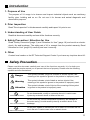
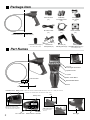
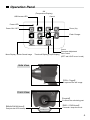
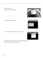
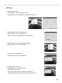
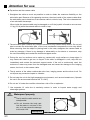
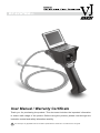
User Manual / Warranty Certificate
Thank you for purchasing the product. This document includes the important information
to ensure safe usage of the product. Before using the product, please read through this
instruction manual and safety information carefully.
The warranty is only applicable when the unit fails to operate with the normal use in accordance to the user guide.
Tablet of Content
Introduction … …………………………………………………… 2
Safety Precaution ………………………………………………… 2
Package Item ……………………………………………………… 3
Part Names ………………………………………………………… 3
Operation Panel … ……………………………………………… 4
Preparation ……………………………………………………… 5
Prior Inspection … …………………………………………………………… 5
Insert the Batteries…………………………………………………………… 5
Insert the Micro SD Card … ………………………………………………… 5
With the AC Adapter … ……………………………………………………… 5
Basic Operation … ……………………………………………… 6
Turn ON / OFF the Power …………………………………………………… 6
Display the Image … ………………………………………………………… 6
Save the Image… …………………………………………………………… 7
Display the stored Image… ………………………………………………… 8
Delete the Stored image / Adjust the Image Quality… ………………… 9
Features… …………………………………………………………………… 11
View Image with Computer… ………………………………… 15
install USB driver……………………………………………………………… 15
Confirm USB Driver Installation… ………………………………………… 17
Viewer Software ……………………………………………………………… 18
Attention foe use… ……………………………………………… 23
Tip section and the camera cable… ……………………………………… 23
Waterproof property… ……………………………………………………… 23
Maintenance… …………………………………………………… 24
Q&A(Troubleshooting)………………………………………… 25
Specitications… ………………………………………………… 26
Camical Compatibility………………………………………………………… 26
Warranty Terms … ……………………………………………… 27
Warranty Certificatt ……………………………………………… 27
1
Introduction
1. Purpose of Use
The purpose of VJ usage is to observe and inspect industrial objects such as machinery,
facility, pipe, building and so on. Do not use it for human and animal diagnostic and
observation purpose.
2. Prior Inspection
Read "Prior Inspection" in this document carefully and inspect VJ prior to use.
3. Understanding of User Guide
Read this document carefully and use all the functions correctly.
4. Safety Precaution / Attention for Use
Read "Safety Precaution"(page 2) and "Attention for Use" (page 19) and avoid an electric
shock, fire and breakage. The cable part of VJ is exempt from the product warranty. Read
"Attention for Use" (page 19) carefully and use it correctly.
5. Other
Contact local vender or the RF Technical Support Center if you have any inquiries about VJ.
Safety Precaution
Please read this document carefully and use all the functions correctly. It is for both your
safety and the people around you to prevent the loss of property. Please refer the following
symbols and documentations.
Danger
This symbol indicates a high risk of death or serious injuries if the
meaning of this symbol is ignored or the product is improperly used.
Warning
This symbol indicates a risk of death or serious injuries if the
meaning of this symbol is ignored or the product is improperly used.
Attention
This symbol indicates a risk of injuries if the meaning of this symbol
is ignored or the product is improperly used.
Disassemble Prohibited
Do not disassemble, modify or customize the unit. It could cause
injuries by an electric shock or failure of the unit.
Direct Contact Prohibited
Do not touch any internal components exposed by the damage on
the outer casing. It could cause injuries by an electric shock or its
breakage.
Water Contact Prohibited
Do not pour, splash or immerse the unit in water. Do not leave the unit
out in the rain. It could cause a fire or electric shock.
2
Package Item
Insertion Tube (x1)
Micro SD Card
(x1)
AA Battery
for Operation Test
(x4)
AC Adaptor
6V / 0.85A
(x1)
DC Video Cable
(x1)
USB Cable
(x1)
Driver CD-ROM
(x1)
Main Unit (x1)
Protective Lens Cap (x1)
*It is worn prior to ship.
Part Names
Hands-Free
Microphone (x1)
Sun Visor (x1)
Mounting Screw (x2)
Stand (x1)
Stand Mounting Screw (x1)
*It is mounted prior to ship.
*With Sun Visor
3.5 inch
Color Digital TFT Monitor
Operation Panel
Joystick
REC / STOP Button
Camera Head
BRIGHTNESS Button
Articulating Part
Insertion Tube
Stand
Main Unit
Protective Cover Battery Cover *Micro SD card slot is located inside the battery cover. DC / Video jack and USB
connector are located under the protective rubber cover.
Cap
Battery Case
Stand Mounting Screw
*Remove the screw to detach
the stand from the main unit.
3
DC / Video Jack
Audio Input Jack
Micro SD
USB Connector Card Slot
*It is located under
the cap.
Still Trigger
Operation Panel
OK
(Temperature Display)
USB Access LED
Cancel
Power LED
Power ON / OFF
Zoom (2x)
Flash Charger
Menu Display / Delete Stored Image
Cursor
Parameter Adjustment
Gain Control
Thumbnail Display (9-split Display)
(LEFT and LIGHT cursor is used)
Side View
【STILL Trigger】
It captures the still image.
Front View
【Joystick】
It controls the articulating part.
【BRIGHTNESS Button】
It adjusts the LED intensity.
【REC / STOP Button】
It records / stops the movie.
4
Preparation
Prior Inspection
(1) Inspect Insertion Tube
■ Check the insertion tube does not have any change in shape or defect in appearance.
■ Check the glass of camera head has any dart or stain. Please wipe out with dry cloth if there is any.
(2) Inspect Articulating Part
■ Check the articulating part moves smoothly.
■ Check the articulating part does not have any change in shape or defect in appearance.
Insert the Batteries
(1) Open the battery cover.
(2) Insert AA batteries.
❷
❶
Attention
❶Slide the battery cover
❷Open the battery cover
マイクロSDカードを入れる
Insert
the Micro SD Card
- Watch the direction of the batteries.
The unit indicates the proper direction of the batteries.
- Compatible battery type
Use an alkaline or rechargeable nickel hydride battery.
The unit may not function properly with a manganese dioxide battery.
Insert the included micro SD card into the micro SD card slot.
*It is necessary to store the images.
(The unit can be operated without the micro SD card.)
Attention
YES
NO
- Be sure to turn off the power when the micro SD card
is inserted / removed.
- Compatible micro SD card type
Use a micro SD card less than 2GB memory with the micro SD logo.
Any micro SDHC card cannot be used.
- Insert the micro SD card at a slant position may cause
damage or failure on the card slot. Be sure to insert straightforward.
With the AC Adapter
- Plug the included AC adapter (6V / 0.85A) to the DC / Video jack.
- When the unit is used with the AC adapter, the battery power will
not be consumed.
To Video Input Jack
DC / Video Jack
5
DC / Video Cable
AC Adapter
To Electric Outlet
Basic Operation
Power ON / OFF Button
Turn ON / OFF the Power
Power LED
Press and hold the power button for 1 second.
The power LED lights up in green and the live image will be displayed
on the monitor.
Press and hold the power button again for 1 second.
The power of the unit and power LED will turn off.
Battery Run-time
Power LED
AA battery: Total run-time 1.5 hours
(With rechargeable nickel hydride battery: 2.5 hours)
- The Power LED flashes in red if the remaining battery power
reaches less than 5%. In this case, all buttons operation become
ineffective besides the Power ON / OFF button.
■ Green ••••••••••• Power ON
The remaining battery power: 20∼100%
■ Orange ••••••••• Power ON
The remaining battery power: 5∼20%
■ Red ••••••••••••• The remaining battery power: Less than 5%
■ OFF •••••••••••• Power OFF
■ Flashing •••••• Accessing the micro SD card
(Recording or playing video)
Display the Image
■ With the 3.5" color digital TFT monitor:
The live image is displayed on the 3.5" color TFT monitor, when the power is turned on.
■ With other monitor:
Connect the included DC / Video power cable between the DC / Video jack on the unit and the
video input jack on the monitor.
Attention
Be sure to securely plug
the cables into the jacks.
Other monitor
DC / Video Jack
To video Input Jack
To AC Adapter (with the AC Adapter)
DC / Video Cable
6
Save the Image
Save the Still Image
■ Press the STILL trigger to capture the still image.
*The micro SD card must be inserted for this operation.
STILL Trigger
■ When the still image is saved, the monitor shows the message,
"JPG FILE SAVED".
*The "2x Zoom Display function" is only available on the 3.5" color digital
TFT monitor. The still image is saved in ordinary size.
Record the Video
■ Press the REC / STOP button to start recording the video. To stop
recording, press the REC / STOP button again or EIXT button.
*The micro SD card must be inserted for this operation.
*The Power LED flashes while the video is recorded.
*The frame rate varies depending on the recording video, memory
capacity of the micro SD card or data transfer speed.
REC/STOP
When recording the video
■ The screen shows the message,
"BEGIN AVI RECORDING"
when the recording starts.
When saving the video
■ The screen shows the message,
"SAVING AVI FILE"
when the recording stops.
■ When the micro SD card is not inserted, the message,
"NO SD CARD" is displayed, and the unit does not store any image.
■ When the micro SD card is full, the message,
"SD CARD FULL" is displayed, and the unit does not store any image.
7
Display the Stored Image
■ Press the
button on the operation panel to display the
stored images on the micro SD card.
(If the micro SD card does not hold any images, the monitor
shows the message, "NO IMAGE".
*The power LED flashes when the still image or video is played.
■ Press the
button to scroll the file and
to select.
■ Press the
button to return to the live image.
【Thumbnail】
Number of Pages
Blue Frame
→ Selected File
With the red mark
→Video
Without the red mark
→Still Image
Display the Still Image
■ Press the
button to elect the image.
■ Press the
button to the next image.
Press
Play the Video
button to the previous image.
■ Press the
button to show / hide the date and time display.
■ Press the
button to return the thumbnail.
■ Press the
button to select the video.
■ Press the
button to play the video.
■ Press the
to pause while the video is playing.
■ Press the
again to resume.
■ The screen returns to the thumbnail when the video
finishes playing or the
button is pressed.
8
Delete the Stored Image / Adjust the Image Quality
Delete the Stored Image
■ Press the
button and display stored images.
Press the
button to select the image and press the [MENU] button.
■ The screen displays the message, "DELETE FILE?".
Select "YES" on the screen and press the
button.
■ The screen displays the message, "FILE DELETED" when the selected file is deleted.
■ Select "NO" on the screen and press the
or press the
button,
button to cancel and return to the thumbnail.
Adjust the Image Quality
■ Press the
button to display "SETUP MENU".
Select the [MONITOR] and press the
button.
Press the
button to return to the live image.
button again or the
■ Press the
button to select the item
and press the
button to confirm the selection.
Name
Description
BRIGHTNESS
Adjust the brightness
CONTRAST
Adjust the difference
between light and dark
COLOR AUTO
Adjust overall color automatically
COLOR RED
Adjust red color (Manual)
COLOR GREEN
Adjust green color (Manual)
COLOR BLUE
Adjust blue color (Manual)
SHARPNESS
Adjust the sharpness
EXPOSURE LEVEL Adjust the exposure level
DEFAULT
■ Press the
*The default of COLOR AUTO is set at ON.
Change it OFF in order to adjust color manually
(COLOR RED/GREEN/BLUE cannot be used
when the COLOR AUTO is ON). Select the
COLOR AUTO in SETUP MENU > MONITOR and
press the [ENTER] button to change ON / OFF.
Use [UP] / [DOWN] button at the above screen and
press the [ENTER] button to change the setting.
Default all settings
button to change the value and press
to save the change.
■ Press the
button to return to the "SETUP MENU".
■ After change the value and press the
button or
leave it for a few seconds to saved the change.
<Adjust the Image Quality by Different Method>
■ Press the
9
button when live image
is displayed to change AGC (Auto Gain Control) setting.
Set Time / Date
■ Press the
Press the
button to display "SETUP MENU".
button or the
button to return to the live image.
■ Select [CLOCK] on [SETUP MENU] and press the
■ Select the item by the
and set the value by the
Pres the
■ Press the
button.
button
button.
button to save the change.
button to return the "SETUP MENU".
Adjust the LED Intensity
MAXIMUM
■ The LED on the tip section can be
adjusted in 5 levels.
■ The intensity decreases as the
[BRIGHTNESS] button is pressed.
■ Press the [BRIGHTNESS] button to return to
the maximum intensity when the LED lights
were off.
BRIGHTNESS
MINIMUM
10
Features
Temperature Observation
<Display Temperature on the Tip>
■ Press the
button when the live image is displayed to display
the temperature on the left top corner.
(Press the [ENTER] button again to hide the display).
*The temperature display is not aimed to measure accurate temperature.
<Select Celsius / Fahrenheit>
■ Press the
button to display "SETUP MENU".
Select [TEMP UNIT] and press the
Press the
Press the
button.
button and press the
to save the change.
button to return to the "SETUP MENU".
*The default of temperature unit is set at [CELISIUS].
Attention
Yellow
Warning Icon
Temperature Alarm
The temperature sensor is equipped in the tip of camera head to avoid
breaking down the imaging sensor due to heat while the VJ is used under
high temperature environment.
Warning icon appears depending on temperature level. Please take
appropriate steps as warning description indicates.
*After appearing the warning icon, turn off the power of VJ and take
an interval fro at least 10 minutes at normal temperature.
Avoid more than 30 minutes
continuous use*.
Red
Warning Icon
Stop using and take out the
camera head immediately*.
<Save Temperature Display>
■ Press the
button to display "SETUP MENU".
Select [TEMP UNIT] and press the
Select [TEMP ON] and press the
button.
button.
Temperature is saved on the still capture image / recorded movie.
11
Time-Lapse Recording
■ Press the
button to display "SETUP MENU".
Press the
button to select the "TIME LAPSE"
and press the
button.
Press the
button to select the "RATE"
and press the
button to save the change.
Display
Recording Time Guideline
OFF
1 hour continuous recording time
1/3 RATE
3 hour continuous recording time
1/6 RATE
6 hour continuous recording time
1/9 RATE
9 hour continuous recording time
*Movie recording is consisted by saving a number of still images in a second. The time-lapse makes
possible to record a long time movie by reducing a number of saving images in a second.
The time-lapse movie becomes frame-by-frame playback. The frame-by-frame playback becomes slower
and slower as the rate goes down.
*The audio recording is not available when 1/3, 1/6 and 1/9 rate time-lapse is used.
Audio Recording / Playback
■ Audio recording is available when record movie by connecting the
hands-free microphone on the main unit (incompatible with time-lapse
recording). The hands-free microphone can be also used for audio
playback.
Audio Input Jack
*It is located under the cap.
Connector
*Be sure to not hold cable part, instead take
hold the connector part of hands-free
microphone when connect or disconnect it.
12
Flash Capturing (Still Image)
■ Press the
button on the operation panel at the live image.
The screen shows the message "CHARGING FLASH" and "F" icon comes
up at the right top corner of screen.
*Press the
button again to cancel the flash capturing after the "F"
icon is shown on the screen.
■ Press the STILL trigger to activate flash capturing.
*Be sure micro SD card is in.
*Flash capturing is only available at still image capturing.
Without Flash
With Flash
Zoom Display (Digital Zoom)
■ Press the
button at the live image.
■ "2 x" icon is shown at the right top corner of screen when the zoom is
activated. Press the
button again to cancel the zoom.
*The zoom display is only available on the VJ-ADV 3.5" color digital monitor.
The zoom display cannot be used on the external monitor and computer.
Flash
*The captured image in the micro SD card is saved in normal size.
*The zoom display is automatically cancelled when the Temperature Alarm
is activated.
Temperature
Alarm
(Yellow Warning)
13
Zoom
Language Switching (English ⇔ Japanese)
■ Press the
Press the
button to display "SETUP MENU".
button again or the
button to return the live image.
■ Select the [LANGUAGE] on the "SETUP MENU" and press the
■ Press the
■ Press the
button to select language and press the
button.
button.
button to return the live image.
*The default of language setting is "ENGLISH".
Confirm Saved Image on the Micro SD Card (USB Mass-storage)
■ Connect the VJ main unit and computer via included USB cable.
■ Press the
button to display "SETUP MENU". Press the
button again or the
button to return the live image.
■ Select the "USB FUNCTION" at the "SETUP MENU" screen and
press the
button.
■ The screen shows message, "SD CARD AND PC CAN
COMMUNICATE". The "Removable Drive" icon is displayed under
"My Computer" on your computer and stored images in the micro SD
card can be confirmed.
* Press the
button or the
button to return the live image.
* Disconnect and reconnect the USB cable when the computer does
not recognize.
14
View Image with Computer
Install USB driver
Recommended Operation Environment
• Windows 2000 SP4
• Windows XP SP3
• Windows Vista SP1
Peripheral : USB 2.0 Port
1. Insert CD-ROM to the CD-ROM drive of computer.
2. Connect the USB cable to the VJ and to your computer.
The message, "Found New Hardware USB vice" appears
on the right bottom corner of the computer monitor.
Attention
NOTE
•The main power of VJ does not have to be ON.
•Use a USB cable less than 5m long, which
compatible with USB2.0, when the different
USB cable has to be used other than the
packaged cable.
3. The wizard asks "Can windows connect to windows
update to search for software?".
Select "No, not this time" and click NEXT.
4. Select "Install from a list or specific location
[Advanced]" and click NEXT.
5. Select "Search for the best driver in these locations".
Check "Include this location in the search"
and click BROWSE.
15
6. Search for [USB_Driver] in the CD-ROM drive.
Select [BDA32] and click OK.
※Select [BDA64] when the OS is Windows Vista 64bit
7. Click NEXT.
8. If Hardware Installation window is displayed and shows
"Analog TV Device has not passed windows Logo testing…",
Click CONTINUE ANYWAY.
The installation process continues.
Click FINISH when the driver installation is completed.
16
Confirm USB Driver Installation
1. Connect VJ-ADV main body and the computer via
included USB cable.
*Be sure to use less than 5m (197") length USB
cable which is USB2.0 compliance when use other USB cable.
2. Turn on the power of VJ-ADV.
3. Right click "My Computer" and click "Property".
4. Click "Hardware" and click "Device Manager"
5. Click + next to "Sound, video and game controllers".
The driver is installed properly if "Analog TV Device"
appears.
* "Analog TV Device" does not appear when the
USB Mass-storage is in use. Be sure the USB
Mass-storage is not in use to confirm.
17
Viewer Software
■ View VJ Image on Computer
1. Connect the USB cable to the VJ and to your computer.
Attention
The USB cable must be connected to the
same USB port where used for the driver
installation. The driver is required to
reinstall when the USB cable need to be
connected to other USB port.
2. Open [amcap] folder in the CD-ROM drive and copy
[amcap.exe] on the Desktop.
Double click on [amcap.exe]
*Copying "amcap.exe" on the computer to use is recommended.
3. Click [Options] and select [Preview] VJ image displays on the screen.
4. Click [File] and select [Exit] to close the software.
18
■ Capture Still Image
1. Select the Location of Captured Image
Click [Capture] → [Still] → [Folder]
2.Select the location and click OK.
3. Capture a Still Image
Click [Capture] → [Still] → [Snap]
NOTE
• Be sure the "Enable" button is not checked in
order to select the "Snap" button.
• The captured image is saved in the selected
location (folder).
• Image is saved with bitmap format.
• Image file will be automatically named as
[Still001.bmp], [Still002.bmp], [Still003.bmp].
The captured image can be reviewed with "Windows Image Viewer".
19
■ Record Live Image
1. Select Recording Format
Format can be selecte either "AVI"or "WMV" format.
WMV format provides higher compressibility and data size can be smaller.
【Record with AVI format】
Click [Capture] → [Compression] → [Video Quality]
and select a compressibility from 4 types.
[Highest] compresses at the smallest size and
provide high resolution images.
【Record with WMV format Click】
[Capture] → [Compression] → [Windows Media 9 Series]
2. Select the Location of Recorded Image
Click [File] → [Save Captured Video] and, decide
the recording location and file name.
20
3. Record Live Image
Click [Capture] → [Start Capture]
Recording starts when click [OK]
Click [Capture] → [Stop Capture] to stop recording.
Recorded images can be reviewed with the Windows Media Player.
*The maximum movie recoding is upto 2GB.
21
■ Setting
1. Adjut Image Quality
Click [Option] → [Video Capture Filter…]
Image quality can be adjusted at "Video Proc Amp" tab.
2. Adjust Output Size / Compressibility
Click [Option] → [Video Capture Pin…]
Output size and compressibility can be adjusted.
3. Adjust Frame Rate of Live Image Recording
Click [Capture] → [Set Frame Rate]
Frame rate can be adjusted.
The maximum frame rate is 30f/sec.
4. Set Recording Time Limit
Click [Capture] → [Set Time Limit]
Check [Use Time Limit]
Time limit function will be available. It enables to
automatically stop image recording by setting time limit.
22
Attention for use
■ Tip section and the camera cable
1. Straighten the cable as much as possible in order to obtain the maximum flexibility on the
articulation part. Because of its operating structure, the wires inside of the camera cable allow
the articulation part to bend less if the camera cable is coiled in loop. This is the characteristic
of an articulation borescope.
Wires inside the camera cable may be damaged or cut if the joystick is forced to move at over
1.5 kg (3.3 lb) while the camera cable is coiled in loop.
NO
YES
2. The articulation part contains very complex structure to fully control the tip section. Do not pull,
twist or smash the articulation part, or the inner mechanical components or wire may break.
When removing from the object or placing back in the case, straighten the camera cable to
avoid any damage. If there is any damage or abnormality on its exterior or movement, stop
the use immediately and contact the technical support center.
3. During the use, be cautious not to make any contact with rough surface or sharp edges. It
may cause the cable to get torn or frayed. If the cable is damaged in such, stop the use
immediately and contact the technical support center. If the unit is continuously used, the
moisture or water may enter from the damaged area and cause the damage to the imaging
sensor, its circuit, or the camera cable.
4. The tip section of the cable contains the micro lens, imaging sensor and the drive circuit. Do
not impose any excessive impact or vibration.
5. Do not keep the unit in the high temperature environment, such as sun-heated cars. (Operate
the unit in the environment less than 40 ℃/ 104 F)
6. Do not use VJ under the condition where has a risk of fire or explosion.
7. Use separate VJ units due to sanitarily reason in order to inspect water supply and
sewerage systems.
Attention
Waterproof property
■ The tip and the cable section are
waterproofed.
■ Do not immerse the body part
into the water or not leave in the
rain, or it may cause the damage
to the main unit.
Waterproof
23
Maintenance
■ Cleaning
• Be sure to clean and dry VJ after used.
• Do not use the autoclaving machine to clean.
Body
Wipe any dirt or stain with dry cloth. Use the mild detergent with soft cloth to clean off any grim.
*Do not immerse the body part into the water or any liquid.
*Do not use a hard brush or any organic solvent such as benzene or thinner to clean.
Cable Part
Wipe any dirt or stain with dry cloth. Use the mild detergent with soft cloth to clean off any grim.
(Sterilizing ethanol may be used to clean)
*Do not immerse the body part into the water or any liquid.
*Do not use a hard brush or any organic solvent such as benzene or thinner to clean.
■ Storage and Transportation
• Store VJ in its case while it is not in use and place the case in the environment where there is
no contact with dirt, moisture or water.
• Use packaging materials (box, buffer) and pack VJ securely to transport. Avoid strong vibration,
dirt, moisture or water contact while transport.
• Store or transport in the environment with 15 - 40˚ / 59 - 59 - 104F temperature and 30 - 70%
humidity (no condensation).
■ Monthly Maintenance
Check following:
• Operate of all features explained in this manual
• Any loose or missing screws
• Any cracks or fracture on the unit
24
Q&A (Troubleshooting)
Question
Answer
• The unit does not show
any image on the
built-in or other monitor.
• Are the batteries inserted in correct direction? (Refer the page 5)
• Is there enough battery power? (Refer the page 6)
If the power LED is on orange or red, replace the batteries.
• TV Monitor
Is the video cable connected correctly?
Is the TV monitor set at Video Input Channel?
• PC
Is the driver correctly installed?
Is the software correctly installed?
• The image does not get
stored.
• The unit does not display
the stored image
• Confirm the micro SD card is inserted securely.
• Is there enough free memory space left on the micro SD card?
If not, delete unnecessary images to free up the space.
• Is the micro SD card less than 2 GB memory used?
Any micro SD card with SDHC standard cannot be used.
• Format the micro SD card.
When formatting the micro SD card, use "FAT" or "FAT32". Do
not use "NTFS" to format the card, or the card would become
un-readable.
• The unit operates slow or
does not operate as
normal.
• As the stored images in the micro SD card increases, the speed
of the unit may drastically decrease, or the unit may freeze
(stops working). Use the micro SD card as the temporary
storage space and store the files in the computer.
• After the long video was recorded, the unit may stop with the
message, "SAVING AVI FILE". The unit is storing the video. If
the unit does not return to the normal screen after a while,
contact the technical support center.
• Odd color or distorted
image is displayed when
open the saved image or
while capturing image.
25
• Confirm the enclosed Micro SD card is used.
• Use a high-speed Micro SD card when use a card on the
market.
Specifications
Insertion Tube
Optics
Articulation
LCD Monitor Outer
φ6.9mm
Tu be Length (mm/i nch)
1.5m (59") / 3.0m (118") / *5.0m (197")
Exterior
Metal Blade
Waterproof
Insertion Tube and Tip
Chemical Compatibility
Machine Oil, Heating Oil, Engine Oil, 3.5% Concentrated Saltwater, Diesel Fuel
Field of View (HV)
72° / 54°
F No.
F6.0
Depth of Field
15mm ∼ ∞
Illumination Method
Super High-intensity 4 White LEDs
Articulation Angle
360°(over 90°in every direction)
Articulation Control
Joystick with "Direct Control" Mechanism
Rigid Distal End Length
15mm
Observation Function
3.5inch Color Digital TFT
2x Digital Zoom Display / External Temperature Display (Celsius/Fahrenheit)
Temperature Alarm Display
Sensitivity Adjustment
5 Level
Still Capture / Record Function
LED Flash Capturing(Still image)/ Time-lapse Recording (Movie)
Input/Output
Video Output
φ2.5m Stereo Mini Jack for RCA Video Output (NTSC/PAL)
USB Output
Mini B Terminal ver. 2.0 Video Capture Output (includes Driver / Viewer Software)
Audio Output
Monaural Flat Jack for Hands-free Earphone (attachment)
Microphone Input
Monaural Flat Jack for Hands-free Microphone (attachment)
Storage
Storage Media Micro SD Card (Max. 2GB)
Still Image
JPEG 640×480 pixels
Movie
Motion JPEG(AVI file extension)/ 640×480pixels 15 ∼ 30fps
Voice recording function via the attached microphone
Storage Capacity
(( with
with 1GB
1GB Micro
Micro SD
SD Card
Card ))
Playback Function
Still Image:Max. 500 pictures
Movie Recording: Approx. 60 minutes (Normal Mode) / Approx. 9 hours (Time-lapse Mode)
Still Image: Thumbnail 9-image Display / Full Screen Display
Movie: Play, Pause
Menu Operation Image Adjustment (Brightness, Contrast, Hue, Sharpness)
Delete store image / Clock time setting
Language: Japanese / English
Operating Temperatures (Insertion Tube)
( Insertion Tube )
Power Supply
USB Mass Storage
In air:-30 ∼ 60 (-22°F ∼ 140°F) non condensing / Under water:10∼ 30 (50°F ∼ 86°F)
DC
DC 6V(with four AA alkaline batteries)
AC
100V ∼ 240V
Operating Time
Max. 1.5 hours(with four AA alkaline batteries)
Weight
570g / 20 oz(without batteries at 1.5m length)
Carrying Case
495 x 420 x 145 mm (19 x 17 x 5 inch)
*Specifications and design may be changed without pre-notice.
*5.0m insertion tube length is custom-order.
Chemical Compatibility (under ordinary temperature and pressure)
Chemical compatibility refers to the cable's tolerance for various liquid substances. It is impossible to list and test all liquid
substances available in the industrial environment. However, RF SYSTEM lab has tested some of the most common
substances for the cable's chemical compatibility as a reference.
Regardless of liquid types, the duration of exposure to the liquid must be minimized.
Tolerant Liquid:
Water / 3.5% Concentrated Saltwater / Machine Oil / Diesel Fuel / Kerosene / Engine Oil /Engine Coolant (Ethylene glycol) /
Gasoline*Do NOT use VJ under vaporized and sealed condition. There is a risk of explosion.
Nonresistant Liquid:
Strong Acid / Strong Alkaline liquids
26
Warranty Terms
1. Warranty Information
If the unit fails to operate properly with the normal use in accordance to the user's guide, RF SYSTEM lab conducts the repair
of the unit based on the terms
2. Warranty Subject
Main Unit (The insertion cable part is excluded)
3. Duration of Warranty
- One (1) year from the delivery date
- For the after-repaired product, the duration of warranty is three (3) months from the delivery date. (It is applicable when
the problem has the same symptom at the identical part)
- Shortage or initial defects of attachments is not covered by warranty. They are found by any possibility, please contact the
company you purchased from within three (3) days of delivery.
4. Conditions
- Regardless of the remaining warranty period, the repair is subject to fees under the following conditions.
1) Any necessary replacement due to the deterioration of consumable parts such as insertion cable and batteries.
2) Any damages or failures caused by fire, earthquake, floods, lighting strike, environment disruption, abnormal voltage surge,
or any other acts of providence.
3) Any damages or failures caused by misusage, unauthorized repair, disassembling or customization. Opening the product
casing also applies here.
4) Any damages or failures caused by fall during transportation, or inappropriate handling of the unit.
5) Any damages or failures caused by repair, parts replacement or adjustment at outside of RF SYSTEM lab factory.
6) Any repair request without the warranty certificate, or warranty certificate without distributor's name or purchase date,
or tamper with the certificate.
7) Any damages or failures caused by natural wear and tear, attrition and degradation of consumable parts.
- This warranty is valid only in the country, where the unit was originally delivered.
- This warranty is valid only for the original purchaser and does not apply to resale or transfer.
5. Coverage
- This guarantees the free repair only under the warranty terms, which are specified on this certificate, and does not restrict
the customers from lawful rights.
- The warranty does not cover the unit, which is contaminated by detrimental substances.
- The warranty does not cover any damages or failures on the image storage media and stored data. It is responsible for user
to make a backup copy.
6. Other
- All part replaced for the repair is taken and disposed by RF SYSTEM lab.
Warranty Certificate
Serial No.
Product
Model
Name:
Warranty Subject : Main Unit
Warranty Period
Duration of Warranty : 1 year
Distributor
Phone:
(From the original delivery date)
Name
Customer
Information
Address
Phone
This certificate serves as the guarantee of the free repair based on the warranty term stated on the abve terms. If the unit requires the repair
within the stated period of time on the left, please contact to your local distributor or RF SYSTEM lab. Customer Service.
OSi_VJADV_100518_1X