1
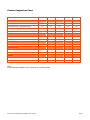
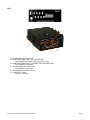
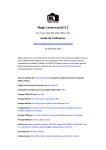
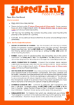
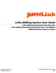
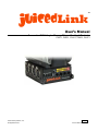
TM
juicedLink
User’s Manual
Camcorder XLR Adapter/Preamp/Mixer - Family of Products
CX211, CX231, CX411, CX431, CX471
© 2007-2009 juicedLink, LLC.
All Rights Reserved.
ENGLISH
CX User Manual: Rev1.02
Contents
Contents.......................................................................................................................................2
Read This First .............................................................................................................................3
Warnings - General ...................................................................................................................3
Checking Supplied Items .........................................................................................................3
General.........................................................................................................................................4
Features....................................................................................................................................4
Optional Features .....................................................................................................................4
Feature Comparison Chart .......................................................................................................5
Panel Descriptions ...................................................................................................................6
Input Connection..........................................................................................................................9
Unused XLR Inputs ...................................................................................................................9
Input Attenuator (MIC/LINE).....................................................................................................9
Phantom Powering Condenser Microphones ...........................................................................9
Use with Unbalanced Sources (Wireless Mics, Etc)..............................................................10
Output Connection .....................................................................................................................12
Output Signal..........................................................................................................................12
Connection to Camcorder ......................................................................................................12
Connection to Recorders, Computers, etc.............................................................................12
Audio Settings............................................................................................................................13
General Principles and Guidelines .........................................................................................13
Selecting Mixer Preamp Gain.................................................................................................13
Adjusting Trim ........................................................................................................................13
Metering..................................................................................................................................14
Mixing (Pan Switch)................................................................................................................14
High-Pass Filter ......................................................................................................................14
Power .........................................................................................................................................15
Power Sequence.....................................................................................................................15
Rechargeable Batteries .........................................................................................................15
Mounting ....................................................................................................................................16
Positioned Under Camcorder .................................................................................................16
Rotation Secured with Azimuth Pin ...........................................................................................................16
Rotated Position – Unsecured ..................................................................................................................16
Mounted to Tripod ..................................................................................................................16
Other Positions – Shoulder Strap ...........................................................................................16
Appendix ....................................................................................................................................17
Care and Maintenance ...........................................................................................................17
Warranty, Service, and Returns .............................................................................................17
Compliance.............................................................................................................................17
Page 2
www.juicedLink.com
Read This First
Before operating the unit, please read this manual thoroughly.
Although there are numerous combinations of settings for the mixer gain plus recording device gain (camcorder)
that will result in the identical signal levels, they will have different characteristics in terms of noise and dynamic
range. This manual provides guidelines and practices to yield the best overall signal purity.
Any future revisions will be posted on the website and available for download.
Some of the features described in various sections may not be available on your model. Please refer to the
Feature Comparison Chart to determine the capabilities of your particular device.
Notes regarding documentation in this manual are as follows:
- References to markings/labels on the unit are denoted in underline/bold. For example: HPF.
- Warnings will be preceded with WARNING.
Warnings - General
WARNING: Failure to read and observe notes and warnings may result in personal injury, and/or possible damage
to this device and your other equipment.
WARNING - LOSS OF HEARING: Although headphones do not plug directly into this mixer, it is common for
headphones to be used with other equipment to monitor the audio signal transmitted by the mixer. The devices
that are driving the headphones, such as camcorders, are often capable of driving the signal at levels that can be
damaging to hearing. Always operate the headphone volume at the lowest practical level. Do not wear the
headphones over your ears in any of the following circumstances:
- While plugging the headphones into the headphone driving device.
- While plugging the mixer into the headphone driving device.
- While turning on or off the mixer.
- While turning on or off the phantom power.
- While plugging a device into the input of the mixer.
WARNING - RISK OF ELECTRICAL SHOCK: This device, its enclosure, and the connections to cable shields that
plug into this device are conductive. Avoid electrocution and observe caution with cable runs near areas where
high-voltages and/or currents may exist.
Checking Supplied Items
Your package should include the following items:
- Ultra-Portable Mixer model that you purchased.
- 9-inch cable with stereo male 3.5mm plugs on each end.
- 1/8 inch hex key
- Quick Start Guide
Camcorder XLR Adapter/Preamp/Mixer User’s Manual
Page 3
General
Some of the features described in this and other sections may not be available on your model. Please refer to
the Feature Comparison Chart to determine the capabilities of your particular device.
Features
•
•
•
•
•
•
•
Family of 2 and 4 input Camcorder XLR Adapter/Preamp/Mixers
Inputs
o Precision laser-trimmed active balanced inputs for use with professional mics
o Un-balanced capable (e.g. wireless mic receivers) - connect pin 1 to pin 3
o Low-noise preamplifier, 3 adjustable gain settings
o Line level signal input attenuator switch (first 2 channels)
Output
o 3.5mm stereo jack
o Amplified Mic Level
o Driver protection from external DC voltages generated by some camcorders
True channel mixer, with L/C/R pan switches
Frequency response of +/- 1dB max from 20Hz-20KHz
Low battery indicator
Construction
o Aluminum chassis (black anodized) for EMI protection and rugged use
o Flexibility to mount under camcorder, on top of tripod, small enough to use with camcorder hand
strap, facilities for connection to shoulder strap (shoulder strap not included)
Optional Features
•
•
•
•
Page 4
High Pass Filters (low-cut filters), reduces audible rumble from wind
Audio Level Metering - 10 segment LED per R/L - Adjustable
48V phantom power
Power saving 12V phantom
www.juicedLink.com
Feature Comparison Chart
Features
CX211
CX231
CX411
CX431
CX471
2
2
4
4
4
Low noise preamp - High/Med/Low gain
yes
yes
yes
yes
yes
Precision active input balance
yes
yes
yes
yes
yes
Line level switch
yes
yes
yes1
yes1
yes1
yes
yes
yes
yes
yes
-
-
-
-
yes
yes
yes
yes
yes
yes
48V Phantom
-
yes
-
yes
yes
12V Phantom power saving mode
-
yes
-
yes
yes
yes
yes
yes
yes
yes
-
-
-
-
yes
Inputs
XLR input channels
Signal Processing
True Mixer - per channel L/R/C pan switch
Per channel low-cut filter
Outputs
3.5mm stereo
Phantom Powering
Indicators
Low Battery Indicator
Audio Level Meter - 10 segment LED L/R
Notes:
1) Line switches available for first 2 channels on 4 channel mixers.
Camcorder XLR Adapter/Preamp/Mixer User’s Manual
Page 5
Panel Descriptions
FRONT
10
9
6
8
2
1
11
5
7
11
1)
2)
3)
4)
5)
6)
7)
8)
9)
10)
11)
Page 6
3
4
POWER SWITCH
“ON” LED INDICATOR
LOW BATTERY INDICATOR
PREAMPLIFIER GAIN SETTINGS
TRIM POTENTIOMETERS
AUDIO METER DISPLAY (RIGHT/LEFT)
Not available on all models.
AUDIO METER POWER SWITCH
Not available on all models.
XLR INPUTS
UNDER-CAMERA ATTACH SCREW
AZIMUTH PIN (removable)
SHOULDER STRAP CONNECTION POINTS
Shoulder strap not included.
www.juicedLink.com
REAR
3
6
2
1
4
5
1) STEREO MIC LEVEL OUTPUT
2) PHANTOM POWER “ON” / VOLTAGE SELECT
Not available on all models offering phantom power.
3) PHANTOM POWER INPUT CHANNEL ROUTING SWITCHES
Not available on all models.
4) PER CHANNEL HPF SWITCHES
Not available on all models.
5) PER CHANNEL PAN SWITCHES
6) 9V BATTERY TRAY
Battery not included.
Camcorder XLR Adapter/Preamp/Mixer User’s Manual
Page 7
BOTTOM
5
4
3
2
1
1) TRIPOD MOUNT
2) AZIUMUTH HOLE
3) UNDER-CAMERA ATTACH SCREW:
1/8” hex key included.
4) AUDIO METER ADJUST (R/L)
Not available on all models.
5) INPUT ATTENUATOR (MIC/LINE) SWITCH
Note: The bottom of the unit is silk-screened with handy tips and instructions.
INCLUDED
1
2
1) SHIELDED STEREO MINIJACK OUTPUT CABLE
2) TRIPOD SCREW ALLEN WRENCH KEY
Page 8
www.juicedLink.com
Input Connection
Some of the features described in this and other sections may not be available on your model. Please refer to
the Comparison Chart to determine the capabilities of your particular device.
Unused XLR Inputs
When a preamp does not have an input connected to it, the preamp is presented with a high impedance. When a
preamp is presented with a high impedance, it will produce a lot of noise. So, for any XLR input channel that does
not have an input connected to it, make sure to turn the corresponding TRIM down all of the way.
Input Attenuator (MIC/LINE)
Channels 1/2 have a 40dB input attenuator switch on the bottom of the unit that can be engaged to protect the input
preamp from overloading in the presence of high signal levels. If connecting line level signals to the input of either
channel 1 or 2, then set the corresponding attenuator switch to LINE. Similarly, if connecting microphone level
signals, then set the attenuator switch to MIC.
Channels 3/4 in 4 channel mixers are not equipped with input attenuators. They are to be used with microphone
level signals, similar to the MIC setting.
The 3.5mm output plug connections from the receivers of wireless microphone systems can be treated as
microphone level signals. It is reasonable to assume that if the output from a product was intended to go into the
microphone input of the camcorder, then the MIC setting on the mixer should be used.
Phantom Powering Condenser Microphones
12/48V phantom power is not available on all models.
Condenser microphones require a voltage for operation. Some microphones have facilities for an internal battery.
Other microphones need to be operated from phantom power, which is when the voltage is generated by the device
that the microphone cable plugs into on the other end from the mic, and the voltage is transmitted up the
microphone cable.
There are some advantages to phantom powering mics. On some mics, their specs are improved when operating
from phantom power instead of the internal battery. Microphones that operate from phantom only tend to be
shorter and lighter (since they don’t have a battery or battery compartment), so they are easier to boom (remember,
you should be getting the mic off of your camcorder and booming frequently to get the mic closer to the source for
the best microphone placement).
The internal switching power supply generating the will generate a phantom voltage corresponding to the switch
12V and 48V switch positions. When phantom power is not in use, then leave the internal switching power supply
in the OFF position to conserve battery life.
Once the switching power supply voltage has been selected and is being generated by the internal switching power
supply, power can be supplied to the individual channels. This is accomplished by setting the Phantom channel
switches (1, 2, etc.) to the On position. Then, the phantom voltage is supplied to pins 2 and 3 on the activated
channels through current limiting resistors.
Many older condenser microphones will operate from 48V only. The phantom voltage should be set to 48V if any of
your microphones require 48V.
However, there are many modern condenser microphones which are specified for 11-52V operation. If all of you’re
the condenser microphones being used can operate down to 12V, then use the 12V setting for the phantom
voltage. This will significantly increase battery life, since the switching power supply will not have to work as hard
to boost the voltage from 9V to 12V (compared to boosting it to 48V).
Camcorder XLR Adapter/Preamp/Mixer User’s Manual
Page 9
WARNING – HIGH DC VOLTAGES CAN POTENTIALLY DAMAGE OUTPUT DRIVERS ON ELECTRONIC
EQUIPMENT. Use care, heed warnings, and follow guidelines when using phantom power.
WARNING – USE PHANTOM POWER FOR CONDENSER MICROPHONE INPUTS ONLY: Only activate
phantom power to channels using condenser microphones. Supplying phantom power to dynamic microphones is
not a recommended practice, even though there is no voltage potential between pins 2 and 3 and theoretically
should not cause damage. Supplying phantom power to other types of electronic equipment, whether balanced or
unbalanced, can potentially damage their output drivers.
Use the following best practice procedure for phantom powering:
1) Connect only a condenser microphone to the desired mixer input.
2) If all of the channels requiring phantom power are using condenser microphones that allow for the use of
12V, then set the voltage selector switch to 12V.
3) If any of the channels needing phantom power are using a condenser microphone requiring 48V, then set
the voltage selector switch to 48V.
4) After all of the desired condenser microphones are plugged in, then set corresponding the Phantom
channel switches to the On position.
5) After use is complete, turn off all of the Phantom channel switches before removing the condenser
microphones, and turn the phantom power supply to OFF.
6) Unplug the condenser microphone.
Use with Unbalanced Sources (Wireless Mics, Etc)
XLR inputs have 3 pins (3 connections for a single audio signal). Pin 1 is for ground. The audio signal in present
on pins 2 and 3, and is what is know as a “balanced” signal. That is to say that the signal on one wire is identical
but opposite in polarity to the other (pin 2 is known as “hot” or the positive polarity). Balanced signals when
terminated properly (as in the juicedLink) have a high immunity to picking up noise and interference. This is
especially important for microphone level signals and cable runs longer than a few feet.
There are times when you will want to interface to unbalanced signals. This is where a single audio signal is
reference to ground (only 2 connections for a single audio signal). For example, many wireless receivers output a
unbalanced signal.
The juicedLink XLR inputs can interface with unbalanced sources. To do this, a simple modification to the
cable/plug that will be inserted into the mixer input is required. Connect pins 1 and 3 together for the signal ground.
Pin 2 remains as the input signal.
So, for a wireless receiver that uses a 3.5mm plug for its output, the audio signal will be on the “tip”, and the ground
will be on the “sleeve”. The plug “sleeve” needs to be connected to XLR pins 1 and 3, and the plug “tip” needs to
be connected to XLR pin 2.
Fortunately, many wireless kits (such as the Sennheiser G2) come with a minijack to XLR cable which already
makes this connection.
For those kits which do not come with the appropriate cable, you will need to use some inexpensive adapters.
One inexpensive handy adapter is the Rode VXLR. However, you will need to be careful. The VXLR makes a
connection between the minijack “sleeve” and “ring”. For a miniplug which has a “tip”, “ring”, and “sleeve”, this is
not a problem. But, on some inexpensive wireless kits (from Azden), the output miniplug connects the “ring” and
“sleeve” together. So, the VXLR is not usable for such plugs.
Here are some other inexpensive adapters which are handy for connection to unbalanced sighals:
XLR(M) to 3.5mm(F): Rode VXLR (be careful … see above)
XLR(M) to RCA(F): Hosa GXM133
RCA(M) to 3.5mm(F): Comprehensive PP-MJ
Stereo 3.5mm(F) to two mono right/left RCA(M): Hosa YMR-197
Page 10
www.juicedLink.com
WARNING – DO NOT ACTIVATE PHANTOM POWER ON XLR INPUT CHANNELS CONNECTED TO
UNBALANCED DEVICES. The voltage from the phantom power can damage these devices. See the warnings in
the Phantom Powering Condenser Microphones section of this manual.
Camcorder XLR Adapter/Preamp/Mixer User’s Manual
Page 11
Output Connection
Output Signal
The output of the juicedLink is an amplified mic level signal. The juicedLink is not intended to drive line level
signals. It is not necessary to have a lot of gain to interface with a camcorder. You want just enough gain to be
able to throttle back the noisy camcorder amplifiers, to yield improved signal-to-noise performance while recording
fine audio detail. To much gain would overload the camcorder.
Connection to Camcorder
Connect the plug from one end of the shielded cable to the OUT 3.5mm stereo jack on the mixer. Connect the plug
from the other end of the cable to the camcorder’s microphone input jack. The camcorder’s integrated microphone
will now be disabled.
Some camcorder microphone input jacks supply low voltage DC for powering external microphones. Therefore, the
mixer output driver has been protected from external voltages with DC blocking capacitors. Large capacitance
values have been selected to provide excellent low frequency response.
Connection to Recorders, Computers, etc.
The output of the juicedLink can be connected to any recording device expecting stereo minijack mic level signals.
Page 12
www.juicedLink.com
Audio Settings
General Principles and Guidelines
HEADPHONE MONITORING: To be certain that your camcorder and mixer settings are optimized for the signal
being recorded, it is a best practice to monitor the audio using headphones driven by the camcorder. A meter may
indicate if there is sufficient signal. However, a meter gives you no indication of signal-to-noise. The signal level
may be fine, but the audio could still sound poor. This could be because of noise (background, echo, failing mic)
that you would not realize is present. So, it is a best practice to always monitor with headphones. Follow hearing
safety guidelines in the Warnings section of this manual.
DISTRIBUTION OF CAMCORDER/MIXER GAIN: There are numerous combinations of gain settings between the
camcorder and mixer that will result in identical signal levels. However, each combination has unique properties in
terms of noise and dynamic range. The mixer preamp is, in general, a lower noise device than the front end of
most camcorders. Better signal purity will result with the camcorder set to a low gain level, and let the juicedLink
low-noise preamps do the heavy lifting for the gain. This is controlled via various methods for different camcorders.
Higher-end camcorders will have a switch to turn off the ACG, then potentiometers to control the gain. Having the
potentiometers adjusted to approximately 1/3 level is a reasonable starting point. Some camcorders (such as many
of the Sony HDR series) may have a LOW setting. Although this does not turn the AGC off, it sets it at a much
lower level (injecting less noise).
CAMCORDER AGC: Automatic Gain Control (AGC) is circuitry that increases the gain for low signals, then cuts
back the gain for large signals. This is helpful to even out the audio for near/far sources, and prevent overloading
of the recording circuitry. There are definitely environments where AGC is called for, especially where signal levels
can vary greatly and be unpredictable. We chose not to implement a separate limiter in the mixer, since you have
the option to use AGC in your camcorder (and the limiter would add noise and burn current). The downside of the
AGC circuitry is that it always searches for some signal to amplify. During periods of low audio signal levels, the
AGC will start amplifying the ambient noise in the room, or other unwanted noise. If your environment’s signal
levels are generally constrained or more predictable, then the recorded audio quality will improve greatly by turning
the AGC off.
UNPREDICTABLE SIGNAL LEVEL ENVIRONMENTS: In unpredictable signal level environments (say, a kids
birthday party), the wide dynamic range and overload protection of the camcorder’s AGC circuitry.
RECORDING FINE AUDIO DETAIL: It is desirable to get the best noise performance from your equipment while
recording fine audio detail, such as dialogue. In these cases, set your camcorder to manual and throttle back the
gain to roughly 1/3 the level. Then, turn up the trim on the juicedLink’s low-noise preamps. This turns down the
camcorder’s noisy amps, and replaces it with the clean gain from the juicedLink.
Selecting Mixer Preamp Gain
Read the Input Attenuator section for instructions on selecting the appropriate attenuator position.
There are 3 preamp gain settings (HIGH, MED, and LOW). Having a number of gain settings to choose from
allows for an optimal adjustment range of the TRIM control. With microphone inputs during normal use, you will
find that you will be mostly on the HIGH setting. The MED and LOW settings will mostly come into play if you are
using extremely sensitive mics in very high SPL environments.
Adjusting Trim
On unused XLR input channels, turn down the TRIM all of the way. This removes the possibility of unused
channels adding noise to the output signal. Each channel is buffered, so this can be done without adversely
loading or effecting adjacent channel signal-to-noise ratio (unlike many passive adapters).
Read the previous sections DISTRIBUTION OF CAMCORDER/MIXER GAIN and CAMCORDER AGC for an
understanding of the principles and guidelines for the camcorder and mixer gain settings.
Camcorder XLR Adapter/Preamp/Mixer User’s Manual
Page 13
Monitor using headphones and adjust the TRIM potentiometers to achieve the desired relative signal level between
the various channels used.
Metering
The audio meter feature is not available on all models.
First, the meter will need to be calibrated to your camcorder’s settings. Once calibrated, changing camcorder
settings will result in the meter being uncalibrated. Calibration can be performed to correlate with an existing meter
on the camcorder. Calibration can also be setup empirically by speaking a constant level tone into a microphone,
increasing the gain until clipping internal to the camcorder, then backing off the gain to a safe level, then adjusting
the meter to the 0dB reference.
The meter is adjusted by using a small screw with the Meter adjust right and left potentiometers.
Mixing (Pan Switch)
This device is a true channel mixer, providing independent signal routing control for each input channel via the PAN
switches. L routes the input signal for the corresponding channel (1 through 4 for 4 channel mixers) to the left mix
bus. R routes the input signal for the corresponding channel to the right mix bus. C routes the input signal for the
corresponding channel equally to both the left and right mix buses.
High-Pass Filter
The high-pass filter feature is not available on all models.
High-pass filters, also known as low-cut filters, are used to reduce excess low frequency energy from the audio
signal. An instance where this is useful is when low frequency rumble results from wind rushing across the
microphone. The design is to have the -3dB point centered at 180Hz, with a rolloff of -6dB/octave.
To engage the high-pass filter, slide the HPF switch for the corresponding input channel (1, 2, etc) to the On
position.
Page 14
www.juicedLink.com
Power
Power Sequence
-
Place an alkaline 9V battery in the tray. Make certain to use the correct orientation.
Turn on the power by sliding the PWR switch to the On position.
The “ON” LED will now be illuminated.
Turn off the power when not in use to conserve the battery.
The low battery indicator LED (Low Batt) will illuminate when the battery supply needs to be changed. The
threshold has been preset for use with alkaline 9V batteries.
Rechargeable Batteries
It is not recommended to use the unit with rechargeable batteries. The low battery indicator has been calibrated for
use with alkaline 9V batteries. Other battery types will not illuminate the low battery indicator the appropriate
voltage for that type of battery.
Camcorder XLR Adapter/Preamp/Mixer User’s Manual
Page 15
Mounting
Positioned Under Camcorder
Rotation Secured with Azimuth Pin
Align the azimuth pin and mounting screw on top of the mixer, with the corresponding holes on the bottom of the
camcorder. Use the 1/8” hex key (provided) to tighten the mounting screw. Check to make sure that the
connection is tight enough, and the azimuth pin is constraining rotation between the two.
Rotated Position – Unsecured
There may be circumstances where you wish to have the XLR connectors and cables protruding from your setup in
a different orientation from the one secured from the azimuth pin. The azimuth pin may be removed, providing
freedom of rotation. Only use this configuration while you are shooting and holding the camcorder itself with your
hands.
WARNING - PHYSICAL DAMAGE TO YOUR EQUIPMENT SET MAY RESULT IF YOU USE THE TRIPOD
MOUNT ON THE BOTTOM OF THE MIXER TO SECURE YOUR EQUIPMENT SET, AND THE CAMERA IS
MOUNTED TO THE MIXER WITHOUT SECURING THE ROTATION BY USING THE AZIMUTH PIN.
Mounted to Tripod
First, follow the directions to mount the camera to the top of the mixer. Make sure that the rotation is secured with
the azimuth pin.
Next, align the azimuth pin and screw from the tripod head with the holes on the bottom of the mixer, and tighten.
Make sure that the rotation at this point is also secured by the tripod head azimuth pin.
WARNING - PHYSICAL DAMAGE TO YOUR EQUIPMENT SET MAY RESULT IF YOU USE THE TRIPOD
MOUNT ON THE BOTTOM OF THE MIXER TO SECURE YOUR EQUIPMENT SET, AND THE CAMERA IS
MOUNTED TO THE MIXER WITHOUT SECURING THE ROTATION BY USING THE AZIMUTH PIN.
Other Positions – Shoulder Strap
The aluminum enclosure has the facilities for other methods of attachment, for example, a shoulder strap. If the
strap attachments are too large to fit in the holes, then attach a key-ring like device to make attachment holes large
enough.
Use of a shoulder strap is preferred to use of a belt clip. With a belt clip, you will have heavy microphone wires
tugging at your belt. You don’t want to be distracted and miss the shot because you were pulling up your pants.
We have not included a shoulder strap in the package. More customers are mounting to the camera. Also,
customers that do want to use a shoulder strap are particular about length and width, etc.
Page 16
www.juicedLink.com
Appendix
Care and Maintenance
Store the mixer without battery in tray to avoid damage from a chemistry leak event.
There is no specific maintenance regimen recommended.
Warranty, Service, and Returns
The design of the juicedLink family of ultra portable mixers is uncompromising in quality and performance, and
utilizes top grade professional components. We are proud of our product, and are committed to servicing you to
make your customer experience positive.
The Policies page on the juicedLink.com website describes the details of the conditions for returns, limited one year
warranty, and instructions for obtaining service for your product.
Compliance
This device falls under the classification of FCC part 15, subpart B, section 15.103. Please refer to the FCC part 15
manual for details on conditions of operation.
This device has also been tested to meet CE certification standards.
Camcorder XLR Adapter/Preamp/Mixer User’s Manual
Page 17