1
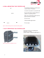
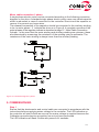
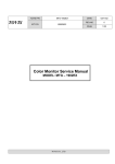
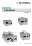
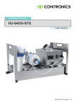
USER MANUAL CoMoCo-1.0-ED-4
03-06-2014 version 1.6
CE DECLARATION OF CONFORMITY
CoMoCo B.V., Ambachtsweg 8, 5492 NJ Sint-Oedenrode, The Netherlands, declares that
this intelligent motor controller, CoMoCo-1.0-ED-4, has been produced in accordance with
the CE guidelines included in the standards below.
It must be installed according to the accompanying instructions.
The intelligent motor controller must not be put into operation before the installation
complies with the CE guidelines.
EMC guideline : 2004/108/EC
Low voltage guideline : 2006/95/EC
2
Table of content
1. PREFACE��������������������������������������������������������������������������������������������������������� 4
2. Explanation of pictograms������������������������������������������������������������� 5
3. PRECAUTIONARY MEASURES������������������������������������������������������������������ 5
4. SCOPE OF DELIVERY���������������������������������������������������������������������������������� 6
5. CIRCUIT DIAGRAM FOR CONTROLLER������������������������������������������������� 7
6. WALL-mounting THE CONTROLLER���������������������������������������������������� 8
7. DUCT mounting the controller ��������������������������������������������������� 8
8. CONNeCTIONS���������������������������������������������������������������������������������������������� 9
9. COMMISSIONING����������������������������������������������������������������������������������������� 13
10. LED indication���������������������������������������������������������������������������������������� 14
11. Technical information�������������������������������������������������������������������� 15
12. Maintenance������������������������������������������������������������������������������������������ 15
3
1. PREFACE
General
This manual contains the operating and installation instructions for the intelligent motor
controller, type CoMoCo-1.0-ED-4.
CoMoCo-1.0-ED-4 is an intelligent controller for electromotors. At the heart of the controller is the Texas Instruments C2000 Piccolo microcontroller. The controller measures the
electromagnetic field in the electromotor without using mechanical sensors. The built-in
software accurately estimates where the magnetic field will be in the next microsecond.
It calculates the minimum and the type of energy required to realise this field and then
precisely supplies it, using the data obtained. The result is enormous energy savings in
partial load.
Depending on the type of electromotor and the required capacity, up to 90% more
energy can be saved in respect to a controller based on Triac. The highest percentage
of energy saving occurs when the rotational speed is low. The required rotational speed
is controlled by a 0-10Volt or 10-0Volt signal. The rotational speed is guaranteed by the
controller, irrespective of external influences.
The controller also ensures that the required rotational speed can be maintained with
the absolute minimum of energy. The controller supplies this energy in an optimal form
in regard to voltage, current and frequency.
PFC
CoMoCo-1.0-ED-4 fully complies with the CE guidelines. Extra EMC filters are not
necessary when installing.
A built-in PFC (Power Factor Control) ensures that the energy is taken evenly from the
public grid and is available when required. The controller performs far above the standard
set by the energy companies. In addition the PFC is dynamic. In other words it switches
off when the load is low to save even more energy.
Input, output and power
The input voltage is between 85 and 265Volt (50-60Hz), both for 1- phase and 3-phase
electromotors.
The output signal is suitable for a three phase 230 – 380V induction motor which is delta
connected or a single phase induction electric motor 230V where the capacitor of the
auxiliary winding is disconnected.
The controller can supply 1,000VA of power with static cooling and when the controller
is placed in an air flow up to 1,150VA. The abovementioned applies for a supply voltage
of 230VAC.
The controller will operate at a lower voltage, but will automatically reduce the maximum
power that can be supplied. The controller will supply a maximum of 500VA at 110VAC.
4
Extra intelligence
When overloaded the controller will remain working by reducing the supplied power.
The controller can run the electromotor at a much lower rotational speed than is usual
possible with the current available controllers. Moreover up to 150% of the maximum
torque is available at these low rotational speeds and at idle without damaging the
motor. In the event of an overload or the temperature is too high or other malfunctions
the controller will continue to operate but will also produce an alarm signal via
a potential-free contact. The cause of the alarm can be read from a flashing LED signal
underneath the controller.
The housing is extremely robust and completely enclosed so that the controller can
also be placed in aggressive surroundings.
The direction of rotation of the connected electromotor can be set by the control cable.
Installation
For proper functioning and to conform to the CE rules, the controller must be installed
no further than 2.5 metres from the electromotor. The electronics are enclosed in an
aluminium housing with a special coating suitable for aggressive surroundings. The
housing conforms to the IP67 standard. The required cables have been pre-installed to
guarantee IP67 and CE. Opening the controller is therefore unnecessary. Opening will
be detected and the guarantee will be void.
It is imperative for optimal working that the motor is recognised and the controller
calibrated when connected. This is easy to start up by briefly connecting two of the
wires in the control cable to each other.
The procedure will then run fully automatically. The electromotor must be able to move
freely. After a short while the controller and motor will be tuned to each other.
2. Explanation of pictograms
Danger! Risk of electric shock or danger if the following
instructions are not observed.
Warning
Read the following text carefully because it contains
important information. The working of the controller
cannot be guaranteed if this is not taken into account.
Important
Following text contains especially important information.
5
3. PRECAUTIONARY MEASURES
Read the following instructions carefully before connecting or starting up the controller.
Breakdowns and injury could result if the instructions in this manual are not followed.
The manufacturer retains the right to change the specifications of the controller and its
performance or the contents of this manual without giving prior notification.
Although
mend
for the
the controller is protected from overload and overvoltage, we recomthe installation of an additional safety device on the supply circuit
alarm system.
The
connecting cables are fed through waterproof glands on account of
the IP67
standard.
Do NOT drill extra holes in the housing because this will result in the controller no longer
meeting the IP67 standard.
IMPORTANT
Opening will be detected and the guarantee will be void!
4. SCOPE OF DELIVERY
The controller packaging must include the following items:
CoMoCo-1.0-ED-4
Manual
6
5. CIRCUIT DIAGRAM FOR CONTROLLER
Electromotor
▶1-phase
▶3-phase
Controller
3x230V
1
2
3
▶
U
V
W
Earth
Shielding
Max. 2.5 metres
Supply 85 - 265V AC
N
L
Earth
LED
Status
Max. 300 metres
Ground <-- Green
Blue --> +10V *
Control device
Control voltage (0 - 10V / 10 -0V) <-- White
Yellow --> Calibration / motor recognition
Brown -->
Grey-->
}
Potential free / Alarm contact (NO)
Pink --> Inverting control voltage
Red --> Inverting direction of rotation
* Protected by heat-shrink tubing to prevent supply voltage
short circuiting
Figure 1. Connections.
7
6. WALL-mounting THE CONTROLLER
- The distance between controller and
motor is max. 2.5 metres.
- It must be mounted on a smooth wall.
242mm
- Do not mount the controller above a
radiator or anything similar
- Take care of adequate space and air
flow around the controller.
- Do not cover.
- Cable feedthrough bottom.
107mm
- Do not open.
Figure 2. Wall-mounting of the controller with drilling pattern
7. DUCT mounting the controller
Optional brackets for installing the
controller on a duct.
(order number: COMOCO-BRACKET-1)
Figure 3. Brackets for installation on duct.
8
8. CONNeCTIONS
General guidelines for the electric installation and safety
•
All work in to the installation, commissioning, remedying breakdowns
and maintenance must be implemented by qualified electro-technical personnel
(observe EN 50110, EN1010, IEC 60364, IEC 60204 and the national safety
precautions therein).
The mains supply must be switched off during installation and repair work.
The controller contains parts that are subject to high voltage when connected
to the mains supply. Incorrect connection of the controller could cause damage
and physical injury or have fatal consequences. Follow the instructions in this
manual, as well as the local and national safety precautions.
IMPORTANT: Motor is delta connected in case of a 3-phase control (output
voltage is 3x230V).
Contact with electrical parts could lead to serious physical injury or death even
when the mains supply is switched off. Wait for 5 minutes after the mains supply
has been switched off before starting work.
•
The user or installer is responsible for correct earthing and protection in accordance
with the applicable local, national and international regulations.
•
The voltage supply to the controller unit must have a series fuse. See the
maximum voltage use in the table of technical data (chapter 11)for the control unit
for the correct value.
•
The earth leakage protection on the control unit amounts to more than 3.5 mA (AC).
According to the EN61800-5-1 standard, the required safety circuit must conform
with one or more of the following conditions:
- A second earth wire with the same cross section as the original earth
wire connected to an extra terminal clamp.
- Or the earth wire must have a cross section of at least 10 mm2 Cu or
16 mm2 Al along the whole connection.
- Or a provision for the automatic interruption of the power supply in
the case the earth wire being interrupted.
•
The controller could cause a direct current in the earth wire.
If a circuit breaker is used in the case of direct or indirect contact protection,
a circuit breaker type B must be used in the supply wire to the control unit.
9
General guidelines for installing the controller
The method of installing the wiring and the accompanying components is important for
proper working and compliance to the applicable regulations when using the controller.
A number of important points for attention:
•
Motor cable may not be extended.
•
Connect the motor directly to the controller. Make sure there are as few as
possible junctions in the cable (i.e. terminals) between controller and motor.
•
Strip the motor cables as short as possible and connect the shieliding to earth
on 2 sides.
•
Do not put the cable between the controller and the motor in the same cable
duct as the supply cables, control voltage cables and signal cables.
•
All signal cables must be as close to each other as possible and of course as far
as possible from the cable between controller and motor.
•
Two-sided earthing is imperative for shielding from the low frequency interference voltage.
•
Do not run signal cables and cables parallel between controller and motor,
keep a distance of at least a half metre and keep crossover points at an angle of 90°.
•
If the earth shield on the cable between controller and motor has to be interrupted,
install the earth shield with a reliable terminal (EMC) on a wide flat
conductor. A reliable (EMC) terminal clamps the shield as completely as possible
and makes a connection with an impedance for high frequency signals that is as
low as possible.
•
Safety earth and earthing for suppression may be combined, however the earth
connection for suppression must have an impedance that is as low as possible.
Therefore no long wires but as short as possible and a strip or board that is as
wide and flat as possible.
Control cable
Various functions of the intelligent motor controller can be adjusted via the control cable:
- Adjustment of the rotational speed by means of a control voltage (0-10V or 10-0V)
- Starting calibration
- Alarm output (potential free); Normally Open (NO)
- Inverting control voltage (10 - 0V)
- Inverting direction of rotation
An overview of the control cable wires can be found in the table below.
Control cable
connection colours
Description
Green
Ground
Blue
10V max. 10mA
White
Control voltage (0 -10V / 10 - 0V)
Yellow
calibration / motor recognition
Brown
Grey
Potential free / Alarm contact (NO)
Pink
Inverting control voltage
Red
Inverting direction of rotation
10
Figure 4. Control cable
wires.
IMPORTANT: The controller can suffer irreparable damage if the control
cable wires unintentionally short-circuit.
Adjustment of rotational speed by means of external control voltage
The rotational speed of the electromotor can be adjusted by means of a control voltage
from external control equipment. The control voltage for this controller must be connected
as shown in figure 5.
Figure 5. Adjustment by means of external voltage.
In most cases the external control equipment will supply a control voltage of 0-10V at
the minimum and maximum rotational speed percentage respectively. The controller will
work inverted if this control voltage amounts to 10-0V in the same situation. If the control
voltage cannot be inverted via the external control equipment it will be necessary to
adjust this inversion on the controller. This inversion can be adjusted by connecting the
pink wire (inverting control voltage) and the green wire (ground) of the control cable to
each other.
Adjustment of the rotational speed by means of variable resistance (potentiometer)
The rotational speed of the electromotor can be adjusted by means of a variable
resistance which must be connected according to figure 6.
The variable resistance value must be 10kOhm linear.
Figure 6. Adjustment by means of variable resistance.
Set direction of rotation
The direction of rotation can be adjusted by connecting the red wire (invert the direction
of rotation) and green wire (ground) of the control cable to each other.
IMPORTANT: The 10V wire may only be used to create a control voltage
by means of a variable resistance (potentiometer) as shown in figure 6.
Protected ex-factory in heat-shrink tubing to prevent the supply voltage
from short circuiting.
11
Supply cable connection
The controller is supplied with mains voltage by the supply cable.
It is advisable to connect the motor and control cable prior to connecting the
supply cable. An overview of the connections of the supply cable can be found in the
table below.
Supply cable
connection
colours
Description
Brown
Phase (L)
Blue
Null (N)
Yellow / green
Earth
Figure 7. Supply
cable wires.
Motor cable connection 3-phase
The motor cable connects the electromotor to the controller. The wires in this cable are
numbered and correspond to the three motor phases shown in figure 8. The direction of
rotation must be checked if the motor connections (U, V, W) are not known.
Any 2 phases must be swapped if it does not rotate in the required direction. An overview of
the connections of the motor cable can be found in the table below.
Motor cable
Description
1
Motor phase U
2
Motor phase V
3
Motor phase W
Yellow / green
Earth
Shielding
Earth
Figure 8. Motor
cable wires.
Earth connection
Shielding
Phase connection
Figure 8. Connections 3-phase.
12
Motor cable connection 1-phase
A single phase electric motor can be connected according to the following connection
diagram on the drive. A standard single phase electric motor uses a so-called capacitor
which is redundant in case of connection to the controller. Short-circuit the capacitor or
remove it to prevent any loose wires.
The released connection of the capacitor should be connected to the auxiliary winding,
to be, to motor phase ‘ 2 ‘ indicate the drive as in Figure 9. A complete overview of the
motor phases of the regulator indicate is described at page 12 ‘ Motor Cable Connection
3-phase ‘. In the event that the main winding and auxiliary winding are unknown, these
are determined by measuring the resistance of the winding using a multimeter. The
resistance of the main winding is always lower than the auxiliary winding.
Figure 9. Connection diagram 1-phase.
9. COMMISSIONING
Step 1
Ensure that the electromotor and control cable are connected in accordance with the
instructions before supplying mains voltage to the controller. The LED indication on
the controller will start to flash as soon as the mains voltage is supplied because the
Calibration procedure/motor recognition has not yet been performed.
The LED indication will flash 5 times with pauses of 4 seconds.
13
Step 2
The Calibration can now be started by connecting the green (ground) and the
yellow (calibration) wires in the control cable together for 3 seconds. Make sure that the
electromotor can rotate freely. The LED indication will flash green afterwards and the
electromotor will make a number of rotations. The calibration is complete as soon as the
LED indication lights up green continuously. For 3-phase this is approximately 2 minutes
and for 1-phase this is approximately 5 minutes.
Step 3
The controller is now ready for use and the rotational speed of the electromotor can be
adjusted using the control voltage. Check the electromotor for correct rotational direction.
If the rotational direction differs from what is expected, check the motor connection or
check red wire of the control cable as described in chapter 8.
IMPORTANT: The whole commissioning procedure must always be
repeated when re-using the controller or replacement of the motor.
In that case the red LED will in fact not flash 5 times because all the
motor parameters are known from the previous motor.
A new calibration is necessary.
10. LED indication
LED description
Indication
Continuous green
Normal operation
Flashes green
Calibration
Continuous red
During swtiching
Alarm
Cause
Solution
DC link precharging
During switching
DC link discharging
Flashes 1 x red with
pause of 4 sec.
PFC overflow
●
PFC flow too high
Check quality of the mains
voltage and motor status
Flashes 2 x red with
pause of 4 sec.
Motor overflow*
●
Motor flow too high
Check wiring and motor
status
Flashes 3 x red with
pause of 4 sec.
Overtemperature
●
Overload.
Controller temp. or
ambient temp. too high
Reduce load. Clean
controller. Reduce ambient
temperature
Flashes 4 x red with
pause of 4 sec.
Under or overvoltage
●
Mains voltage too low
or too high
Check quality of mains
voltage
Flashes 5 x red with
pause of 4 sec.
Not calibrated
Calibrate
* If there is a motor overflow alarm, the controller will try to restart the motor after 15 seconds. If the motor overtemperature has not been remedied, for example the temperature of the motor is still too high, a pause of
10 minutes will follow after 3 attempts. The cycle will then be repeated.
14
11. Technical information
Is identical for 1-phase and 3-phase electromotors.
Supply voltage
85 - 265V AC 50/60 Hz
Consumed power (max.)
1.250W
Output power (max.)
1.000VA
PFC factor (cos φ)
≥ 0.9
Ambient temperature
-20°C to + 40°C
Control voltage (% of maximum rotational speed)
10 - 0V (1V ≈ 100%, 9,5V ≈ 6%)
0 - 10V (0,5V ≈ 6%, 9V ≈ 100%)
Input impedance control signal
25kOhm
Maximum length of motor cable
2,5 metres
Maximum length of control cable
300 metres
Alarm contact (potential free)
1A / 24V DC
0.5A / 120V AC
Dimensions (LxBxH)
280 x 250 x 130mm
Housing
IP67
Weight
5 kg
(1.150VA in air flow)
12. Maintenance
It is advisable to check the controller regularly for dirt. If the openings between the
cooling fins are dirty clean them with a brush.
DISCLAIMER
CoMoCo works continuously on the further development of its humidifiers. We therefore
reserve the right to modify the design, construction and technology of the product at
any time. For this reason, no claims can be made based on the data, illustrations and
description in this user manual.
Additional, up-to-date information is available on www.comoco.nl.
15
P.O. Box 144
5490 AC Sint-Oedenrode
The Netherlands
Telephone: +31(0)413 - 487 000
Telefax:
+31(0)413 - 473 903
Website: www.comoco.nl
E-mail: [email protected]
16