1
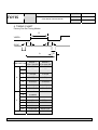
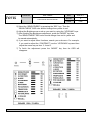
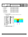
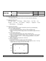
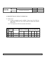
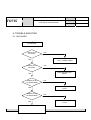
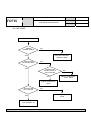
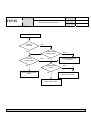
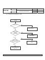
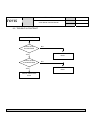
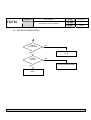
TOVIS
TOVIS P/N
MTG-1902EX
IGT P/N
69925601
DATE
03/11/02
REV.NO
0
PAGE
1/25
Color Monitor Service Manual
MODEL: MTG – 1902EX
TOVIS CO., LTD.
TOVIS P/N
TOVIS
MTG-1902EX
Color Monitor Service Manual
DATE
2002.03.11
REV.NO
0
PAGE
2/25
INDEX
1. SAFETY PRECAUTIONS ------------------------------- 3
2. SPECIFICATIONS ---------------------------------------- 4
3. TECHNICAL FEATURES ------------------------------- 5
4. TIMING CHART ------------------------------------------- 6
5. SET UP ------------------------------------------------------ 7
6. CONTROLS AND ADJUSTMENTS ------------------ 8
7. ADJUSTMENT SPECIFICATIONS------------------- 13
8. DESCRIPTION OF CIRCUIT OPERATION ------- 16
9. TROUBLE SHOOTING --------------------------------- 20
TOVIS CO., LTD.
TOVIS P/N
TOVIS
MTG-1902EX
Color Monitor Service Manual
DATE
2002.03.11
REV.NO
0
PAGE
3/25
1. SAFETY PRECAUTION
WARNING: Service should not be attempted by anyone unfamiliar with the
necessary precautions set forth in this manual. Please adhere to
these service precautions.
1-1. Some parts in this unit, such as the picture tube, have special safety-related
characteristics for X-RAY RADIATION protection. For continued safety, parts
replacement should be undertaken by referring to articles (1-2 ∼ 1-5).
1-2. Many electrical/mechanical parts in this unit have special safety-related
characteristics for protection against electrical shock and other potential
hazards. These characteristics often go unnoticed by a visual inspection and
the protection afforded by them cannot necessarily be obtained by using
replacement components rated for higher voltage, wattage, etc. Replacement
parts, which have these special characteristics, are identified in the manual
and highlighted on the schematic diagram and parts list. Before replacing
these components read the parts list carefully.
1-3. When replacing chassis in the cabinet, always be certain that all the
protective devices are installed properly, such as insulating covers, strain relief,
etc.
1-4. Before replacing the back cover of the set, thoroughly inspect inside the
cabinet to see that no stray parts or tools have been left inside.
1-5 Before returning the set to the customer always perform an ac current leakage
check on the exposed metallic parts of the cabinet, such as terminal, screw
heads, metal overlays, control shafts, etc. To be sure the set is safe to operate
without danger of electrical shock, plug the AC power cable directly into a 115V
AC outlet. (do not use a line isolation transformer during this check). Use an
AC volt- meter with 5000 or more ohms per volt in the following manner. You
cannot use a 1500 ohm, 10watt resistor, paralleled by a 0.15(uF) capacitor.
Reverse the AC plug, the AC outlet and repeat the AC voltage measurements
for each exposed metallic part. Voltage measured must not exceed 0.3V RMS.
This corresponds to 0.2mA AC. Any value exceeding this limit constitutes a
potential shock hazard and must be corrected immediately.
TOVIS CO., LTD.
TOVIS P/N
TOVIS
MTG-1902EX
Color Monitor Service Manual
2. SPECIFICATION
2-1. Picture Tube
∙Size : 19"
∙Dot Pitch : 0.26mm
2-2. Signal Input
∙Video Input : Analog, Positive Signal(0.7Vp-p)
∙Horizontal Sync : TTL Level, Positive or Negative pulse.
∙Scanning : 28KHz ~ 33KHz
∙Vertical Input : TTL Level, Positive or Negative pulse.
∙Scanning : 40∼ 150Hz
2-3. Power Supply
∙Power Input : AC100∼ 240V, 50/60Hz
∙Fuse Rating : 250V, 50T 3.15A
∙Power Consumption
Normal : less than 85W
DPMS : less than 20W
2-4. External Control :
Refer to page 7.
2-5. Operating Temperature : 0℃∼ 55℃
2-6. Operating Humidity : 10%∼ 90%(Non-condensing)
2-7. Net weight
:
17kg
TOVIS CO., LTD.
DATE
2002.03.11
REV.NO
0
PAGE
4/25
TOVIS P/N
TOVIS
MTG-1902EX
Color Monitor Service Manual
DATE
2002.03.11
REV.NO
0
PAGE
5/25
3. TECHNICAL FEATURES.
3-1. U-com (MCU) control with OSD
U-com recognizes the computer signal and signal output from the control
board connected with the wire. Hence, the circuit is simplified.
3-2. Universal AC input voltage.
The power supply operates on AC100∼ 265volt 50/60Hz for global usage.
3-3. Protection Circuit
When over-current occurs in the circuit, the protection circuit operates in
order to prevent the components from electrical shock or other risks.
3-4. Override function
The override function is designed for the normal display when the monitor is
powered on without connection from a source (No signal message).
3-5. Control panel
If you are not satisfied with the factory mode size, position or color settings,
use the control panel to program what you prefer in each resolution mode.
These adjusted settings are kept in memory even if you change resolution
mode or turn off the monitor.
3-6. I2C BUS control
It is designed by I2C BUS control for simplifying circuit.
TOVIS CO., LTD.
TOVIS P/N
MTG-1902EX
TOVIS
Color Monitor Service Manual
4. TIMING CHART
Factory Pre-Set Timing Modes.
D
VIDEO
C
E
SYNC
A
MODE 1
VGA 720*400
MODE 2
VGA 640*480
FH
31.469KHz
31.469KHz
A
31.778㎲
31.778㎲
B
3.813㎲
3.813㎲
C
1.907㎲
1.589㎲
D
25.422㎲
25.422㎲
E
0.636㎲
0.318㎲
POL.
NEGATIVE
NEGATIVE
FH
70.087Hz
59.940Hz
A
14.268ms
16.683ms
B
0.064ms
0.064ms
C
1.112ms
0.794ms
D
12.711ms
15.253ms
E
0.381ms
0.064ms
POL.
POSITIVE
NEGATIVE
ANALOG
ANALOG
DESCRIPTION
H
V
B
VIDEO
TOVIS CO., LTD.
DATE
2002.03.11
REV.NO
0
PAGE
6/25
TOVIS P/N
TOVIS
MTG-1902EX
Color Monitor Service Manual
DATE
2002.03.11
REV.NO
0
PAGE
7/25
5. SET UP
5-1. Start Up
Your monitor starts up automatically when you insert the power plug into the
power source.
5-2. 25p AMP cable Connection
AMP 25PIN
MICROTOUCH
MICROTOUCH
DRAWER
CONTROLLER
CONN.
SENSOR GLASS
TOVIS CO., LTD.
TOVIS P/N
TOVIS
MTG-1902EX
Color Monitor Service Manual
DATE
2002.03.11
REV.NO
0
PAGE
8/25
6. CONTROLS AND ADJUSTMENTS
There are four switches on the control panel.
Adjustable controls allow the best display status for individual preferences.
6-1. Key Function
① MODE
MODE - Call the Main-Menu OSD.
② SEL/DEGAUSS
SEL – Select the function (sub-Menu OSD) on the Main- Menu OSD.
DEGAUSS – perform degaussing if the OSD is not displayed.
③ DOWN/UP
-When the Main-Menu is
displayed, you can search each
function using these keys.
-When the Sub-Menu is
displayed (after you select the
function), you can change each
state of the screen using
these keys.
O.S.D Control
Sub-P.C.B
TOVIS CO., LTD.
TOVIS P/N
MTG-1902EX
TOVIS
Color Monitor Service Manual
DATE
2002.03.11
REV.NO
0
PAGE
9/25
6.2. O.S.D CONTROL METHOD
1) Control items.
Location
SUB PCB
Adjustment Method
Function
OSD Control
Brightness
Contrast
Horizontal Position
Horizontal-Size
Vertical Position
Vertical-Size
Side Pincushion
Trapezoid
Pin Balance
Parallelogram
VR control
MAIN PCB
VR301
VR501
VR502
VR503
FBT
H-MIN SIZE
H.V Adjustment
ABL Adjustment
Sub-Bright
Focus and Screen
6-3. OSD Controls
- User’s control.
A.BRIGHTNESS ADJUSTMENT.
1) Press the “MODE” key then the Main-Menu OSD should come out as
below figure.
2) Search the “BRIGHTNESS” sub-menu by using the “UP/DOWN” keys on
the Main-Menu OSD.
3) Select the “BRIGHTNESS” by pressing the “SEL” key. Then the
“BRIGHTNESS” OSD color should change from yellow to red.
4) Search “BRIGHTNESS” sub-menu using the “UP/DOWN” keys on the
Main-Menu OSD.
TOVIS CO., LTD.
TOVIS P/N
TOVIS
MTG-1902EX
Color Monitor Service Manual
DATE
2002.03.11
REV.NO
0
PAGE
10/25
5) Select the “BRIGHTNESS” by pressing the “SEL” key. Then the
“BRIGHTNESS” OSD color should change from yellow to red.
6) Adjust the Brightness as much as you want by using the “UP/DOWN” keys.
7) After finishing the Brightness adjustment, press the “MODE” key then
The “BRIGHTNESS” OSD color should change from red to yellow and
be saved automatically.
6) If you want to adjust other functions, search your sub-menu. For example,
if you want to adjust the “CONTRAST” use the “UP/DOWN” keys and then
adjust the same way as item 3, 4 and 5.
7) To finish the adjustment press the “MODE” key then the OSD will
disappear.
TOVIS CO., LTD.
TOVIS P/N
TOVIS
B. CONTRAST
C. H. POSITION
D. H. SIZE
E. V. POSITION
F. V. SIZE
G. PINCUSHION
H. TRAPEZOID
I. PARALLELOG
J. PIN BALANCE
MTG-1902EX
Color Monitor Service Manual
DATE
2002.03.11
REV.NO
0
PAGE
11/25
ADJUST SAME WAY AS ABOVE
ADJUST SAME WAY AS ABOVE
ADJUST SAME WAY AS ABOVE
ADJUST SAME WAY AS ABOVE
ADJUST SAME WAY AS ABOVE
ADJUST SAME WAY AS ABOVE
ADJUST SAME WAY AS ABOVE
ADJUST SAME WAY AS ABOVE
ADJUST SAME WAY AS ABOVE
K. COLOR ADJUSTMENT.
1) Press the “MODE” key then Main-Menu OSD come out as left
below figure.
TOVIS CO., LTD.
TOVIS P/N
TOVIS
MTG-1902EX
Color Monitor Service Manual
DATE
2002.03.11
REV.NO
0
PAGE
12/25
2) Press the “SELECT” key to adjust “RED”,”GREEN” and “BLUE”
Do this by pressing the “SELECT” key; the selected item should change
from white to its own color. (e.g., “RED” goes to red color)
3) Adjust the “RED,” ”GREEN,” or “BLUE” using the “UP/DOWN” key.
4) Press the “MODE” key to finish the color adjustment. The OSD should
return to the Main-Menu.
5) Press the “MODE” key again to finish the adjustment. The OSD will
disappear.
L. RECALL.
When you press the “RECALL” key, all user adjustment values are erased
and replaced by factory adjustment values.
TOVIS CO., LTD.
TOVIS P/N
MTG-1902EX
TOVIS
Color Monitor Service Manual
DATE
2002.03.11
REV.NO
0
PAGE
13/25
7. Adjustment Specification
7-1. Adjustment Sequence
You should allow 15 minutes for the unit to warm up before adjusting.
7-2. Adjustment Sequence
FBT High Voltage → G2 Voltage → Raster. Center → Hor. Size → Hor.
Position → Ver. Size → Ver. position → Side-pin → Trapezoid → Focus
→ White balance → Convergence
7-3. Adjustment Procedure
How to enter the Factory Mode: Press SEL and UP key simultaneously.
7-3.1. H/V voltage adjustment
1) Input the cross-hatch pattern with the 31KHz 640*480 mode.
2) After connecting a HIGH voltage meter to the ANODE, adjust VR 501 to
27kv.
7-3.2. G2 Voltage adjustment
1) Input the cross-hatch pattern with 31KHz 640*480 mode
2) After connecting a DC high voltage meter to the G2 of the CRT socket,
adjust G2 voltage to 560V ± 10V by changing SCREEN VR of FBT.
7-3.3 G/D Adjustment
Refer to controls and adjustment. (Article 6)
7-3.4 Focus adjustment
1) Input the "H" character pattern with 31KHz 640*480.
2) Adjust the focus for the best balance at each point of A, B, C, D, E as
shown below by rotating the focus VR of FBT.
3/4
A
2/4
1/4
B
E
D
1/4
C
2/4
3/4
TOVIS CO., LTD.
TOVIS P/N
TOVIS
MTG-1902EX
Color Monitor Service Manual
DATE
2002.03.11
REV.NO
0
PAGE
14/25
7-3.5. White balance Adjustment
Pre-adjustment
1) This should be carried out for at least 15 minutes.
2) Input the window pattern with 31KHz 640*480 mode.
3) Degauss the screen with a manual degaussing coil.
White Balance adjustment (Back Raster)
1) Remove the video signal
2) Adjust the sub-brightness of back raster to be 0.36±0.05FT/L with
R,G,B BIAS
3) And, adjust the color temperature to be X=0.281 ±0.02 and Y=
0.311 ±0.02 by R.G.B bias control function on OSD menu.
4) Adjust BRIGHTNESS to be 0.36FL ±0.05 F/L.
White Balance adjustment (Video)
1) Input the 20% window pattern with 31KHz 640*480mode.
2) Adjust the color temperature to be X=0.281 ±0.015 and Y=0.311
±0.02 by R.B gain on OSD menu.
3) Adjust CONTRAST to be 67FL ±5 F/L.
7-3.6. Purity and Convergence Adjustment
1) Purity Adjustment.
①Demagnetize the picture tube and cabinet using a degaussing coil.
②Turn the CONTRAST and BRIGHTNESS controls to maximum.
③Adjust the RED and BLUE bias controls to provide only a green raster
④Loosen the clamp screw holding the yoke, and slide the yoke
backwards to provide a vertical green belt (zone) in the picture
screen.
⑤Remove the Rubber wedges.
⑥Rotate and spread the tabs of the purity magnet (see figure 1) around
the neck of the picture tube until the green belt is in the center of the
screen. At the same time, center the raster vertically.
⑦Move the yoke forward slowly until a uniform green screen is obtained.
Tighten the clamp screw of the yoke temporarily.
TOVIS CO., LTD.
TOVIS P/N
TOVIS
MTG-1902EX
Color Monitor Service Manual
DATE
2002.03.11
REV.NO
0
PAGE
15/25
⑧Check the purity of the red and blue raster by adjusting the bias controls.
⑨Obtain a white raster, referring to "CRT GRAY SCALE ADJUSTMENT
⑩Proceed with convergence adjustment.
2) Convergence adjustment.
①.Receive a crosshatch pattern with a color bar signal generator.
②.Adjust the BRIGHTNESS and CONTRAST Controls for a well defined
pattern.
③.Adjust two tabs of the 4-Pole Magnets to change the angle between
them and superimpose the red and blue vertical lines in the center area
of the picture screen.
④.Turn both tabs at the same time, keeping their angles constant to
superimpose the red and blue horizontal lines at the center of the
screen.
⑤.Adjust the two tabs of 6-Pole Magnets to superimpose the red/blue
line with green one. Adjusting the angle affects the vertical lines and
rotating both magnets affects the horizontal lines
⑥.Repeat adjustment ③, ④ and ⑤. Keeping in mind red, green and
blue movement, because 4-Pole Magnets and 6-Pole Magnets are
interacted and make dot movement complex.
TOVIS CO., LTD.
TOVIS P/N
TOVIS
MTG-1902EX
Color Monitor Service Manual
DATE
2002.03.11
REV.NO
0
PAGE
16/25
8. DESCRIPTION OF CIRCUIT OPERATION
8-1. Mode control
8-1.1. H-Sync is inputted to pin 31 of IC601, V-Sync to pin 30 of IC601 for
each mode, and pin 28, 29 of IC601 output will always have positive
polarity sync.
8-1.2. The outputs from IC601 are as below (See Table 1)
Frequency
No.
Hf
kHz
Vf
Hz
1
31
70
2
31
60
Range of Frequency
Resolution
OUT PUT (MCU PIN)
Hf
(kHz)
Vf
(Hz)
CS2
39
CS1
40
720x400
28∼ 32.9
68∼ 72
L
L
L
H
640x480
"
58∼ 62
L
L
L
H
(Table 1)
TOVIS CO., LTD.
CS0 SUS41
4
TOVIS P/N
TOVIS
MTG-1902EX
Color Monitor Service Manual
DATE
2002.03.11
REV.NO
0
PAGE
17/25
8-2. Deflection Processor (IC301)
8-2.1. Horizontal section
1) Horizontal oscillation
R314 and C347 set horizontal free frequency.
Auto-sync processing can be done from 30KHz to 70KHz by means
of IC301 without any adjustment.
2) Phase shift
Horizontal phase shift is controlled by IC601 using I2C BUS control.
3) Horizontal driver output
The output pulse, which has the duty-cycle of 47%, is available at pin
26 of IC301.
This output is used for horizontal drive circuit.
4) B+ control driver output
The output pulse is available at pin 28 of IC301 and it is used for
H-scan voltage control driver.
5) X-ray protection
When the fly-back voltage rises up to an unacceptable level, x-ray
protection is activated. X-ray input pin 36 of ic601 is above 3.2v
This result is that complete line drive stage stops working.
The reset of this protection is obtained by Main power off.
8-2.2. Vertical section
1) Vertical oscillation
The free running frequency of the vertical oscillator is determined by
the capacitor C342 at pin VCAP (pin22) of IC301.
2) Vertical amplitude
Vertical amplitude is controlled by IC601 using I2C.
3) Vertical position
Vertical position is controlled by IC601 using I2C.
TOVIS P/N
MTG-1902EX
TOVIS CO., LTD.
DATE
2002.03.11
TOVIS P/N
MTG-1902EX
TOVIS
DATE
2002.03.11
RPAGE
EV.NO
18/25
0
4) Ease-west parabola
A parabola waveform is available on pin 24 of IC301 for driving the pincushion
correction stage. Amplitude of parabola waveform is controlled by IC601 using I2C.
8-2.3. B+ Regulator
B+ PWM regulator output is available on pin 28 of IC301 for driving the
B+ control stage.
8-3. Vertical Deflection (IC201)
IC201 (KA2142) is used for direct driving of vertical deflection yoke.
8-4. Horizontal scan voltage control stage
The step-up converter is used in this stage.
The output pulse at pin 28 of the IC301 is synchronized on horizontal
frequency. And this pulse is operated via buffer stage Q353, Q354
This output is rectified through D308, C328.
8-5. Horizontal deflection output stage
8-5.1. Line driver stage
As a driver device, small TR Q305(C3502E) is used.
The driver transformer T302 is equipped with a snubber circuit
(R327/C309) at the primary side to damp excessive ringing.
8-5.2. Horizontal power output stage
The horizontal power output stage is used boost-up circuit.
As a deflection transistor, the Q308 (J6820) is used.
To compensate the horizontal linearity, theT301 is connected in a series
with the horizontal DY. It is controlled by DC collector voltage of Q304,
which the base voltage of Q304 is integrated from output at pin 24 of
IC601.
.
TOVIS CO., LTD.
TOVIS P/N
TOVIS
MTG-1902EX
Color Monitor Service Manual
DATE
2002.03.11
REV.NO
0
PAGE
19/25
8-6. FBT (Fly-back Transformer)
As a driver device, IC302 (KA7500) is used.
The high voltage for CRT anode, focus, G2 voltage for CRT and 800V for
FOCUS VOLTAGE are generated by the FBT.
Also, -130V for G1 voltage, 26V for X-RAY detect voltage are extracted from
the FBT.
In this way, the supply voltage to the fly-back transformer can be proportional
to the horizontal line frequency.
8-7. ABL (Automatic Beam Limiting)
The voltage of the FBT pin10 is affected by the anode current of the FBT.
When the voltage at pin 10 is decreased, the anode current is increased
accordingly. When the anode current is increased, contrast is set at the
certain limited level (28FL in white pattern) that is set by inner voltage of
IC401.
8-8. Video amplification section
8-8.1. Video pre-amplifier (IC401)
Input video signals are amplified by means of IC401, and the amplified
signals drive the video output stage (IC402).
Video gain is adjusted by DC voltage at pin 12 for ABL control.
8-8.2. Video output stage (IC402)
The video output signal from IC401 is amplified again by IC402, and
IC402 apply video signal to each cathode of CRT.
Q405, Q406 and Q407, which is operated by I2C BUS control through
u-com, adjust cutoff voltages.
8-8.3. OSD(On Screen Display : IC403)
The OSD signal is applied from IC403 to IC402.
It is controlled by I2C BUS control line.
TOVIS CO., LTD.
TOVIS P/N
TOVIS
MTG-1902EX
Color Monitor Service Manual
DATE
2002.03.11
REV.NO
0
PAGE
20/25
9. TROUBLE SHOOTING
9-1. NO POWER
NO POWER
CHECK C112
AC LEVEL
NO
CHECK & REPLACE
F101, POWER CORD
YES
CHECK C114
DC LEVEL
NO
CHECK & REPLACE
BD101
YES
CHECK IC105
#7 WAVEFORM
NO
CHECK & REPLACE
IC105
YES
CHECK IC101
#3 WAVEFORM
NO
YES
CHECK &
REPLACE
SECONDARY VOLTAGE OF T101
TOVIS CO., LTD.
CHECK & REPLACE
IC101
TOVIS P/N
TOVIS
MTG-1902EX
Color Monitor Service Manual
DATE
2002.0311
REV.NO
0
PAGE
21/25
9-2. NO VIDEO
NO VIDEO
CHECK
SIGNAL CABLE
NO
YES
CHECK IC401
#21,24,26 PULSE
CHECK & REPLACE
SIGNAL CABLE
NO
YES
CHECK IC401
#23 DC LEVEL &
#18,19 PULSE
NO
CHECK & REPLACE
IC601, Q204
YES
CHECK & REPLACE
IC401
CHECK IC402
#1,3,5 PULSE
NO
CHECK & REPLACE
IC402
YES
CHECK & REPLACE
CRT SOCKET, G1
TOVIS CO., LTD.
TOVIS P/N
TOVIS
MTG-1902EX
Color Monitor Service Manual
DATE
2002.0311
REV.NO
0
PAGE
22/25
9-3. NO RASTER
NO RASTER
CHECK
HV & G2
NO
YES
CHECK
G1 & DC 80V
NO
CHECK & REPLACE
Q507
CHECK Q319
WAVEFORM
YES
NO
CHECK Q319
BASE
NO
CHECK & REPLACE
Q307, Q309, Q310
TOVIS CO., LTD.
YES
CHECK & REPLACE
FBT, CRT
YES
CHECK & REPLACE
Q313, Q311, D312
TOVIS P/N
TOVIS
MTG-1902EX
Color Monitor Service Manual
DATE
2002.03.11
REV.NO
0
PAGE
23/25
9-4. TROUBLE IN HORIZONTAL SIZE
H-SIZE
CHECK 45V
NO
YES
CHECK Q352
DRAIN
WAVEFORM
POWER CIRCUIT
YES
CHECK & REPLACE
Q308, D308
NO
NO
CHECK IC301
#28 WAVEFORM
CHECK & REPLACE
IC301
YES
CHECK & REPLACE
Q353, 354
TOVIS CO., LTD.
TOVIS P/N
TOVIS
MTG-1902EX
Color Monitor Service Manual
DATE
2002.0311
REV.NO
0
PAGE
24/25
9-5. TROUBLE IN CONTRAST
CONTRAST
CHECK IC401
#12 VOLTAGE
NO
CHECK & REPLACE
IC401
YES
CHECK IC401
#18 WAVEFORM
NO
CHECK & REPLACE
IC601
YES
CHECK & REPLACE
IC401
TOVIS CO., LTD.
TOVIS P/N
TOVIS
MTG-1902EX
Color Monitor Service Manual
DATE
2002.0311
REV.NO
0
PAGE
25/25
9-6. TROUBLE IN BRIGHTNESS
CHECK
G1 VOLTAGE
NO
CHECK & REPLACE
D318
YES
CHECK
HT LINE
NO
CHECK POWER BOARD
YES
CHECK & REPLACE
Q507
TOVIS CO., LTD.