1
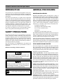
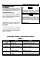
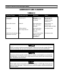
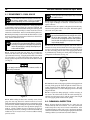
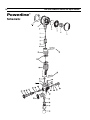
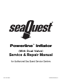
Powerline™ Inflator
(With Dual Valve)
Service & Repair Manual
for Authorized Sea Quest Service Centers
Doc. No. 42983
©1999 Sea Quest, Inc.
2
Sea Quest Powerline Service and Repair Manual
Contents
Introduction .................................................................................................................................................................... 3
Safety Precautions .......................................................................................................................................................... 3
General Procedures ........................................................................................................................................................ 3
Maintenance Schedules ........................................................................................................................................... 3
Initial Inspection & Pre-Test ................................................................................................................................... 3
Work Area & Required Tools .................................................................................................................................. 4
O-ring Removal ....................................................................................................................................................... 4
Lubrication .............................................................................................................................................................. 4
Table 1 – Required Tools ................................................................................................................................................ 4
Table 2 – Lubricant and Cleaner .................................................................................................................................. 5
Powerline Overhaul Procedures .................................................................................................................................... 6
1.1 Disassembly – Powerline inflator..................................................................................................................... 6
1.2 Cleaning & Inspection ...................................................................................................................................... 7
1.3 Reassembly – Powerline Inflator ..................................................................................................................... 8
Dual Valve Overhaul Procedures .................................................................................................................................. 7
2.1 Disassembly – Dual Valve .............................................................................................................................. 10
2.2 Cleaning & Inspection .................................................................................................................................... 10
2.3 Reassembly – Dual Valve ............................................................................................................................... 11
Final Inspection Procedures ........................................................................................................................................ 12
Troubleshooting ............................................................................................................................................................ 13
Powerline Parts List ..................................................................................................................................................... 14
Powerline Schematic .................................................................................................................................................... 15
Sea Quest Powerline Service and Repair Manual
INTRODUCTION
Sea Quest buoyancy compensators and regulators are the product of many years of research and development. Sea Quest has
utilized proven materials and design to maximize reliability and
performance.
This manual is intended only as a guide for the experienced
repair person that has completed a Sea Quest service and repair
seminar. It is not intended to educate inexperienced repair personnel or the consumer in all aspects of Sea Quest regulator and
buoyancy compensator repair. Sea Quest repair seminars are
available periodically to Authorized Sea Quest Dealers. Servicing and repair at the repair shop level mainly involves cleaning, inspection, adjustment, and replacement of worn parts.
3
GENERAL PROCEDURES
MAINTENANCE SCHEDULES
Regulators and inflation systems are subjected to a variety of
environmental elements that over time can affect the performance
of the product and as such require frequent tuning and adjustment. As an Authorized Sea Quest Dealer you are advised to
inform your staff and customers that Sea Quest regulators and
buoyancy compensators require complete servicing at least once
a year. Under certain circumstances a complete servicing is
required every 3-6 months. Some of these circumstances are:
Frequent or improper use
● Inadequate routine freshwater rinsing
● Use in dirty or polluted waters
● Rental use
● Regular use in chlorinated (pool) water
●
If you have any questions on any of the procedures, inspections, or tests, please contact Sea Quest at 877-253-3483.
SAFETY PRECAUTIONS
This manual provides step by step instructions for the disassembly, inspection, cleaning, reassembly, and testing of the
Powerline™ inflation system. It is recommended that all steps
are followed in the order given. Read each section completely
PRIOR to beginning work described in that section. This will
familiarize the repair technician with important precautions to
take during each service procedure.
Pay close attention to all WARNINGS, CAUTIONS, and
NOTES that are intended to draw your attention to items of
importance.
Definition of Warnings, Cautions, and Notes:
Recommended maintenance schedules are based on average use
under normal conditions and assume that recommended preventative maintenance and storage procedures have been followed as outlined in the Sea Quest owner’s manuals.
Advise the customer that any adjustments or servicing on Sea
Quest regulators and buoyancy compensator inflation systems
must be performed by Sea Quest, or by an Authorized Sea Quest
Dealer that has attended a Sea Quest regulator service seminar.
INITIAL INSPECTION AND PRE-TEST
Prior to servicing any B.C. or regulator, Sea Quest recommends
that a preliminary inspection of the entire breathing system
should be performed. This will help the repair technician identify any problems that may affect the Powerline Power Inflator.
Preliminary inspection should include:
First stage inlet filter - If the first stage inlet filter is discolored or corroded, the entire regulator should be completely serviced. Deposits of rust (red powder) or aluminum oxide (gray
powder) on the filter may indicate that water has entered the
SCUBA cylinder and caused internal cylinder corrosion. The
customer should be notified that their SCUBA cylinder(s) may
be in need of visual inspection, cleaning and testing. Advise
your customers to regularly inspect the inlet filter for any discoloration or corrosion.
●
Indicates a procedure or situation that may result in serious injury or death for either the technician or the user if
instructions are not followed correctly.
Indicates any situation or technique that may result in potential damage to the product, or render the product unsafe if instructions are not followed correctly.
NOTE
Is used to emphasize important points and tips.
High pressure (HP) and low pressure (LP) hoses - Inspect
the hoses carefully for any evidence of cracking, tearing, or excessive abrasion of the outer rubber covering. Remove all of
the hose protectors and examine the area around the metal fittings for any damage to the hose. Inspect the fittings for signs
of excessive corrosion.
● All chrome plated parts - Inspect for any excessive corrosion indicating weak or absent chrome plating. Also look for
any signs of peeling or flaking of the chrome plating.
● Regulator pre-test - A regulator pre-test should include all
tests outlined in the test section for each regulator. A pre-test
will assist the technician in determining if there are any specific
performance deficiencies not mentioned by the customer.
●
Sea Quest Powerline Service and Repair Manual
4
INFREQUENTLY USED BUOYANCY
COMPENSATORS
Do not assume that the Powerline or buoyancy compensator is
in good condition because of infrequent use or because it has
been in storage. Deterioration of the O-rings and corrosion can
still occur under these circumstances.
WORK AREA & REQUIRED TOOLS
Servicing and repair of the Sea Quest Powerline should be carried out in a clean well lighted work area. As each regulator is
disassembled all parts should be kept separate from parts of other
regulators. Some special tools are required for proper disassembly and reassembly of the Sea Quest Powerline. Please see
Table 1 (below) for a list of these tools.
O-RING REMOVAL
When removing O-rings, care must be taken to not damage the
regulator surfaces in contact with the O-rings. Tools used to
remove O-rings must not have any sharp edges or points that
could scratch metal sealing surfaces. Sea Quest strongly recommends that all O-ring removal tools should be made of either brass or plastic.
Do not use any petroleum based lubricants or products, or
any aerosol silicone sprays to lubricate or clean any part of
Sea Quest regulators or inflation systems. The petroleum
base or propellant gas may attack or weaken the plastic or
rubber parts. Refer to Table 2 for approved lubricants.
Sea Quest regulators and inflation systems are intended for
use in water temperatures warmer than 45ºF (7ºC). Colder
water may cause regulators to be more sensitive to a freeflow
condition and can lead to a situation that requires an appropriate response to prevent serious injury or death. Users of
Sea Quest regulators are advised to ensure that they are adequately trained to deal with a regulator in a freeflow condition or an out-of-air emergency before attempting to dive in a
cold water environment.
LUBRICATION
O-rings should be lubricated with an approved compound (please
refer to Table 2 for proper lubricants). O-rings should be lubricated only with a very light film of silicone grease. Do not use
spray (aerosol) silicone under any circumstances. The aerosol
propellant may damage the plastic and rubber components of
the regulator, and the lubricant will quickly evaporate, providing little or no lasting benefit.
REQUIRED TOOLS - POWERLINE INFLATOR
TABLE 1
Sea Quest Part No.
Description
Application
5116236
Seal/seat extractor
Removal/ installation of crown and filter
778694
Valve Core Tool
Removal/ installation of LP hose valve core
1116-10
I.P. test gauge
First stage intermediate pressure testing
9440-22
O-ring tools (Plastic or Brass)
O-ring removal & installation
41532
LP air nozzle
Parts drying
42314
T-Tool
Removal/ installation of inflator bezel
N/A
Magnifier w/ illumination
Sealing surface inspection
N/A
Ultrasonic cleaner - 60HZ, 1.3 amp
Brass & stainless steel parts cleaning
N/A
x" Hex Key
Disassembly/ assembly of purge rod & valve retainer
N/A
Inch-Pounds Torque Wrench
Torque measurement of purge rod
Sea Quest Powerline Service and Repair Manual
5
LUBRICANT AND CLEANER
TABLE 2
Lubricant / Cleaner
Recommended Type
Application
Source
Silicone Grease
(food grade)
Dow Corning 111
All O-rings,
threaded metal parts
as indicated
Dow Corning Corp
P.O. Box 1767-T
Midland, MI 48640
800-248-2481
Chemical Bath Solution
Oakite #31
Chrome-plated brass,
brass, and stainless
steel parts
Oakite Products, Inc.
50 Valley Road
Berkeley Heights, NJ 07922
Acetic Acid
50/50 mix distilled
white vinegar and water
Chrome-plated brass,
brass, and stainless
steel parts
Local grocery stores
General cleaning solution,
degreaser for plastic
and rubber parts,
leak detection
Local grocery stores
Liquid dishwashing detergent Joy®
(diluted with warm water)
DO NOT use muriatic acid for the cleaning of any parts. Muriatic acid, even when strongly diluted, can
harm chrome plating, and may leave a residue that is harmful to O-ring seals and other parts.
Aerosol spray silicone should be avoided because (1) common aerosol propellants may attack plastic
and rubber parts, and (2) because only a slight amount of silicone remains after the solvent evaporates, and provides no lasting benefit.
Silicone rubber requires no lubrication or preservative treatment. DO NOT apply silicone grease or
spray to silicone rubber parts. Doing so will cause a chemical breakdown and premature deterioration of the material.
Sea Quest Powerline Service and Repair Manual
6
POWERLINE INFLATOR
1.1 DISASSEMBLY
1.1.1 Firmly grasp the mouthpiece(25) and twist it off the body
to remove. Closely examine its condition to ensure it is free of
any tears or cuts that may cause leakage of water into the second stage, or other discomfort. Discard or set it aside to be
replaced or reused as needed.
1.1.2 Snip the clamp(12) which holds the ribbed hose(13) onto
the lower valve assembly, and work the hose off the power inflator body(30) to expose the cable retaining pin(17).
1.1.3 Press the pin out from one side with a pin punch or similar tool to release the cable assembly(11), and set the pin and
upper dual valve assembly with ribbed hose aside.
1.1.7 While holding the valve core retainer secure, gently apply
a pair of needle-nose pliers to the valve core(31), and turn it
counter-clockwise to loosen and remove. Discard the valve core
and do not attempt to reuse.
1.1.8 Closely examine the condition of the valve core retainer
to ensure it is completely free of any scratches or damage, paying particularly close attention to the areas of the external and
internal threads, and to the O-ring sealing surfaces. Discard
and replace it with new or set it aside to be reused as needed.
1.1.9 Mate both pins on the large end of a T-Tool (P/N 42314)
into two opposing holes in the inflator bezel(24). (See Fig. 2.)
While holding the tool securely engaged, turn the bezel counterclockwise to loosen and remove the bezel with the inflator valve
subassembly (items 18-24). Remove and discard the screen(18).
1.1.4 Using a small pair of pliers which are padded with neoprene or cloth, firmly grip the stem of the quick disconnect fitting(37) and turn the fitting counter-clockwise to loosen and
remove from the body. Remove the O-ring(36) from the quick
disconnect fitting and discard.
CAUTION: Do not fasten pliers or a wrench onto the nipple of
the quick disconnect fitting. Doing so may cause permanent
damage to the part, requiring its replacement.
1.1.5 From inside the body, or beneath the fitting, remove and
discard the inlet filter(35). Do not attempt to reuse.
1.1.6 Apply a x" hex key to the center of the valve core retainer(17). While holding the body secure, turn the valve core
retainer counter-clockwise to loosen and remove (see Fig. 1).
Using either the pinch method or a plastic O-ring removal tool,
carefully remove the external O-rings(32&33) from the valve
core retainer. Discard both O-rings and do not reuse.
Do not use a brass O-ring tool, pick, or other metal instrument to remove the O-rings from the sealing surfaces of the
valve core retainer. Doing so may cause permanent damage
to the part which will result in leakage if it is not replaced.
Figure 2
1.1.10 While holding the inflator bezel and button cover(23)
secure, firmly grasp the push rod housing(21) and pull it straight
away to separate from the bezel. Lift out the inflator button(22)
from one end, and turn the push rod housing over to allow the
push rod(19) to drop out. Then, remove and discard the Oring(20). Closely examine the push rod housing, push rod, and
inflator button to ensure they are in good condition, with no
visible signs of damage. Discard if any damage is found, or set
these aside if they are in reusable condition.
1.1.11 Separate the button cover from the bezel, and closely
inspect the button cover to check for any signs of damage or
wear, including tears, abrasion, or decay. If found, discard the
button cover and do not reuse.
1.1.12 Examine the inflator bezel to ensure it is in good condition, with no signs of cracking or thread damage. Discard if any
damage is found, or set aside if it is in reuseable condition.
1.1.13 While holding the oral inflator button(26) completely
depressed, apply a x" hex key to the purge rod(15), through
the upper barrel of the body, and slowly turn the purge rod
counter-clockwise with steady, controlled force until it begins
to turn freely (see Fig. 3). Maintain pressure on the button to
prevent the ejection of parts, and continue turning the purge rod
counter-clockwise to loosen and remove. Relax the oral inflator button, and set the body with button aside.
To ensure that the purge rod does not become loos-
NOTE ened, a small amount of non-permanent thread ad-
Figure 1
hesive has been applied to the threads during manufacturing or previous service. This will require that
slightly more force should be applied to initially
loosen the rod from the threads of the button on the
outside of the body.
Sea Quest Powerline Service and Repair Manual
7
1.2.2 If an ultrasonic cleaner is not available, metal parts can
be cleaned by soaking the metal parts in a chemical bath solution of Oakite #31 (see Lubricant and Cleaner Table 2) and agitating gently for 3-4 minutes. Cleaning of metal parts can also
be done by soaking in a mild acetic acid solution (distilled white
household vinegar) for 10-15 minutes.
Cleaning times in excess of those recommended
Figure 3
NOTE may damage plated parts. Never clean parts for
longer than specified by the manufacturer of the
solution used. After completion of cleaning in any
solution, thoroughly rinse parts with clean fresh
water and blow dry with low pressure (30 psig) air.
Only brass, plated brass, and stainless steel parts
should be immersed in chemical cleaning solutions.
1.1.14 Using either the pinch method or a plastic O-ring removal tool, carefully remove the O-ring(16) from the purge rod.
Discard the O-ring, and do not reuse.
Do not use a brass O-ring tool, pick, or other metal instrument to remove the O-ring from the plastic sealing surface of
the purge rod. Doing so may cause permanent damage to
the part which will cause leakage if it is not replaced.
1.1.15 Using a plastic O-ring tool, carefully remove any residue of thread adhesive from the threads of the purge rod. Closely
inspect the purge rod for any signs of damage or distortion, especially around the area of the threads. Discard or set the purge
rod aside to be replaced or reused as needed.
1.1.16 Remove the oral inflator button and spring(29) from
the body, and separate the gasket(28) from the button. Examine
the gasket for any signs of wear, damage, or decay, and discard
or set it aside to be replaced or reused as needed.
1.1.17 Closely inspect the condition of the oral inflator button
to check for any signs of damage or distortion, and to ensure
that the rubber molded insert(26) is intact and securely attached.
Discard or set the button aside to be reused as needed.
1.1.18 Closely inspect the oral inflator spring under magnification to check for any signs of damage or corrosion. If found,
discard and replace with new.
1.1.19 Closely examine the overall condition of the body, and
inspect all sealing surfaces and female threads under adequate
lighting to ensure that the body is free of any scratches, cracks,
or thread damage which may cause leakage or separation from
other components. If any damage is found, discard the body
and replace with new.
1.2 CLEANING & INSPECTION
To avoid injury, always use hand and eye protection when
handling chemical cleaning solutions.
1.2.3 After cleaning, all parts should be thoroughly rinsed in
fresh water and dried with filtered low pressure (30 psig) air.
Before performing any reassembly, it is important
NOTE to inspect all parts, both new and those that are being reused, to ensure that each part is clean and
free of any contamination, corrosion, or blemish.
1.2.4 All O-rings should be replaced at every servicing. New
O-rings should be inspected for contamination and/or imperfections, and lightly dressed with a thin film of approved lubricant prior to installation. (See Lubricant and Cleaner Table 2.)
Do not use any petroleum based lubricants or products, or
any aerosol silicone sprays on any part of the Powerline Inflator or Dual Valve Assembly. The petroleum base or propellant gas may attack or weaken plastic or rubber parts. Refer
to Table 2 for a list of approved lubricants.
1.2.5 In addition to the O-rings, the following parts should be
routinely replaced at the time of servicing:
●
●
1.2.1 All parts should be cleaned first in a warm (not over
120°F) mild soap and water solution. Use a soft nylon bristle
brush to help remove any excess or loose contamination. After
an initial cleaning in warm soapy water, metal parts should be
cleaned in an ultrasonic cleaner using the appropriate ultrasonic
cleaning solution (see Lubricant and Cleaner Table 2).
Be sure all O-rings and other rubber or plastic parts
NOTE are removed before cleaning in an ultrasonic cleaner
or chemical bath. Cleaning solutions may damage
these components.
●
●
Clamp (12)
Inlet Filter (35)
Valve Core (31)
Screen (18)
All O-rings and the above mentioned routine replace-
NOTE ment parts are included in the Powerline overhaul
service kit.
Sea Quest Powerline Service and Repair Manual
8
1.3 REASSEMBLY
Use only genuine Sea Quest parts, subassemblies, and components whenever assembling Sea Quest products. DO NOT
attempt to substitute a Sea Quest part with another
manufacturer’s, regardless of any similarity in shape, size, or
appearance. Doing so may render the product unsafe, and
could result in serious injury or death.
1.3.1 Prior to reassembly, it is important to perform a final
inspection of each part. Do not assume that a part is in acceptable condition because it has been cleaned or it is new. Check
all metal parts for excessive wear or corrosion, and closely examine all sealing surfaces which make contact with O-rings for
any signs of contamination and/or imperfections that may cause
leakage past the O-ring seal. Examine all chrome plated surfaces for any evidence of peeling or flaking of the chrome plating. Inspect all threads for galling, cross threading, excessive
wear, or damage to the chrome plating. If any parts show any
damage or excessive wear, they must be replaced with new.
It is imperative to use the specified grade and brand of thread
adhesive. Other types of thread adhesive may chemically
attack the plastic parts, and could cause them to separate.
Figure 5
1.3.2 Fit the oral inflator gasket(28) over the four guides of the
oral inflator button(27) until it is evenly seated at the base of
each guide. Set the button aside.
1.3.8 Apply an inch-pounds torque wrench with a x" hex key
to tighten the purge rod to a torque measurement of 12 inchpounds (±2). Do not overtighten.
1.3.3 Install the O-ring(16) onto the purge rod(15), into the
groove around the base of the large end.
1.3.9 Insert the narrow stem of the push rod(19) into the small
end of the push rod housing, and hold it securely in place with
the stem protruding from the opposite end.
1.3.4 Stand the inflator body(30) with the mouthpiece end facing up, and place the large end of the oral inflator spring(29)
inside the opening of the body.
1.3.5 Place the oral inflator button directly over the spring, and
rotate the button as needed to align the indexing tab with the
center groove of the body (see Fig. 4). Depress the oral inflator
button, and hold it fully depressed while turning the body over
so that the barrel faces up.
1.3.10 Place the inflator button(22) inside the top of the push
rod housing, with the opening facing down over the push rod
stem. Squeeze the push rod and inflator button between thumb
and forefinger to fit them securely together (see Fig. 6).
Figure 6
1.3.11 Slide the cylindrical screen(18) over the narrow end of
the push rod housing until it rests against the base (see Fig. 7).
Figure 4
Figure 7
1.3.6 Carefully apply only one drop of Loctite® brand, 425
grade thread adhesive to the center threads of the purge rod stem.
1.3.12 Fit the O-ring(20) over the narrow end of the push rod
housing so that it rests flush against the seating shoulder.
1.3.7 Engage the purge rod with a x" hex key, and use the hex
key to guide the purge rod through the open barrel of the inflator body and into the oral inflator button (see Fig. 5). Slowly
turn the purge rod clockwise to engage the threads of the oral
inflator button, and tighten further until lightly snug. Be careful to avoid cross threading.
1.3.13 Insert the purge rod housing into its opening in the
body, and press firmly against the button to ensure the O-ring
seats evenly between the body and the housing.
1.3.14 Fit the button cover(23) over the inflator button so that
it seats flush against the shoulder of the purge rod housing.
Sea Quest Powerline Service and Repair Manual
9
1.3.15 Carefully fit the inflator bezel(24) over the button cover
and button assembly, and press down while rotating the bezel
counter-clockwise until a click is felt. Then, turn the bezel clockwise to engage the threads and continue tightening by hand until finger snug. Be careful to avoid cross-threading.
padded with neoprene or cloth to tighten the fitting until it is
snugly seated against the body at the base. Do not overtighten.
It is important to rotate the bezel counter-clockwise, in order
to properly seat the threads before tightening it into the body.
Failure to correctly follow this step may cause permanent damage to the bezel and the body due to cross threading, which
could result in leakage if both parts are not replaced.
1.3.22 Insert the cable retaining pin(17) partly through one of
the holes of the inflator barrel of the body. Pull back the lip of
the ribbed hose(13) to expose the crimped retainer of the
cable(11), and pass the retainer over the pin.
1.3.16 Mate both pins on the large end of the T-Tool (P/N
42314) into two opposing holes in the inflator bezel. While
holding the tool securely engaged, turn the bezel clockwise until it is flush with the surface of the body (see Fig. 8). DO NOT
overtighten. Closely inspect the button cover to ensure that it is
seated evenly on all sides, and does not appear to be crimped or
partially unseated.
NOTE
If the dual valve assembly requires service, proceed
directly to the disassembly procedure on the next
page, and return to perform the following steps when
service for the dual valve has been completed.
1.3.23 When the crimped retainer of the cable is securely seated
over the pin, insert the pin through the opposite hose of the inflator barrel, so that it is flush on both sides. Fit the ribbed hose
over the inflator barrel until it is mated flush at the base of the
barrel.
1.3.24 Lightly fasten a tie-strap clamp over the ribbed hose so
that it seated evenly inside the groove near the end. Pull the end
of the tie-strap sufficiently snug, and snip the excess length with
a small pair of scissors or wire cutters.
1.3.25 Fit the mouthpiece(25) onto the inflator body, so that it
is securely seated at the base.
This concludes the reassembly of the Powerline Inflator. If
no further disassembly of the Dual Valve is required, proceed
directly to Section 3.1 — Final Inspection Procedures.
Figure 8
1.3.17 Install the larger external O-ring(33) onto the valve core
retainer(34), in the groove below the base of the threads. Install
the smaller O-ring(32) over the small end of the retainer, so that
it rests against the seating shoulder.
1.3.18 Insert the valve core(31) into the open end of the valve
core retainer, with the threaded portion facing up. Using a pair
of needle nose pliers, turn the valve core clockwise to engage
the threads of the retainer, and tighten further only until it is
snug. Be careful to avoid cross-threading or overtightening.
1.3.19 Mate the narrow end of the valve core retainer into the
threaded opening of the body, and turn clockwise to engage the
threads. Then, apply a x" hex key to the center hole of the
retainer and tighten until snug, or until the end of the valve retainer is flush with the surrounding surface of the body. Do not
overtighten.
1.3.20 Lay the inlet filter(35) inside the hole of the body which
contains the quick disconnect fitting(37). Check to ensure that
it is seated evenly below the threads, and reinstall if needed.
1.3.21 Install the O-ring(36) onto the quick disconnect fitting
at the base of the threads. Mate the quick disconnect fitting into
the inflator body, and turn clockwise by hand to engage the
threads. Continue turning clockwise by hand until it is completely threaded into the body, and apply a small pair of pliers
Sea Quest Powerline Service and Repair Manual
10
2.1 DISASSEMBLY – DUAL VALVE
If the Powerline inflator has not been removed from
NOTE the airway, perform steps 1.1.2-1.1.3 on page 6
before proceeding with the following procedure.
2.1.1 To remove the airway from the B.C., firmly grip the area
of the bladder which surrounds the connection manifold, and
hold it securely with one hand while turning the retaining collar
of the dual valve body assembly(5) counter-clockwise to loosen
and remove with the other. Remove and discard the gasket(5.1).
2.1.2 Snip the clamp(12) which holds the ribbed hose(13) onto
the body assembly, and work the hose off the lower barrel of the
body. Set the ribbed hose aside.
The outer cap is bonded to the body of the dual valve
NOTE assembly with a non-permanent adhesive. It will be
necessary to separate this bond prior to performing
further disassembly by carefully following the procedure outlined below.
2.1.3 Locate the seam that runs along the circumference
between the dual valve body and the outer cap(1), where the
cap is fastened to the body. Using the plastic handle of a medium
size screwdriver, or similar lightweight blunt instrument, rap
sharply against all points of the seam to break the adhesive bond
(see Fig. 9).
If the cap cannot be turned, repeat step 1 to break
NOTE the
adhesive bond.
2.1.5 Closely inspect the spring under magnification to check
for any signs of damage or corrosion. If found, discard and
replace with new.
2.1.6 Remove the valve plate(3) with gasket(4) from the body,
and remove the gasket from the valve plate. Discard the gasket,
and set the valve plate aside.
Further disassembly is not necessary, unless leak-
NOTE age has been detected from the exhaust valve at the
top of the dual valve body. Steps 7-9 provide instructions for removing the exhaust valve assembly
from the dual valve body for the purposes of replacing the dump plug(6).
2.1.7 Locate the two holes on opposite sides of the barrel of
the dual valve body which hold the arms of the poppet guide(9).
To remove the poppet guide and exhaust valve assembly from
the dual valve body, press the arms of the poppet guide inward
by simultaneously inserting two small probes through the opposing holes in the barrel (see Fig. 10).
Do not apply excessive force or use a hammer, mallet, or
other heavy instrument.
Figure 10
2.1.8 When the arms of the poppet guide have disengaged from
the body, firmly grasp the cable and pull the exhaust valve assembly straight out while holding the body secure. This will
pull the poppet stem(7) out of the dump plug. Remove the dump
plug and discard.
Figure 9
2.1.4 While holding the dual valve assembly secure, firmly
grasp the outer cap and turn it counter-clockwise to loosen.
While maintaining slight inward pressure to counteract the spring
pressure inside, continue turning the cap until it has disengaged
from the valve body, and remove the cap and the spring(2) beneath it. Closely examine the cap to check for any signs of
thread damage, distortion, cracking, or chemical attack that may
indicate the use of excessive force or incorrect adhesive during
previous service.
2.1.9 To replace the dump spring(8), it will be necessary to
first remove the cable hook(10) from the cable assembly(11),
and then from the poppet stem. Pull the poppet stem straight
out of the poppet guide, and discard the spring.
2.2 CLEANING & INSPECTION
2.2.1 All parts should be cleaned first in a warm (not over
120°F) mild soap and water solution. Use a soft nylon bristle
brush to help remove any excess or loose contamination. After
an initial cleaning in warm soapy water, metal parts should be
cleaned in an ultrasonic cleaner using the appropriate ultrasonic
cleaning solution (see Lubricant and Cleaner Table 2).
Sea Quest Powerline Service and Repair Manual
Be sure all O-rings and other rubber or plastic parts
are removed before cleaning in an ultrasonic cleaner
or chemical bath. Cleaning solutions may damage
these components.
NOTE
2.2.2 If an ultrasonic cleaner is not available, metal parts can
be cleaned by soaking the metal parts in a chemical bath solution of Oakite #31 (see Lubricant and Cleaner Table 2) and agitating gently for 3-4 minutes. Cleaning of metal parts can also
be done by soaking in a mild acetic acid solution (50/50 mix of
distilled white household vinegar and water) for 10-15 minutes.
Cleaning times in excess of those recommended
NOTE may damage plated parts. Never clean parts for
11
2.3 REASSEMBLY – DUAL VALVE
2.3.1 Place the dump spring(8) over the poppet stem(7), and
insert the poppet stem through the flat side of the poppet guide(9),
so that the hole through the end of the stem is visible on the
opposite side, between the two arms.
2.3.2 While holding the poppet secure with the stem extended
through the poppet guide, press the dump plug(6) onto the barbed
tip of the poppet stem until it is securely seated flush against the
flange that is directly below the barbs.
2.3.3 While holding the poppet and poppet guide between
thumb and forefinger to compress the poppet spring, install the
cable hook(10) onto the poppet stem so that it is held inside the
single-looped end (see Fig. 11).
longer than specified by the manufacturer of the
solution used. After completion of cleaning in any
solution, thoroughly rinse parts with clean fresh
water and blow dry with low pressure (30 psig) air.
Only brass, plated brass, and stainless steel parts
should be immersed in chemical cleaning solutions.
To avoid injury, always use hand and eye protection when
handling chemical cleaning solutions.
2.2.3 After cleaning, all parts should be thoroughly rinsed in
fresh water and dried with filtered low pressure (30 psig) air.
Before performing any reassembly, it is important
to inspect all parts, both new and those that are being reused, to ensure that each part is clean and
free of any contamination, corrosion, or blemish.
NOTE
Do not use any petroleum based lubricants or products, or
any aerosol silicone sprays on any part of the Powerline Inflator or Dual Valve Assembly. The petroleum base or propellant gas may attack or weaken plastic or rubber parts. Refer
to Table 2 for a list of approved lubricants.
Figure 11
2.3.4 Install the cable assembly(11) onto the hook by first working it over one end, and then spread both ends apart to work it
over the other (see Fig. 12a). When correctly installed, the cable
should be held inside the double-looped end (see Fig. 12b).
Step A
Step B
2.2.5 If overhaul of the dual valve assembly is necessary, the
following parts should be routinely replaced at the time of servicing:
●
●
Dump Plug (6)
Overpressure Relief Valve Gasket (4)
The above mentioned routine replacement parts are
NOTE included in the Powerline overhaul service kit.
Figure 12
Sea Quest Powerline Service and Repair Manual
12
2.3.5 Position the poppet guide with poppet and dump plug
outside the barrel of the dual valve body so that the larger rib
faces toward the open side of the body, away from the collar
(see Fig. 13). Lubricate the dump plug with a small amount of
water, and align the arms of the poppet guide with the grooves
inside the barrel of the body. Insert the poppet with dump plug
into the barrel only until the “ears” of the poppet guide rest above
the rim.
Figure 13
2.3.6 Squeeze the arms of the poppet guide so that the ears fit
inside the barrel, and press the poppet guide completely inward
until the ears snap into place inside their respective holes. Check
to ensure that the dump plug has passed through the top of the
barrel and remains properly seated over the end of the poppet
inside the dual valve body.
2.3.7 Install the gasket(4) onto the valve plate(3), and lay the
valve plate inside the dual valve body with the gasket facing
down.
2.3.8 Place the overpressure spring(2) directly in the center of
the valve plate, standing up.
2.3.9 Carefully apply only one drop of Loctite® brand, 425
grade thread adhesive to the center thread of the outer cap(1).
Mate the cap directly over the spring and valve plate, and press
down while turning clockwise to engage with the threads of the
body. Continue turning clockwise by hand until snug.
2.3.10 Fit the ribbed hose(13) over the cable assembly and
onto the barrel of the dual valve body, until it is mated flush at
the base of the barrel.
2.3.11 Lightly fasten a tie-strap clamp over the ribbed hose so
that it seated evenly inside the groove near the end. Position the
end of the clamp to either side, where it will not interfere with
the connection with the QD hose, and pull the end of the tiestrap sufficiently snug. Snip the excess length with small pair
of scissors or wire cutters.
2.3.12 Lay the gasket(5.1) flat inside the connection manifold,
and mate the retaining collar of the body assembly(5) directly
over it, onto the manifold. Gently turn the collar clockwise to
engage the threads, being careful to avoid cross-threading, and
hold the airway in the desired position while tightening the retaining collar by hand until snug.
Do not use tools to tighten the retaining collar onto the B.C.
manifold. Doing so may result in overtightening and/or crossthreading, and could cause permanent damage that will require replacement of the entire bladder assembly.
3.1 FINAL INSPECTION PROCEDURES
Use eye protection while performing the testing procedure.
Airborne particles can cause eye injury.
3.1.1 Verify that the first stage regulator which the Powerline
will be used with has been recently serviced, and is adjusted to
a stable intermediate pressure of 135-147 psi. Connect the
Powerline to the first stage via the specialty quick disconnect
low pressure hose, and ensure that a second stage is also
connected to function as a safety relief valve in case of an
intermediate pressure leak. All other first stage ports must be
sealed.
3.1.2 Connect the first stage to a cylinder that is filled with
3000 psi, and slowly open the valve of the supply cylinder to
pressurize the regulator.
3.1.3 Depress the inflator button of the Powerline inflator
several times to ensure that airflow is unobstructed.
3.1.4 After releasing the button, listen carefully to ensure that
the airflow has completely stopped. If internal leakage can be
heard, refer to the Troubleshooting Guide on the following page
and correct the problem as needed before proceeding.
3.1.5 Hold the inflator button depressed to fully inflate the
B.C. until the overpressure relief valve of the Dual Valve
assembly opens to release excess pressure inside the bladder of
the B.C. Check the operation of this relief valve by inflating the
B.C. repeatedly to ensure that the valve opens to relieve excess
pressure, yet closes immediately to allow the bladder of the B.C.
to remain taut and fully inflated.
3.1.6 Press the deflation button and pull the rapid exhaust cable
to ensure a rapid and unobstructed exhaust using both methods
of deflation. Fully inflate the B.C. once again, and disconnect
the Powerline from the quick disconnect hose to listen closely
for any signs of leakage.
If leakage is not immediately detected, allow the B.C.
NOTE to stand for at least one hour to ensure that none
exists.
3.1.7 If any leakage is heard or if the B.C. has begun to deflate
within one hour, fully inflate the B.C. once again with the
Powerline inflator and hold the entire B.C. submerge in fresh
water for at least one minute to determine the source of leakage.
During this time carefully observe the Powerline for any signs
of bubble formation indicating a leak, especially around the
inflator buttons and B.C. connections. If a continuous leak is
detected, the Powerline must be disassembled and examined
for damage or contamination of the seals and seating surfaces.
(Refer to the Troubleshooting Table on page 14, and correct as
needed.)
The service of the Powerline inflator with Dual Valve is now
complete. If you have any questions on any of these
procedures, please contact Sea Quest at 877-253-3483.
Sea Quest Powerline Service and Repair Manual
13
3.2 POWERLINE TROUBLESHOOTING
SYMPTOM
BC inflates slowly
(with full tank, stable IP)
Air does not vent when rapid
exhaust valve cable is pulled
Air leaks continuously from
Dual Valve when BC is inflated
External air leakage from inflator
Internal leakage from inflator
CAUSE
ACTION REQUIRED
1. Low pressure hose is obstructed.
1. Clean or replace hose.
2. Filter(35) is clogged or obstructed.
2. Replace filter.
3. Valve core(31) is clogged or corroded.
3. Replace valve core.
1. Rapid exhaust cable(11) is not properly
connected to the inflator or dual valve,
or is damaged.
1. Check condition and connections of
cable, and correct as needed.
2. Ribbed hose(13) is incorrect length and
part number.
2. Verify length and part number of
ribbed hose, and replace as needed.
1. Dump plug(6) is worn or damaged.
2. Dump plug spring(8) is damaged.
1. Replace dump plug.
2. Replace dump plug spring.
3. OPRV gasket(4) is damaged.
3. Replace gasket.
4. OPRV spring(2) is damaged.
4. Replace spring.
5. Dual valve body(5) is damaged.
5. Replace body.
1. O-ring(36/33/20/16) is damaged or worn.
1. Replace faulty O-ring.
2. Inflator button cover(23) is damaged or
installed incorrectly.
2. Disassemble and correct as needed.
3. Push rod(19) is damaged.
3. Replace purge rod.
4. Inflator body(30) is damaged.
4. Replace body.
1. Valve core(31) corroded or damaged.
1. Replace valve core.
2. O-ring(32) damaged or worn.
2. Replace O-ring.
3. Valve core retainer(34) scratched.
3. Replace valve core retainer.
4. Inflator body(30) is damaged.
4. Replace body.
Recommended treatments which require disassembly of the inflator must be performed during a
complete overhaul, according to the prescribed procedures for scheduled, annual service. Do not
attempt to perform partial service. For assistance with a problem not described here, contact a
Sea Quest Technical Advisor.
14
Sea Quest Powerline Service and Repair Manual
NOTES
Sea Quest Powerline Service and Repair Manual
15
REPAIR AND REPLACEMENT PARTS
POWERLINE INFLATOR & DUAL VALVE ASSEMBLY
Description
Part #
Item
Description
Part #
Powerline/ Dual Valve Airway
42746
20
O-ring
15034
Powerline Inflator Assy (lower unit)
42747
21
Push Rod Housing
15749
n/s
Dual Valve Assy (Acme Thread)
42743
22
Button
15747
n/s
Dual Valve Assy (Std. Thread)
42745
23
Button Cover
15086
n/s
Overhaul Kit, Powerline w/ Dual Valve 42609
24
Bezel
15746
n/s
Service & Repair Manual
42983
25
Mouthpiece
15741
26
Molded Insert
15745
1
Cap
15700
27
Oral Button
15742
2
Overpressure Spring
15613
28
Gasket
15718
3
Valve Plate
15698
29
Oral Valve Spring
15709
4
Gasket
15714
30
Body
15750
5
Body Assy, Dual Valve (Std. Thread)
42744
31
Valve Core
15504
Body Assy, Dual Valve (Acme Thread)
42742
32
O-ring
15032
Connector Seal Gasket
15309
33
O-ring
15061
34
Valve Retainer
15744
35
Filter
15628
36
O-ring
820011
37
Quick Disconnect Fitting (w/ O-ring)
090018
Item
5.1
6
Dump Plug
778559
7
Poppet Stem
778558
8
Dump Spring
15901
9
Poppet Guide
15649
10
Cable Hook
15652
11
Cable Assembly
15724
12
Clamp (2 required)
15719
13
Ribbed Hose
15734
14
Hose Clip
15735
15
Poppet, Oral Valve
15736
16
O-ring
15066
17
Cable Pin
15610
18
Filter Screen
15720
19
Push Rod
15743
Items in bold are included in the Overhaul Service Kit
16
Powerline™
Schematic
Sea Quest Powerline Service and Repair Manual