1
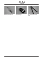
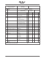
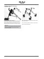
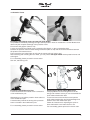
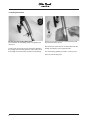
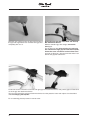
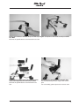
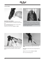
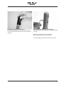
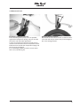
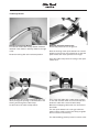
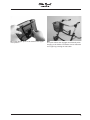
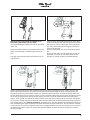
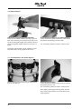
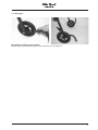
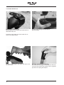
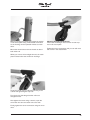
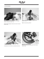
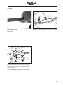
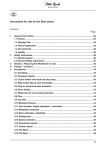
Nurmi Neo
Service Manual
Table of Contents
1 Preface ...................................................................................................................................... 2
2 Safety .... ....................................................................................................................................2
3 Maintenance Schedule and Required Tools ............................................................................. 3
4 Settings / Retrofit / Exchange .................................................................................................. 6
4.1
4.2
4.3
4.4
4.5
4.6
4.7
4.8
4.9
4.10
4.11
4.12
4.13
4.14
4.15
Anterior Frame ....................................................................................................... 6
Posterior Frame...................................................................................................... 7
Folding Mechanism................................................................................................. 8
Grip Bar ................................................................................................................. 9
Front Wheel.......................................................................................................... 12
Rear Wheel .......................................................................................................... 14
Reverse-roll Lock .................................................................................................. 15
Storage Basket .................................................................................................... 16
Driving Brake and Wheel Lock ............................................................................. 18
Gluteal Support .................................................................................................... 20
Combined Pelvic and Gluteal Support .................................................................. 20
Anti-tipper............................................................................................................. 21
Caster Swivel Lock............................................................................................... 22
Friction Brake ....................................................................................................... 24
Seat ..................................................................................................................... 25
1
1 Preface
Regular maintenance is important – it increases safety and service life of the product.
All rehab products should be checked and serviced once a year.
It is however recommended that rehab products be checked, readjusted and possibly serviced every 6
months if they
are used frequently or if the user is growing or the user‘s clinical picture changes.
For all service and maintenance work, use only original spare parts.
The service and maintenance work described in this manual should be performed by skilled specialist staff
only and not by the user of the product.
This service and maintenance manual refers to the respective spare parts catalogs and instructions for use
of the described products; therefore, please use all documents together.
Please use the maintenance schedules (check list) for duplication. Keep the completed maintenance schedules and hand over a copy to the customer.
Nurmi Neo
Instructions for Use
647G224
Spare Parts Catalog
646K73
2 Safety
For all maintenance and repair work, there are a few points you should always observe:
Use suitable tools. (refer to page 3 and the following pages)
Wear appropriate clothing as well as gloves and safety glasses, if necessary.
Secure the product to prevent it from tipping over or falling off the workbench, for example.
Study the service and maintenance instructions before beginning your work.
You should become familiar with the functions of the product first. If you do not know the product,
please first study the instructions for use before inspecting the product.
If no instructions for use are available to you, please order them from the manufacturer (refer to
the overview of all Otto Bock Branches „Otto Bock Worldwide“).
You can also download the document from our homepage under www.ottobock.de or
www.ottobock.com.
Clean / Disinfect the product before starting inspection. Please also refer to the instructions for
use regarding any care instructions or specific product inspection information.
Many of the screw fastenings use thread lock or nylock nuts. If you have to undo such screw
connections, please replace the respective nut or screw with a new thread and/or nylock nut. If
new thread lock or nylock nuts are not available, use a liquid thread lock substance with medium
strength (e.g. Loctite 241 or Euro Lock A24.20).
2
3 Maintenance Schedule and Required Tools
The following list shows you the tools and auxiliaries mentioned in the text.
Flex ratchet and
Socket wrench bits sizes 8 -19
Torque wrench
Measurement range 10 -25 Nm
Wrenches
Allen wrenches
Size 2.5 – 6
Screwdrivers
Blade width 2.5 mm
Phillips head screwdriver size 2
Plastic hammer
Hammer approx. 300 g
Water pump pliers DIN 8976
Handle width up to 32 mm
Side cutting pliers
Hand drill
Twist drill
Ø 4 mm
Sizes 8 -19
3
Stanley knife with sickle hooked
blade and standard blade
4
Liquid thread lock
“medium strength”
Pop rivet gun for rivets up to Ø
5 mm
Maintenance Schedule
for Regular Service
Item
Range
Serial Number:
Customer:
Nurmi Neo
Gait Trainers
Inspection
1.)
Function / Setting
(Refer to 647G224 Instructions for Use)
(check list)
2.)
Damages/ Deformations
3.)
Screw Connections
Nurmi Neo
4.1
Anterior Frame
4.2
Posterior Frame
4.3
4.4
4.5
x
x
- Height adjustment of the grip bar
- Anti-tipper holder
x
x
x
x
Folding Mechanism
- Folding mechanism
x
x
Grip Bar
- Depth adjustment
- Hand grip
- Grip width adjustment (optional)
- Forearm pads (optional)
- Padding for forearm pads (option)
x
x
x
x
x
x
- Tires
- Running behaviour of the wheels
- Swiveling of the wheel forks
x
x
x
x
x
Front Wheel
x
x
4.6
Rear Wheel
- Tires
- Running behavior of the wheels
x
x
x
x
4.7
Reverse-roll Lock
- Reverse-roll lock
x
x
Accessories
4.8
Storage Basket
- Basket
- Holder
x
x
x
x
4.9
Driving Brake and Wheel Lock
- Wheel Locks
x
x
4.10
Gluteal Support
- Support
- Holder
x
x
x
x
4.11
Gluteal and Pelvic Support
- Supports
- Holder
x
x
x
x
4.12
Anti-Tipper
- Anti-tipper
x
4.13
Caster Swivel Lock
- Opening and closing the caster
swivel lock
- Straight drive
- Bumper ball
x
x
x
x
x
x
4.14
Friction Brake
- Friction brake
x
x
4.15
Seat
- Folding mechanism
- Seat pad
x
x
x
x
Do the settings of the gait trainer
comply with the user‘s requirements?
The maintenance was carried out by:
on:
5
4 Settings / Retrofit / Exchange
4.1 Anterior Frame
Exchanging the Anterior Frame
Loosen and remove the marked screw connections,
left and right, between the anterior frame and the
folding mechanism (refer to 4.3) and the screw connections between the posterior and anterior frame.
Then disassemble the front wheels and the wheel
forks (refer to 4.5).
For re-assembly, please proceed in reverse order.
Use new, self-locking nuts.
Attention!
When you disassemble the frame parts, the gait
trainer folds together. Lay all parts carefully
on the work surface.
6
4.2 Posterior Frame
Exchanging the Posterior Frame and the Anti-tipper Holder
It is possible to individually exchange the right and left posterior frame on models size 1 and 2. Model size 3
allows only the complete exchange of the posterior frame.
First remove the grip bar (refer to 4.4).
Loosen and remove the marked screw connections (left figure), on the corresponding side,
between the posterior frame and the folding mechanism (refer to 4.3) and the screw connections between
the posterior and anterior frame.
Then remove the rear wheel (refer to 4.6) and the reverse-roll lock (refer to 4.7).
After loosening and removing the rear wheel, you can pull the anti-tipper holder off the posterior frame and
exchange it.
For re-assembly, please proceed in reverse order.
Use new, self-locking nuts.
Exchanging the Multifunction Part
Loosen and remove the marked screw connections
on the multifunction part.
Afterwards you can pull the posterior frame tube out
of the multifunction part.
A mandrel that prevents the turning of the posterior
frame is located in the multifunction part.
For re-assembly, please proceed in reverse order.
Exchanging the Quick-release Mechanism
First pay attention to the arrangement of the bushings and washers so that you can reassemble the
quick-release mechanism later.
Loosen and remove the knurled nut and pull the
quick-release mechanism and all the bushings and
washers out of the multifunction part.
Follow the instructions for adjusting the quick-release mechanism in the instructions for use.
For re-assembly, please proceed in reverse order.
7
4.3 Folding Mechanism
Exchanging the Folding Mechanism
First unscrew the clamping handle completely and
remove it.
Loosen and remove the screw connection between
the folding lever and the posterior frame and pull off
the folding lever with all the washers and bushings.
Finally, loosen and remove the safety bushing and
the oval head Allen screw.
Proceed in the same manner as described with the
folding mechanism on the opposite side.
For re-assembly, please proceed in reverse order.
Use new, self-locking nuts.
8
4.4 Grip Bar
Exchanging the Grip Bar (all models)
Loosen the quick-release mechanism on both sides and pull the grip bar out until the height arrest
engages.
Then press in the tripod spring button and completely remove the grip bar from the posterior frame.
For re-assembly, please proceed in reverse order.
When setting the height and depth of the grip bar, please observe the specifications in the
Instructions for Use
Exchanging the Hand Grips (all models)
Carefully cut open the hand grip with a blade and remove the hand grip from the grip bar tube.
9
Stick the new hand grip onto the grip tube and press
the grip tube against the floor until the hand grip has
completely slid on to it.
Exchanging the Grip Bar Tube Bend and the Grip
Bar Attachment Device
With the standard grip bar design, remove the
hand grips.
For the grip bar with universal grips, the mini grip
bar and the extra high grip bar with forearm pads,
loosen the screw connection of the inclined cone
and pull out the grips / forearm pads that were inserted into the grip bar tube bend.
Loosen the screw connection on the left and right grip bar attachment device and pull the grip bar tube bend
out of the grip bar attachment device.
You can now remove the grip bar attachment device from the posterior frame and replace it as described
under Exchanging the Grip Bar.
For re-assembly, please proceed in reverse order.
10
Setting the Distances between Grips and the Grip Heights of Grip Bars with Universal Grips and Mini
Grip Bars
Observe the specifications in the Instructions for Use.
Adjusting the Forearm Pads and the Grip Position
of the Extra High Grip Bar with Forearm Pads
Observe the specifications in the Instructions for
Use.
Exchanging the Padding for the Forearm Pad
Pull off the padding from the edge of the forearm
pad.
For re-assembly, please proceed in reverse order.
11
4.5 Front Wheel
5 mm
Exchanging a Front Wheel
Loosen and remove the screw connection of the
front wheel and take the front wheel out of the wheel
fork.
For re-assembly, please proceed in reverse order.
Use new, self-locking nuts.
Tighten the screws with a torque of 10 Nm.
Exchanging a Caster Fork
Loosen and pull out the screw in the caster fork and
remove the caster fork together with the screw, the
distance piece and all washers from the anterior
frame.
5 mm
Attention!
Wheels with EVA foam tires must be replaced, if
the material shows signs of cracking or damage
and when the tread becomes worn down to such
an extent that there is only 5 mm of radius left on
the outer edges of the tire.
When re-assembling, first tighten the screw only
slightly.
Place the front wheel fork in the driving direction at
an angle.
Tighten the screw with a torque of 20 Nm.
Use a new, self-locking screw.
12
Exchanging a Swivel Lock Housing
After disassembling the caster fork, you can remove the swivel lock housing from the frame tube and
replace it.
Exchanging a Thrust Piece and the Piston
First, disassemble the caster fork and the swivel lock
housing.
Unscrew the thrust piece from the piston.
Remove the piston from the frame tube.
For re-assembly, please proceed in reverse order.
13
4.6 Rear Wheel
Exchanging a Rear Wheel
Loosen and remove the screw connection of the rear wheel and remove the rear wheel from the posterior
frame. Pay attention to the spacer washer between the wheel and the frame and the collar bush in the antitipper holder.
For re-assembly, please proceed in reverse order. Use a new, self-locking nut.
Tighten the screw connection with a torque of 20 Nm .
Attention:
Wheels with EVA foam tires must be replaced, if the material shows signs of cracking or damage and
when the tread becomes worn down to such an extent that there is only 5 mm of radius left on the outer
edges of the tire. (refer to 4.5)
Exchanging an Anti-tipper Holder
Loosen and remove the screw connection of the rear
wheel and remove the rear wheel from the posterior
frame.
Remove the anti-tipper holder from the posterior
frame.
For re-assembly, please proceed in reverse order.
14
4.7 Reverse-roll Lock
30°
Exchanging a Reverse-roll Lock
Press the lock (plastic piece) as far as possible
against the compression spring, until you can take
hold of the axle with water pipe pliers.
Loosen and remove the nuts from the axle and remove the axle with the lock from the posterior frame.
Pull down from the axle the compression spring and
the lock to be exchanged.
For re-assembly, please proceed in reverse order.
Use a new, self-locking nut.
Setting a Reverse-roll Lock
Set the axle of the reverse-roll lock so that the mandrel on the axle end (as shown here) is turned approx.
30° in the driving direction.
15
4.8 Storage Basket
Retrofit of the Storage Basket
First decide whether the storage basket should be
attached in the middle or laterally shifted to the right
or left.
Fasten the locking disk at the selected position.
Mounting the Quick-release Lock
Attach both plastic bars to the grip bar.
Push the housing of the quick-release lock onto the
plastic bar and screw on the plastic bar so that the
quick-release lock faces upwards at an angle.
Insert the cable clamp into the housing of the quickrelease lock.
Wrap the cable around the locking disk and, from
above, through the opening on the backside of the
housing and through the cable clamp.
Let the ends of the cable overlap below.
First, clamp the cable with a cable clamp in place
on one side. Pull the cable on its free end taut and
fasten the cable with a second cable clamp.
Bend the overlapping cable ends over and toward
the middle.
Turn the quick-release lock on the grip rail downwards until the cable is tense. Now firmly re-tighten
the four screws in the housing.
For disassembling, please proceed in reverse order.
16
Mount the adapter plate on the basket in the uppermost position.
Use
The quick-release lock engages automatically when
hanging on the basket. The basket can be detached
once again by pressing the red button.
17
4.9 Driving Brake and Wheel Lock
Retrofit of the Driving Brake and Wheel Lock /
Assembly of the Brake Handle
First, assemble the brake handle behind the hand
grips on the grip bar.
When assemblying on an extra high grip bar with forearm pads, the brake handles are screwed onto the
perpendicular handle tubes with additional plastic
bushings.
For disassembling, please proceed in reverse order.
Pull the brake handle up to the stop.
Open the set screw in the brass insert and pull the
inner cable through the brake until the nipple hits the
brass insert. Then tighten the set screw.
Now thread the cable housing onto the cable and
fasten the brake cable with a cable tie on the frame
below the eccentric lever.
For disassembling, please proceed in reverse order.
18
Retrofit of the Driving Brake and Wheel Lock /
Assembling the Brakes (left and right)
First disassemble the reverse-roll lock as described
under 4.7.
Attach the brake bracket to the posterior frame and
fasten the bracket by re-attaching the reverse-roll
lock.
The open side of the bracket must face the non-driving direction.
Insert a screw with bushing through the lower bore
holes of the braket and close this screw connection.
Place the set collar on the longer side of the brake
bar and pull the brake bar through the upper bore
holes of the bracket.
Press an axle clamp cap on each end of the brake
bar.
Screw the set collar onto the brake bar so that the
brake bar can move up and down easily but not
laterally, or at least as little as possible laterally.
Stick a counter bearing onto each brake bar and each bushing. (Left figure) Turn a counter nut up to the
head of the longer of the two set screws and stick the set screws through the upper counter bearing. Secure these set screws with another counter nut. Stick the shorter set screw from below through the lower
counter bearing and secure it with a counter nut. Now stick the cable housing from above through the longer
set screw, the compression spring and the shorter set screw. Tense the cable until the brake bar stands
approx. 2 mm (nickle coin) above the wheel. Pull the screw die on the cable up to the set screw and tighten
the screw die. Finally attach the cable end sleeve onto the cable and carefully squeeze the cable end sleeve
with cutting pliers to fix it. Setting the Brakes: The brake force must be checked and readjusted from time to
time. Unscrewing the upper set screws increases the tension and the brake force. The set screw is secured
in place by two counter nuts. With the brake levers engaged with the last tooth, the wheels must be secured
so that the gait trainer cannot roll away (parking brake). When the brake levers are released, the wheels
should run freely.
19
4.10 Gluteal Support
Attachment of the Gluteal Support Bracket
Place the two saddle washers around the grip bar
tube. First, stick only one screw through and screw
on the mounting plate lightly. Then stick the second
screw through the saddle washers and screw it in
tightly.
Exchanging the Padding for the Gluteal Support
Loosen and remove both countersunk head screws
and detach the padding from the holder.
For re-assembly, please proceed in reverse order.
The angle of the bracket can be adjusted to meet
individual needs. Finally, tighten both screws.
4.11 Combined Pelvic and Gluteal Support
Please observe the information given in the Instructions for Use Manual.
Exchanging the Padding
Loosen and remove both carriage bolts and detach
the padding from the clip.
For re-assembly, please proceed in reverse order.
After slightly loosening the carriage bolts, the padding on the support bracket can be shifted and its
angle adjusted.
20
4.12 Anti-tipper
Retrofitting and Setting the Anti-tipper
Please observe the information given in the Instructions for Use Manual.
21
4.13 Caster Swivel Lock
Retrofitting the Swivel Lock
Disassemble the front wheels and wheel forks as
described under 4.5.
Carefully bore through the forks with a
Ø 4 mm drill bit.
Locate the catch plate onto each caster fork as
shown in the figure above.
Fasten the catch plate to the caster fork with a rivet
as shown here.
22
Adjusting the Swivel Lock Housing
The swivel lock housings can be shifted on the anterior frame tube (outer/inner position) and are guided
by means of a spring thrust piece.
Before mounting the caster forks adjust the tension
on the thrust piece using a flat bladed screwdriver
so the housing can be operated without too much
effort.
Mount the wheel forks and front wheels as described under 4.5.
Adjusting Straight-line Movement
First mount the hexagon head screws and the cap
nuts in the catch plate.
Tighten the screw connection until you can still move
the screws in the slotted holes.
When you want to drive straight forward, the catch
plate must be below the swivel lock housings.
Close the swivel lock by pulling the housing to the
outside and tightening the cap nuts.
Turn the fork so that the gait trainer will move
straight forward.
Now tighten the screw using a wrench, open the
swivel lock and turn the caster fork to the side.
Finally, tighten the screw connection using two wrenches.
23
4.14 Friction Brake
Retrofitting the Friction Brakes
Disassemble the rear wheels and the anti-tipper
holder as described under 4.6.
Locate the anti-tipper holder once again on the
posterior frame.
Replace the spacing washer ...
Place the bolt adapter and the set screw in the antitipper holder.
...with the friction plate.
Assemble the rear wheels as described under 4.6.
24
Setting the Friction Brakes
Please observe the information given in the Instructions for Use.
4.15 Seat
Retrofiting the Seat
First, remove the protective plugs from the anterior
frame tube.
Screw on the seat with the seat angle on the anterior
frame.
Exchanging the Foam Seat Padding
Loosen and remove the four screws on the lower
side of the seat padding and remove the padding
from the holder.
For re-assembly, please proceed in reverse order.
25
Hersteller/Manufacturer:
Otto Bock HealthCare GmbH
Max-Näder-Straße 15 · 37115 Duderstadt/Germany
National: Telefon 0 55 27-848 1461/1462/1463 · Fax 0 55 27-848 14 60
International: Phone +49-5527-848-1304/1562/1590/1594/3663 · Fax +49-5527-848-1676
e-mail: [email protected] · Internet: http://www.ottobock.com
Otto Bock HealthCare GmbH
Lindenstraße 13 · 07426 Königsee/Germany
Otto Bock HealthCare GmbH has been certified by the German Society for the Certification of Quality Assurance Systems (DQS)
in accordance with DIN EN ISO 9001 standard, reg. no. 779 (management system)
© Otto Bock · 647G223=GB – 11.04/1
Versandanschrift für Rücksendungen/Address for Returns