1
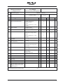
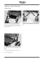
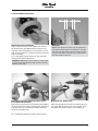
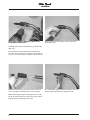
ECO
Service-Manual
Table of Contents
1 Preface ......................................................................................................................................................2
2 Safety ........................................................................................................................................................2
3 Maintenance Schedule and Required Tools .............................................................................................3
4 Adjustments / Retrofit / Replacement......................................................................................................6
4.1
4.2
4.3
4.4
4.5
4.6
4.7
4.8
4.9
4.10
4.11
4.12
4.13
4.14
Anterior Frame...........................................................................................................6
Front Wheel Attachment ............................................................................................7
Push Handles ............................................................................................................9
Posterior Frame .......................................................................................................11
Rear Wheel Attachment...........................................................................................12
Folding Scissor Construction for Back .....................................................................13
Folding Scissor Construction for Seat Bottom..........................................................13
Footrest Assembly ...................................................................................................14
Seat Bottom ............................................................................................................15
Backrest ..................................................................................................................16
Storage Bag ............................................................................................................17
Pelvic Belt................................................................................................................17
Five-point Belt..........................................................................................................18
Padding ...................................................................................................................18
1
1 Preface
Regular maintenance is important – it increases the safety and service life of the product.
All rehab products should be checked and serviced once a year.
When using a product often, however, or when a product is being used by children or adolescents who are
still growing or by patients whose clinical picture changes, it is recommended to check, readjust and possibly service the product at an interval of 6 months.
For all service and maintenance works use only original spare parts.
The service and maintenance works described in this manual should be performed by skilled specialist staff
only and not by the user of the product.
This service and maintenance manual refers to the respective spare parts catalogues and instructions for
use manuals of the described products; therefore, please use all documents together.
Please use the maintenance schedules (check list) for duplication. Keep the completed maintenance schedules and hand over a copy to the customer.
Eco-Buggy
Instructions for Use
647H446
Spare Parts Catalogue
646K44
2 Safety
For all maintenance and repair works, there are a few points you should always observe:
Use appropriate tools (refer to pages 3 & 4).
Wear appropriate clothing as well as gloves and safety glasses, if necessary.
Secure the product to prevent it from tipping over or falling off the workbench, for example.
Study the service and maintenance instructions before beginning your work.
You should become familiar with the functions of the product first. If you do not know the product,
please first study the instructions for use before inspecting the product.
If no instructions for use are available to you, please order them from the manufacturer (refer to
the overview of all Otto Bock Branches "Otto Bock Worldwide" – alternatively you can download
the document from our homepage under www.ottobock.de or www.ottobock.com).
Clean / disinfect the product before starting inspection. Please also refer to the Instructions for
Use Manual regarding any care instructions or specific product inspection information.
Many of the screw fastenings use thread lock or nylock nuts. If you have to undo such screw
fastenings please replace the respective nut or screw with a new thread lock and/or nut. If new
screws or nuts with thread lock are not available use a liquid thread lock substance with medium
strength (e.g. Loctite 241 or Euro Lock A24.20).
2
3 Maintenance Schedule and Required Tools
The following list shows you the tools and auxiliaries mentioned in the text.
Reversible ratchet handle wrench
and sockets, sizes 8 + 10
Allen wrenches, sizes 3 + 4
Wrenches, sizes 8 + 10
Pop rivet gun for rivets up to
Ø 5mm
Water pump pliers DIN 8976,
gripping width up to 32 mm
Phillips head screwdriver, size 2
Plastic hammer
Hammer, approx. 300 g
3
Pin punches Ø 3 mm + Ø 4 mm
Hand drill
Twist drills Ø 5 mm + Ø 6 mm
Stanley knife with sickle hooked
blade and standard blade
Workbench as well as a vice with
plastic jaws and rubber insert
(e.g. HR11290048)
Liquid thread lock "medium
strength"
Brush and standard grease
4
Maintenance Schedule
for Regular Service
Item
Eco-Buggy
Pediatric Postural Positioning System
Component (group)
Serial no.:
Eco-Buggy
Customer:
Inspection (check list)
1.)
Function / setting
(refer to 647H446 Instructions for Use)
2.)
Damages/ deformations
3.)
Screw connections
- Folding
4.1
Anterior frame
x
x
4.2
Front wheel attachment
- Caster swivel lock
- Spring system
- Tyres
- Running behaviour of the
wheels
x
x
x
x
4.3
Push handles
- Folding guards
- Rubber hand grips
x
x
x
4.4
Posterior frame
x
x
4.5
Rear wheel attachment
- Wheel lock mechanism
- Elastomer spring system
- Tyres
- Running behaviour of the
wheels
x
x
x
x
x
x
4.6
Folding scissor construction
for back
- Folding
x
x
4.7
Folding scissor construction
for seat bottom
- Folding
x
x
4.8
Footrest assembly
- Footplate lock
- Elevating and swing away
functions
x
x
x
x
4.9
Seat bottom
- Folding scissor construction
- Nylon seat
x
x
x
x
4.10
Backrest
- Folding scissor construction
- Nylon back
- Angle adjustment
x
x
x
x
x
x
4.11
Storage bag
- Snap fasteners
x
4.12
Pelvic belt
- Belt buckle
x
4.13
Five-point belt
- Belt buckle
x
4.14
Padding
x
Do the settings of the rehab
buggy comply with the user‘s
requirements?
The maintenance was carried out by:
on:
5
4 Adjustments / Retrofit / Replacement
4.1 Anterior Frame
Replacing the left or right Anterior Frame
First remove the footrest assembly as described
under section 4.8 and the front wheel attachment as
described under 4.2.
Next, loosen and remove the screw connections
(Arrowed) between the anterior frame and the seat
as well as between the anterior frame and the push
handle.
For re-assembly, please proceed in reverse order.
Use new, self-locking nuts.
6
Loosen and remove the screw connections between
the anterior frame and the folding scissor construction.
4.2 Front Wheel Attachment
5 mm
Replacing the Front Wheels
Press on the wire bow in the wheels‘ hub and pull
the wheel off the axle. Repeat this process for the
opposite wheel. Pay attention to the spacers on the
axle, which provide for a distance between the wheel
and the housing.
For re-assembly, put the wheel onto the axle while
holding the wire bow depressed.
5 mm
Attention:
Wheels with EVA foam tyres must be replaced, if
the material shows signs of cracking or damage
and when the tread becomes worn down to such
an extent that there is only 5 mm of radius left on
the outer edges of the tyre.
Attention: Slightly pull at the wheel to check if the
quick-lock has engaged and the wheel is securely
seated on the axle.
Replacing the Lower Swivelling Part of the
Front Wheel Attachment
After having removed the front wheels press together
the hooks under the lower swivelling part using pliers
and slide the lower swivelling part downwards off
the upper swivelling part.
Replacing the Swivel Lock
After having loosened the lower swivelling part you
can easily pull the swivel lock (arrowed) out of the
rail guide and replace it with a new swivel lock.
For re-assembly, please proceed in reverse order.
7
Replacing the Upper Swivelling Part of the
Front Wheel Attachment
Drive the rivet into the anterior frame using a pin
punch (Ø 4 mm).
Carefully drill out the rivet head using a new drill bit
(Ø 6 mm).
If the nail in the rivet protrudes above the head of
the rivet, use a pin punch to drive the nail inwards so
you can use the rivet hole for guidance of the drill bit.
Repeat the process for the removal of the other rivets, so the upper swivelling part can be removed.
When replacing the upper swivelling part do not forget to reinsert the solid core into to the upper swivelling part before attaching it with rivets.
8
For re-assembly, plug all elements together and fasten the upper swivelling part using two rivets.
4.3 Push Handles
Replacing the left or right Push Handle
First loosen and remove the screw connections
between the push handle and the folding scissor
construction as well as between the push handle
and the tilt mechanism of the backrest.
Next, loosen and remove the screw connections
between the push handle and the posterior frame as
well as between the push handle and the anterior
frame.
Remove the push handle.
For re-assembly, please proceed in reverse order.
Use new, self-locking nuts.
Replacing a Rubber Hand Grip
Carefully cut open the rubber hand grip using a stanley knife and remove the old rubber hand grip.
9
Using a knife remove the residue of the old glue or
rubber from the handle surface and from inside the
tube.
Using a clean cloth and solvent, fully degrease the
end of the push handle tube.
Open the two part adhesive sachet. Use the spatula
to squeeze out all the contents of the sachet into the
centre of the mixing card and mix the components
for approx. 30 seconds.
Apply half of the adhesive into the rubber hand grip
using the spatula. Evenly distribute the adhesive
in the rubber hand grip up to a depth of approx.
4-5 cm.
Slide the rubber hand grip onto the push handle
rotating it through 180° as it is pushed on.
10
Important: The push handle should not be used
for at least 24 hours so as to allow full curing of the
adhesive!
4.4 Hinterrahmen
Replacing the left or right Posterior Frame
First remove the rear wheels as described under
section 4.5 and pull the rear axle out of the rear
wheel attachment.
Loosen and remove the screw connections between
the posterior frame and the push handle.
With a few models, the rear axle is additionally fixed
with a set screw. Loosen this set screw and then pull
the axle out of the rear wheel attachment.
Next, loosen and remove the screw connections between the the posterior frame and the folding scissor
constructions as well as between the posterior frame
and the seat tubes.
Remove the posterior frame.
For re-assembly, please proceed in reverse order.
Use new, self-locking nuts.
11
4.5 Rear Wheel Attachment
5 mm
Replacing the Rear Wheels
Press on the wire bow in the wheels‘ hub and pull
the wheel off the axle. Repeat this process for the
opposite wheel. Pay attention to the spacers on the
axle, which provide for a distance between the wheel
and the housing.
For re-assembly, put the wheel onto the axle while
holding the wire bow depressed.
5 mm
Attention:
Wheels with EVA foam tyres must be replaced, if
the material shows signs of cracking or damage
and when the tread becomes worn down to such
an extent that there is only 5 mm of radius left on
the outer edges of the tyre.
Attention: Slightly pull at the wheel to check if the
quick-lock has engaged and the wheel is securely
seated on the axle.
Replacing the Rear Wheel Attachment
Loosen and remove the screw connection between
the rear wheel attachment and the posterior frame.
Remove the rivets as described under Replacing
the Upper Swivelling Part of the Front Wheel
Attachment. However, use a drill bit Ø 5 mm and a
pin punch Ø 3 mm.
For re-assembly, please proceed in reverse order.
Use new, self-locking nuts.
12
Replacing the Wheel Lock Lever Extension
Loosen and remove the screws on either side of
the wheel lock lever extension using a Phillips head
screwdriver and remove the wheel lock lever extension.
For re-assembly, please proceed in reverse order.
4.6 Folding Scissor Construction for Back
Replacing the Folding Scissor Construction
for Back
First loosen and remove the screw connections between the folding scissor construction and the push
handles.
Next, loosen and remove the screw connections
between the folding scissor construction and the
posterior frame and remove the folding scissor construction.
For re-assembly, please proceed in reverse order.
Use new, self-locking nuts.
4.7 Folding Scissor Construction for Seat Bottom
Replacing the Folding Scissor Construction
for Seat Bottom
Loosen and remove the screw connections between
the folding scissor construction and the posterior
frame.
Next, loosen and remove the screw connections
between the folding scissor construction and the
anterior frame and remove the folding scissor construction.
For re-assembly, please proceed in reverse order.
Use new, self-locking nuts.
13
4.8 Footrest Assembly
Replacing the Footrest Assembly - Adjusting
the Lower Leg Length
Loosen and remove the four plastic screws from the
holders. Now you can remove the footrest or adjust
the height be using other bore holes.
For re-assembly, snugly tighten the four screws.
14
Replacing the Footplates
Loosen and remove the two screws (Arrowed) and
remove the stop blocks.
Now pull the footplates off the footrest bars.
For re-assembly, please proceed in reverse order.
For disassembly of the footplates the footrest bars
need not be disassembled from the anterior frame.
4.9 Seat Bottom
Replacing the Seat Bottom
Loosen and remove the screw connections (Arrowed) on either side between the seat tube and
the anterior frame, between the seat tube and the
backrest, and between the seat tube and the posterior frame.
Remove the seat.
For re-assembly, please proceed in reverse order.
Replacing the Nylon Seat Upholstery
Loosen and remove the screw connections (Arrowed) on either side of the seat bottom and pull the
seat tubes out of the nylon seat.
For re-assembly, please proceed in reverse order.
Use new, self-locking nuts.
Use new, self-locking nuts.
Adjusting/Readjusting the Seat Upholstery
Models from approx. 10/03 (serial numbers 004xxxxxx) feature a readjustable seat upholstery.
First loosen the tensioning scissor construction
under the seat bottom. Now open the hook & loop
closures and adjust the tension as desired.
15
4.10 Backrest
Replacing the Backrest
Loosen and remove the screw connections (Arrowed) between the seat tube and the backrest
as well as between the pushbar and the backrest
adjustment, on either side of the backrest.
Remove the back.
For re-assembly, please proceed in reverse order.
Replacing the Nylon Back Upholstery
Loosen and remove the four screw connections (Arrowed) on either side of the backrest and remove the
back upholstery from the back tubes.
Pull the two plastic reinforcement splints out of the
back upholstery and reuse them.
For re-assembly, please proceed in reverse order.
Use new, self-locking nuts.
Use new, self-locking nuts.
Shifting the Backrest (seat depth)
After loosening and removing the screw connections
(Arrowed) on either side of the backrest, you can
shift the backrest by 5 cm and reattach the backrest
there with the screw connections.
Use new, self-locking nuts.
16
Replacing an Angle Adjustment
(Adjustment Kit)
Loosen and remove the screw connections (Arrowed) and remove the angle adjustment.
For re-assembly, please proceed in reverse order.
Use new, self-locking nuts.
4.11 Storage Bag
Replacing the Storage Bag
Undo the snap fasteners on either side of the storage bag.
Open and remove the nuts (Arrowed) and remove
the storage bag.
For re-assembly, please proceed in reverse order.
4.12 Pelvic Belt
Replacing the Pelvic Belt
First slide the plug element of the belt buckle off the
pelvic belt. Loosen the screw connections (Arrowed)
and pull out the pelvic belt from between the back
tube and the back upholstery.
For re-assembly, please proceed in reverse order.
17
4.13 Five-point Belt
Please observe the information given in the product‘s Instructions for Use Manual.
4.14 Padding
Please observe the information given in the product‘s
Instructions for Use Manual.
18
Hersteller/Manufacturer:
Otto Bock HealthCare GmbH
Max-Näder-Straße 15 · D-37115 Duderstadt
National: Telefon (0 55 27) 848 1461/1462/1463 · Fax (0 55 27) 848 14 60
International: Phone +49-5527-848-1304/1562/1590/1594/3663 · Fax +49-5527-848-1676
e-mail: [email protected] · Internet: http://www.ottobock.com
Otto Bock HealthCare GmbH
Sälzerstraße 16 · D-56235 Ransbach-Baumbach
Otto Bock HealthCare GmbH has been certified by the German Society for the Certification of Quality Assurance Systems (DQS)
in accordance with DIN EN ISO 9001 standard, reg. no. 779 (management system)
© Otto Bock · 647G210=D – 03.04/1
Versandanschrift für Rücksendungen/Address for Returns