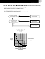
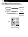
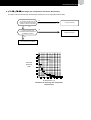
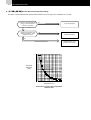
1
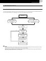
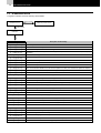
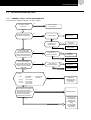
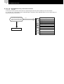
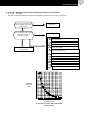
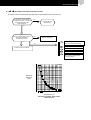
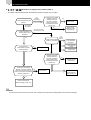
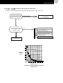
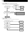
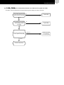
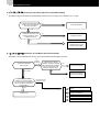
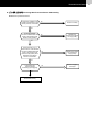
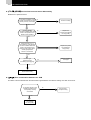
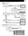
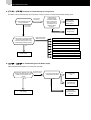
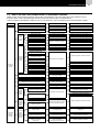
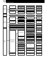
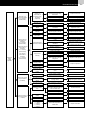
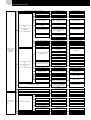
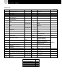
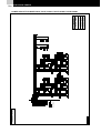
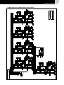
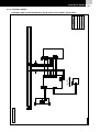
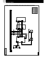
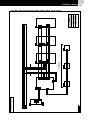
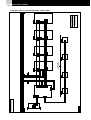
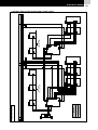
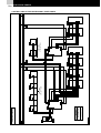
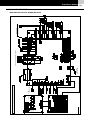
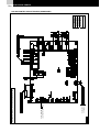
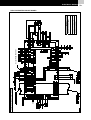
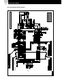
Service Manual Maintenance Instructions. AIR COOLED WATER CHILLERS -SCREW TYPERCUE40AG1-400AG1 (R407C) Cooling Capacity 108 kW - 1068 kW 0 TABLE OF CONTENTS 1.TROUBLESHOOTING ................................................................................................................. 1 1.1. 1.2. 1.3. 1.4. OUTLINE OF FAILURE DIAGNOSIS .............................................................................................................2 ALARM INDICATION.................................................................................................................................3 FAILURE DIAGNOSIS METHOD4 ANALYSIS AND COUNTERMEASURE OF ABNORMAL RUNNING .......................................................................21 2. ELECTRICAL WIRING................................................................................................................ 27 2.1. CUSTOMER WIRING .................................................................................................................................27 2.2. WIRING DIAGRAM ....................................................................................................................................29 2.3. MAIN CIRCUIT BOARD ..............................................................................................................................41 TROUBLESHOOTING 1/1 1 TROUBLESHOOTING 1.1. OUTLINE OF FAILURE DIAGNOSIS In the case of abnormality, alarm lamp of remote control and alarm LED on the control panel are ON. And segment indication on the control panel is flickering. For stopping the unit, put it into stop operation without power OFF. Alarm occur Segment Indication: Abnormality Code Flickering. Alarm Indication: ON (Local Side) Remote Control Run Indication: ON Remote Control Alarm Indication: ON (Remote Side) Stop Operation Yes Is abnormality code in segment indication confirmed? No Abnormality code is indicated by indication mode of alarm Occurence Data. Abnormality code is indicated in the segment indication. Take proper measure according to the alarm position NOTE: - After the stop operation, alarm indication is turned off and initial status 88 is displayed. And then abnormality code, which activated before is indicated by “Indication Mode of Alarm Occurrence Data”. - When the power turns off and turns on, the indication is initial status. And then abnormal code, which activated before is indicated by “Indication Mode of Alarm Occurrence Data” 1/2 TROUBLESHOOTING 1.2. ALARM INDICATION 7-Segment indication shows the following abnormalities Without indication Unit does not run Check the power source With indication Check the 7-segment indication Alarm Code No.1~6 cycles Description of abnormality []~[] Excessively Low Pressure []~[] Low Pressure Protection by Suction Gas Thermistor []~[] Excess Low Temperature of Cooler Inlet Refrigerant []~[] Freezing Protection Control by Cooler Inlet Refrigerant Temperature and excess low suction pressure (retry operation) [] Activation of Freezing Protection Control []~[] Activation of High Pressure Switch []~[] Activation of Discharge Gas Thermostat []~[] Activation of Compressor Internal Thermostat []~[] Phase Abnormally []~[] Error communication between Ctrl. PCB and Fan Speed Ctrl. PCB’s (Low Ambient Fan Speed Ctrl. Option) []~[] Failure of Thermistor set before Expansion Valve (Open / Short) []~[] Activation of Fan Motor Internal Thermostat [] Failure of Ambient Temperature Thermistor (Open / Short) []~[] Failure of Cooler Inlet Refrigerant Thermistor (Open/Short) []~[] Failure of Discharge Gas Thermistor (Open/Short) []~[] Failure of water oulet temperature thremistor i cooler siter (Open / Short) []~[] Failure of Suction Gas Thermistor (Open / Short) []~[] Failure of Discharge Gas Pressure Sensor (Open / Short) []~[] Failure of Suction Gas Pressure Sensor (Open / Short) [] Error communication between Ctrl. PCB (PCBC1, PCBC2) [] Failure of Water Inlet Temperature (Open / Short) [] Failure of Water Outlet Temperature Thermistor (Open / Short) [] Failure of Water Outlet 2 Temperature Thermistor (Open/Short) [] Failure of Water Outlet 3 Temperature Thermistor (Open/Short) [] Malfunction []~[] Activation of Differential Pressure Control []~[] Activation of Thermal Relay for Compressor []~[] No Feedback Signal from Water Pump []~[] Alarm of Excessively High Water -Temperature [] [] " " - " " : Flickering. Alarm of Water Failure (Differential Water Pressure Switch Option) Activation of Additional Protection Device (Option) XX - XX : SEG1-SEG2 TROUBLESHOOTING 1.3. FAILURE DIAGNOSIS METHOD 1.3.1. GENERAL CHECK OF FAILURE DIAGNOSIS. In the case of no segment indication, unit cannot operate. Is 220-240V supplied to the unit?: No Check the power source switch Yes Is 220-240V supplied to transformer primary side? No Is fuse broken? Yes No Yes Is R phase or S phase failure? Yes No Is the wiring of transformer broken? Yes Replace transformer No Yes Is 26.7V in PIN1~PIN2, 17.6V in PIN3~PIN4, 17.6V in PIN5~PIN6 of the printed circuit board for CPU (PCBc) connector CN2B and CN2C Wiring check and repair Wiring check No Is 30V in PIN1~PIN2, 16.3V IN PIN3~PIN4, 19.6V IN PIN5~PIN6 of the printed circuit board for CPU (PCBc) connector CN2A Replace fuse Wiring check Connector check No Is the wiring of transformer broken? No Yes Yes Replace transformer Wiring check Connector check Is voltage in each test PIN of printed circuit board for CPU 5 V part VCCO5-GND1 V5B-GND1 +15V part - 15V part 24V part VCC15T-GND1 VCC15T-GND1 VCC24-GND1 VCC24T-GND1 VCCO5N-GND1 VCCR-GND1 No Power Source Circuit Malfunction Replace Printed Circuit Board for CPU (PCBC) Yes Are connector FCN1, FCN2 on the printed circuit board for CPU (PCBC) and Printed Circuit Board for Display and Operation (PCBA, PCBB) correctly connected and checked loose connection? Yes No Connector Repair Check Printed Circuit Board for Display and Operation (PCBA, PCBB) Check Printed Circuit Board for CPU (PCBC) 1/3 1/4 TROUBLESHOOTING ! [] ~ [] Excessively Low Suction Pressure In case of the suction pressure is less than 0.31 Mpa during 90 seconds, the unit will stop at once and indicate “[]~[]”. 3 minuts later, the unit will start again. This Alarm code is indicated when it occurs 3 times during 30 minutes (It will retry until 2 times.). Is connector CN 29Ps on the printed circuit board for relay (PCBD) correctly connected? Yes Shortage of Refrigerant Gas Leakage Clogging of expansion valve Clogging of strainer No Clogging of low pressure side pipe Stop Valve malfunction Shortage of Water Wiring Check Pump reverse rotation Air mixed Deposits on Water Cooler Plates Clogging of Water Strainer TROUBLESHOOTING ! [] ~ [] Low Pressure Protection by Suction Gas Thermistor This alarm code is indicated when the suction temperature is lower than -2°C during 10 seconds. Is the wiring of connector in the Printed Circuit Board for Relay (PCBD) correct? No Plug correctly and repair wiring Yes Pull out connector and measure thermistor resistance. Is resistance correct? Yes Yes No Replace thermistor Check the water flow rate.(Check temperature of inlet and outlet.) Clogging of water strainer Pump reverse rotating check Check Printed Circuit Board for Relay (PCBD) Check the air mixing Check chilled water thermostat setting value (Within the working range) Shortage of refrigerant Gas Leakage Clogging of expansion valve Clogging of strainer Clogging of low pressure pipe Malfunction of Check valve Malfunction of Expansion Valve Thermistor resistance (KΩ) Temperature (°C) Thermistor for Suction Gas Temperature characteristics 1/5 1/6 TROUBLESHOOTING ! []~[] Excess Low Temperature of Cooler Inlet Refrigerant In case of the cooler inlet refrigerant temperature is lower than -3°C during 10 seconds, the unit will stop at once and indicate “[]~[]”. 3 minutes later, the unit will start again. This alarm code is indicated when it occurs 3 times during 30 minutes (It will retry until 2 times) Is connector CN27Tr2 on the printed circuit board for Relay (PCBD) correctly connected? No Plug correctly and repair wiring Yes Pull out connector and measure thermistor resistance. Is resistance correct? No Replace Thermistor Yes Yes Check printed circuit board for Relay (PCBD) Check water flow rate (Check the temperature of Inlet and Outlet) Check pump reverse rotation Check water strainer clogging Check air mixing Check Chilled water thermostat setting value (It shall be within the unit working range) Shortage of Refrigerant Gas Leakage Clogging of low pressure side pipe Clogging of expansion valve Check Valve Malfunction Expansion Valve Malfunction TROUBLESHOOTING 1/7 ! [] Activation of Freeze Protection Control This alarm code is indicated when the water inlet or outlet temperature is lower than 2°C. Is connectors on the Printed Circuit Board correctly connected? PCBC:CN4,CN6,CN7,CN3 PCBD:CN23Te2 No Plug correctly and repair wiring Yes Pull out connector and measure thermistor resistance Is resistance correct? No Replace Thermistor Yes Check water flow rate (Check the temperature of Inlet and Outlet) Yes Check pump reverse rotation Check printed circuit board Check water strainer clogging Check air mixing Check Chilled water thermostat setting value (It shall be within the working range) Thermistor resistance (KΩ) Temperature (°C) Thermistor for Water Temperature characteristics 1/8 TROUBLESHOOTING ! ] ~ [] Activation of high pressure switch (PSH1~6) This alarm code is indicated when the discharge pressure is higher than 2.74 Mpa. Is 220-240V the voltage between connector PCN203 PIN1 and connector PCN 203 PIN3 on the Printed Circuit Board for Relay (PCBD1~6)? Yes (Activate immediately) Is alarm activated just after running? No (Activate after a while) Is alarm activated in 3 minutes after running operation? Yes PCBD Check Wiring Check (breaking of wire, wrong wiring) No No (Activate a while after Compressor ON) Yes Is high pressure switch (PSH1~6) activated? Yes (PCB is normal) Check clogging in air side heat exchanger No Is high pressure switch (PSH1~6) reset button activated? High Pressure Check No Reset Cycle Check Yes Is 220-240V the voltage between connector PCN203 PIN1and connector PCN 203 PIN3 on the Printed Circuit Board for Relay (PCBD1~6)? No Wiring check (breaking of wire, wrong wiring) Yes Is 220-240V the voltage between connector PCN203 PIN1 and connector PCN 203 PIN3 on the Printed Circuit Board for Relay (PCBD1~6)? No Wiring Check Check Printed Circuit Board for Relay (PCBD1~6) Yes Check Printed Circuit Board for Relay ( PCBD 1~6) NOTE: To check the nominal value for pressure refer to safety and control device setting table to the technical catalogue TROUBLESHOOTING ! [] ~ [] Activation of Discharge Gas Thermostat This alarm code is indiacted when the temperature in discharge pipe is higher than 140ºC Is connector CN24Td on the printed circuit board for relay (PCBD) correctly connected Wiring check (breaking of wire, wrong wiring) Yes Pull out connector and measure thermistor resistance. Is resistance correct? Yes Shortage of Refrigerant Gas Leakage Check Valve Malfunction Clogging of expansion valve No Expansion valve opening check Clogging of strainer Check PCBD Replace Thermistor Thermistor resistance (KΩ) Temperature (°C) Thermistor for Discharge Gas Temperature characteristics 1/9 1/10 TROUBLESHOOTING ! [] ~ [] Activation of Compressor Internal Thermostat This alarm code is indicated when the compressor internal thermostat is higher than 115ºC Is 220-240V the voltage between connector PCN204 PIN1 and connector PCN 204 PIN3 on the Printed Circuit Board for Relay (PCBD) ? Yes Is alarm activated just after running? No (Activate after a while) Yes No No (Printed Circuit Board is normal) Is 220-240V the voltage between connector PCN204 PIN1 and connector PCN 204 PIN3 on the Printed board for Relay (PCBD)? Check Printed Circuit Board for Relay (PCBD) Wiring Check (breaking of wire, wrong wiring) Excessive or short power source voltage Interphase of power source voltage is imbalanced. Compressor motor is locked Yes Insulation of compressor motor is lowered Wiring Check ! [] ~ [] Phase Abnormality This alarm code is indicated when the power source phase failure or reverse phase occur. Is power source phase failure or reverse phase? Yes (Phase Failure, Reverse Phase) Power Supply, Wiring Check No Is printed circuit board for relay (PCBD) connector R.S.T correctly connected? No Connection repair Yes Is the power source of connector R.S.T part phase failure or reverse phase? Yes Repair to correct phase No (Correct Phase) Check printed circuit board for relay (PCBD) TROUBLESHOOTING ! []~[] Error comunication between Ctrl. PCB and Fan speed Ctrl. PCB This alarm code is indicated when the transmission signal is missing more than 5 seconds. Is connector CN14A on the printed circuit board for CPU (PCBC) correctly connected? No Plug correctly and repair wiring Yes Is connector on the printed circuit board for Fan speed control (PCBE) correctly connected No Plug correctly and repair wiring Yes Check the Printed circuit board for Fan speed control (PCBE) Normal Replace the printed circuit board for CPU (PCBC) Abnormal Replace the printed circuit board for Fan Speed (PCBE) 1/11 1/12 TROUBLESHOOTING ! []~[] Thermistor set before Expansion Valve Abnormality This alarm code is indicated when the thermistor resistance is out of range (72 Ω ≤ Resistance ≤ 179 kΩ) Is printed circuit board for relay (PCBD) connector CN22Te1 correctly connected? No Plug, Wiring Repair Yes Disconnect connector and measure resistance. Is the resistance correct? No Replace thermistor Yes Replace printed circuit board for relay (PCBD) ! []~[] Activation of Fan Motor Internal Thermostat This alarm code is indicated when the fan motor internal thermostat is higher than 135ºC Yes (Activate immediately) Is alarm activated just after running? No (activate after a while) Is 220-240V the voltage between connector PCN206 PIN1 and connector PCN206 PIN3 on the Printed Circuit Board for Relay (PCBD)? Yes Check Printed Circuit Board for Relay (PCBD) No Wiring check (breaking of wire, wrong wiring) Is 220-240V the voltage between connector PCN206 PIN1 and connector PCN206 PIN3 on the Printed circuit board for Relay (PCBD)? Yes Wiring check No (Printed Circuit Board is normal) Excessive or short power source voltage Interphase of power source voltage is imbalanced Fan Motor is locked Insulation of Fan Motor is lowered TROUBLESHOOTING 1/13 ! [] [] [] [] [][]~ [] Temperature Thermistor Abnormality This alarm code is indicated when the thermistor resistance is out of range. (Water Temperature Thermistor: 240 Ω ≤ Resistance ≤ 39 kΩ) (Ambient Temperature Thermistor: 240 Ω ≤ Resistance ≤ 600 kΩ) [] Inlet Water Temperature Thermistor Abnormality [] [] [] Outlet Water Temperature Thermistor Abnormality [] Ambient Temperature Thermistor Abnormality No Is connector on the printed circuit board for CPU (PCBc) correctly connected? Plug, Wiring, Repair Yes Pull out connector and measure thermistor resistance. Is resistance correct? No Replace thermistor Yes Replace printed circuit board for CPU (PCBC) [] [] [] []~ [] [] Thermistor resistance Thermistor resistance (KΩ) (KΩ) Temperature (°C) Thermistor for Water Temperature characteristics 1/14 TROUBLESHOOTING ! []~ [] Cooler Inlet Refrigerant Temperature Thermistor Abnormality This alarm code is indicated when the thermistor resistance is out of range (72 Ω ≤ Resistance ≤ 179 kΩ) Is printed circuit board for relay (PCBD) connector CN23Te2 correctly connected? No Plug, Wiring Repair Yes Disconnect connector and measure resistance. Is the resistance correct ? No Replace thermistor Yes Replace printed circuit board for relay (PCBD) Thermistor resistance (KΩ) Temperature (°C) Thermistor for Cooler Inlet Refrigerant characteristics TROUBLESHOOTING ! []~[] Discharge Gas Temperature Thermistor Abnormality This alarm code is indicated when the thermistor resistance is out of range (Refer below table). Is connector CN24 Td on the Printed Circuit Board for Relay (PCBD) correctly connected? No Connect correctly Yes Pull out connector and measure thermistor resistance. Is resistance correct? No Replace thermistor Yes Check Printed Circuit Board Thermistor resistance (KΩ) Air temperature (°C) Thermistor for Discharge Gas Temperature characteristics 1/15 1/16 TROUBLESHOOTING ! []~[] Suction Gas Thermister Abnormality This alarm code is indicated when the thermistor resistance is out of range (72 Ω ≤ Resistance ≤ 179 kΩ) Is printed circuit board for relay (PCBD) connector CN25Ts correctly connected? No Plug, Wiring Repair Yes Disconnect connector and measure resistance. Is the resistance correct? No Replace thermistor Yes Replace printed circuit board for relay (PCBD) Thermistor resistance (KΩ) Temperature (°C) Thermistor for Suction Gas Temperature characteristics TROUBLESHOOTING ! [] [] Discharge Gas Pressure Sensor Abnormality Malfunction of pressure sensor Is connector CN28Pd on the printed circuit board for relay (PCBD) correctly connected? No Connect correctly Yes Is DC24V between connector CN28Pd PIN1 and PIN3 on the printed circuit board for relay (PCBD)? No Replace the printed circuit board for relay (PCBD) Yes Is less than DC 0.1V or more than DC 4.9V between connector CN28Pd PIN2 and PIN3 on the printed circuit board for relay (PCBD) when discharge gas pressure sensor is connected? No Replace the printed circuit board for relay (PCBD) Yes Remove clogging in the pipe. Yes Is discharge gas pressure sensor connecting pipe clogging? No Discharge gas Pressure Sensor Abnormality 1/17 1/18 TROUBLESHOOTING ! [] [] Suction Gas Pressure Sensor Abnormality Malfunction of pressure sensor Is connector CN29Ps on the printed circuit board for relay (PCBD) correctly connected? No Connect correctly No Replace the printed circuit board for relay (PCBD) No Replace the printed circuit board for relay (PCBD) Yes Is DC5V between connector CN29Ps PIN1 and PIN3 on the printed circuit board for relay (PCBD)? Yes Is less than DC 0.1V or more than DC 4.9V between connector CN29Ps PIN2 and PIN3 on the printed circuit board for relay (PCBD) when suction gas pressure sensor is connected? Yes Is suction gas pressure sensor connecting pipe clogging? Remove clogging in the pipe. Yes No Suction gas Pressure Sensor Abnormality ! [] Error comunication between Ctrl. PCB This alarm code is indicated when the transmission signal between Ctrol PCB is missing more than 30 seconds. Is connector CN12 on the Printed Circuit Board for CPU (PCBc) correctly connected? Yes Check the printed circuit board for CPU (PCBC) No Plug correctly and repair wiring TROUBLESHOOTING 1/19 ! [] Alarm for Operation Error Performed incorrect operation. No (Remote) Is local operation? Is changeover to local side during remote operation? Yes (Local) Yes (Normal Running) It is incorrect that operation changeover to local side during remote operation. Do not perform it. No Is 220-240V between PIN1-PIN3 No of connector PCN16 on the printed circuit board for CPU (PCBC)? Wiring Check between remote control switch and printed circuit board. Yes Check printed circuit board for CPU (PCBC) Yes Is optional wiring connected? Yes (Normal Running) Is the signal transmitted from option device? No No It is incorrect that remote operation signal is transmitted from option device during local operation. Do not perform it. Wiring Check between external device and printing board Is it changed over to remote side during local operation? Yes (Normal Running) It is incorrect operation that changeover to Remote Side during Local Operation. Do not perform it. No Check printed circuit board for display (PCBA) Check printed circuit board for operation (PCBB) Check printed circuit board for CPU (PCBC) ! [] ~ [] Activation of Differential Pressure Control This alarm code is indicated when the pressure difference between discharge and suction pressure is less than 0.3 Mpa during 3 minutes. Is connector CN28Pd and CN29Ps on the Printed Circuit Board for Relay (PCBD) correctly connected? No Plug correctly and repair wiring Yes Check Refrigerant oil strainer clogging Check Refrigerant oil Quantity Solenoid Valve for Compressor Malfunction Compressor slide valve Malfunction 1/20 TROUBLESHOOTING ! [] ~ [] Activation of Thermal Relay for Compressor This alarm code is indicated when the compressor running current is more than thermal Relay Setting Value. Yes (activated immediately) Is alarm activated just after running operation? No (Activate after a while) Is 220-240V the voltage between connector PCN207 PIN1 and connector PCN 207 PIN3 on the Printed Circuit Board for Relay (PCBD) ? Yes No Is 220-240V the voltage between connector PCN207 PIN1 and connector PCN 207 PIN3 on the Printed board for Relay (PCBD)? No (Printed Circuit Board is normal) Check Printed Circuit Board for Relay (PCBD) Wiring Check (breaking of wire, wrong wiring) Excessive or short power source voltage Interphase of power source voltage is imbalanced. Compressor motor is locked Yes Insulation of compressor motor is lowered Power fuse for compressor motor is broken Power source terminal screw loosened Wiring Check Thermal relay for compressor failure Compressor slide valve malfunction ! [] ~ [] No Feedback Signal from Water Pump CMP pump feed back signal is not coming and Unit stops Is 220-240V between PIN1 and PIN3 of connector PCN4 on the printed circuit board for CPU (PCBC) Yes No (Printed Circuit Board is normal) Is pump thermal relay for pump (TRP) activated? Yes Check pump lock No Check thermal relay for pump Check printed circuit board for CPU (PCBC) Check wiring around pump and thermal relay for pump TROUBLESHOOTING 1/21 1.4. ANALYSIS AND COUNTERMEASURE OF ABNORMAL RUNNING Chiller unit has various kinds of protection device. When the operation is not correct status due to the activation of some protection device, refer to the table below and find out the main reason to take a countermeasure. 1 failure can affect other different conditions. Thus, do not check only 1 point but analyze it from overall viewpoint in detail. Phenomenon Fuse for power source is melted Cause Check Point Countermeasure Power Failure Measure voltage by tester. Wait the recovery of power source Power is OFF Check power switch. Power Switch ON Wiring Short Circuit Check falling of wiring coating. Eliminate short-circuit and replace fuse. Wiring Earth Fault Measure insulation resistance. Eliminate the earth fault and replace fuse. Compressor Motor Failure Fan Motor Failure Measure the interphase resistance, insulation resistance. Replace compressor and fuse. Replace fan motor and fuse Wiring Short-circuit Check falling of wiring device. Eliminate short-circuit and replace fuse.. Earth Fault in Operation Circuit Measure insulation resistance. Eliminate earth fault and replace fuse Magnetic Contactor for Compressor Motor Failure Fuse for operation circuit is melted It does not run when operate Magnetic Contactor for pump motor Failure Replace magnetic contactor and fuse. Measure the coil resistance. Auxiliary Relay Coil Failure Replace auxiliary relay and fuse. Solenoid Valve Coil Failure Replace solenoid coil and fuse. Printed Circuit Board Short-Circuit Conductive Foreign Particle. Remove the particle and replace fuse Crankcase Heater Failure Measure resistance. Replace oil heater and fuse. Trans Coil Failure Measure the transformer secondary voltage. Replace transformer. Remote Control Wiring Incorrect Wiring Change wiring. R, S, T phase of power source is phase failure or reverse phase. (05 alarm) Check the connection of R, S, and T phase Change to the correct phase. Remote Control Switch Failure. Change-over switch of Printed Circuit Board is “Local” (40 alarm) Check changeover switch. Replace remote control switch. Turn changeover switch on “Remote Printed Circuit Board Failure Pump Magnetic Contactor for Pump Failure (52P) Pump stops before compressor running Magnetic Contactor for Fan Motor Failure Pump Overcurrent Relay Activated (TRP) (5P Alarm) Wiring Connection Failure Repair the wiring connection Check the current by tester. Replace the Printed Circuit Board Printed Circuit Board Failure Breaking of Coil Loose Connection Measure the voltage of contact point of magnetic contactor Replace magnetic contactor for pump Pump locked Check water freeze, clogging of foreign particle. Remove it. Pump Over-current relay RC Value Wrong Check the RC value and pump running current. Change the RC value or replace magnetic contactor. Pump over-current relay failure Push reset button and check running current. Replace magnetic contactor. 1/22 TROUBLESHOOTING Wiring Connection Failure Check circuit by tester Repair the wiring connection Printed Circuit Board Failure Check circuit by tester Check Printed Circuit Board by selfchecking function Replace Printed Circuit Board Operative by the unit side Replace remote control switch. Printed Circuit Board Failure Pump runs, but neither fan nor compressor run. Remote Control Switch Failure Fan Magnetic Contactor Failure (Cooling Operation) Pump and compressor run, but fan does not run Coil Broken Check circuit by tester Contact Point Failure Measure the voltage between contact points of magnetic contactor. Replace magnetic contactor. Measure the interphase resistance Replace fan motor Check circuit by tester Repair the wiring connection. Thermistor Malfunction Measure the thermistor resistance Replace thermistor Coil Breaking Check circuit by tester Contact points Failure Measure the voltage between contact points of electromagnetic contactor Fan Motor Failure Wiring Connection Failure Printed Circuit Board Failure Printed Circuit Board Failure Pump and fan run but compressor does not run. Compressor Magnetic Contactor Failure Thermostat is activated. (Thermo-Off) Change water temperature or change the setting temperature. Compressor Motor Failure Measure the interphase resistance Compressor Failure Beat noise from compressor Voltage at starting up is low. Measure the voltage Replace magnetic contactor It is not failure Replace compressor Consult with electric power company Excessive dust in air side heat exchanger Remove it. Insufficient air in air side heat exchanger Shortage of Service Space for Chiller Unit Secure the service space Reverse Rotation of Fan Motor Change wiring for fan motor Air Short Circuits in Chiller Unit Remove short-circuits Another heat source around chiller unit Remove heat source Refrigerant excessive charge Check cycle temperature. Charge correct quantity of refrigerant Non-condensable gas in the refrigerant cycle Turn off the unit and check the relation between water temperature and pressure. Charge refrigerant again after the evacuation Air temperature through air side heat exchanger is excessively high Unit stops during cooling operation Discharge pressure is excessively high, so that high pressure switch activates. (C1-H1)~ (C6-H6) Inlet or outlet of air side heat exchanger is clogged High pressure pipe clogging Expansion Valve clogging Check clogging Check clogging Remove clogging, or replace check valve Check Valve (Air side heat exchanger side) clogging Discharge gas control is activated Strainer Clogging Check the difference of temperature before and after of strainer. Replace or clean the strainer Chilled water inlet temperature of Water side heat exchanger is excessively high Confirm if it is within the working range Check the status of heat load in detail and take a countermeasure Suction gas temperature is excessively high (Excessively super heat) Gas leakage or refrigerant shortage Charge correct quantity of refrigerant after checking gas leakage TROUBLESHOOTING Discharge gas control is activated (- alarm)~ (- alarm) Thermal relay for compressor is activated (- alarm)~ (- alarm) Check valve (Air heat exchanger side) Malfunction Replace check valve Expansion Valve Clogging Remove Clogging Strainer Clogging Replace or clean the strainer Discharge gas Thermistor Failure Check thermistor resistance Replace discharge gas thermistor Fan motor bearing failure Lock Status Replace fan motor Single Phase Running Check magnetic contactor Replace magnetic switch Motor Insulation Deteriorated Measure insulation resistance Replace fan motor Power Voltage excessively high or low Set voltage within working range during operation Power Voltage Phase Imbalance Measure the voltage in each interphase and ask Power Company for the advice Discharge pressure is excessively high Analyze the cause Power Fuse melted Replace power fuse Loose Power Terminal Screw Retighten the screw Contact point of compressor Motor magnetic Contactor Roughness Replace contact points Suction gas temperature is excessively high (excessive superheat) Compressor Drive Excessive Current Compressor internal thermostat is activated (- alarm)~ (- alarm) Unit stops during cooling operation Fan internal thermostat is activated (- alarm)~ (- alarm) 1/23 Single Phase Running Compressor Bearing Failure Lock Status Compressor Motor insulation Failure Measure insulation resistance Compressor Motor Over-current relay Failure Measure current of compressor motor Replace over-current Relay Pump locked Check freezing of water, clogging of foreign particle Remove them Pump Over-current relay RC value Wrong Check the RC value and pump running current Change the RC value or replace magnetic contactor Pump Over-current relay Failure Push reset button. Check the running current Replace magnetic contactor Shortage of water Flw Check the difference of temperature between inlet and outlet of chilled water Increase water flow Water Strainer Clogging Clean the strainer Pump reverse rotated Check rotative direction Repair to correct direction Air mixed Open Air Vent Valve Evacuate Air Thermistor Failure ( alarm) ( alarm) ( alarm) ( alarm) Check inlet temperature of chilled water Replace Thermistor Replace compressor Pump over-current relay is activated ( alarm) Freeze protection control is activated ( alarm) 1/24 TROUBLESHOOTING The heat load is bigger than cooling capacity Low pressure is excessively low. (Low-pressure control is activated) ( )~( alarm) Calculate heat load Replace to larger unit Gas leakage or shortage of refrigerant Check super-heat. Charge correct quantity after checking gas leakage Expansion Valve Clogging Check clogging Remove clogging Strainer Clogging Check to make sure that no difference of temperature before and after of the strainer exists. Replace strainer Low pressure Piping Clogging Check to make sure that no difference of temperature between piping exists. Remove clogging Check Valve Malfunction Check to make sure that no difference of temperature before and after of check valve exists. Replace check valve Shortage of water flow Check the difference of temperature between inlet and outlet of chilled water Increase water flow Clogging of Water Strainer Replace or clean the strainer Pump Reverse Rotation Check the rotation direction Repair to the correct direction Air Mixed Open the air vent valve Evacuate the air Deposits on water cooler plates Check the scales inside of water cooler Clean water cooler Excessive dust in air-side heat exchanger Unit is running, but the cooling capacity is insufficient Air flow shortage in air-side heat exchanger Remove it. Inlet or outlet of air-side heat exchanger is clogged Shortage of Service Space for chiller unit Secure the service space Reverse Rotation of Fan Motor Correct the wiring of fan motor Air Short-circuits in Chiller Unit Repair short-circuit. Another Heat Source around the Chiller Unit Remove heat source Refrigerant Excessive charge Check cycle temperature Charge the correct quantity Non-condensable Gas in the Refrigerant Cycle. Turn off the unit and check the relation between water temperature and pressure Evacuate and charge refrigerant again High Pressure Pipe Clogging Check clogging Expansion Valve Clogging Check clogging Strainer Clogging Check to make sure that no difference of temperature before and after strainer exists Replace strainer. Check valve mal-function Check to make sure that no difference of temperature before and after check valve exists. Replace check valve. Compressor Failure Check pressure, cycle temperature, and current Replace compressor. Propeller-fan contacts with shroud Investigate Adjust the position of propeller fan Installation error or loose bolt Check each bolt if loosen Tighten up. Liquid Compression Check suction gas temperature, pressure Ensure superheat Oil hammer Check suction gas temperature and oil level Replace compressor No-current to oil heater at compressor stopping Check the current to oil heater. Replace oil heater. Worn or damaged part in the compressor Noise from inside of compressor Replace compressor. Beats of magnetic contactor Check the roughness of contact Replace contact points Vibration of cabinet Check screws if loosen Tighten up High pressure is excessively high Air temperature through airside heat exchanger is high (High-pressure switch is activated) ( )~( alarm) Remove clogging Unit is running, and it makes a noise. Noise from compressor Pump operation Neutral Remote control Switch (RSW-A ) (Option) R Phase 2,3,4,5,6 Cycles NOTE: 1. All the setting shall be performed before Power ON. 2. Remote/Local Change over Switch on Operation Switch shall be set to "Remote". 3. Terminals 1 ∼ 17 are for AC220-240V –Terminals A ∼ D are for DC24V. In case of Individual without Remote control Switch (6 Cycles) Pump Interlock In case of remote control operation this wire shall be removed. R Phase CUSTOMER WIRING Customer Wiring 3,4,5,6 Cycles 4,5,6 Cycles ON/OFF MODE 2 (Pulse) MODE1 (Hi / Lo) Hi ON min.100ms min.100ms OFF Lo NORMAL MODE (No Low Voltage Control) No Use Low Voltage Control) MODE Dip Switch Setting (DSW1 of Main PCB) ALARM LAMP ALARM DC24V SIGNAL SETTING OF LOW VOLTAGE CONTROL Flow Switch Differential Water Pressure Switch Option. 5,6 Cycles 6 Cycles RUN/STOP SIGNAL LOW VOLTAGE REMOTE CONTROL ELECTRICAL WIRING 2. ELECTRICAL WIRING 2.1. CUSTOMER WIRING 2/25 2/26 ELECTRICAL WIRING PARTS LIST Mark Name MC1-n Compressor Motor THMs1-n MF11-n4 MI CMC1-n Condenser Fan Motor Main Isolator Contactor for Compressor Motor Contactor for Compressor Motor (Start Operation) Contactor for Compressor Motor (Delta Operation) Contactor for Condenser Fan Motor THMI1-n EF1~3, R,S,T SV11-n1 Name Suction Gas Temperature Thermistor Liquid Temperature Thermistor Fuse Solenoid Valve for Starting SV12-n2 Solenoid Valve for Load-down SV13-n3 Solenoid Valve for Load-up TM1-n Hour Meter CMCs1-sn CMCD1-Dn CMF11-n4 Remark or optional Circuit Breaker EFC1-n Fuse for Compressor Motor ORC1-n Overcurrent Relay for Compressor Motor EFF11-n4 Fuse for Condenser Fan Motor ITC1-n Mark PCBA PCBB or optional Circuit Breaker Printed Circuit Board for CPU Internal Thermostat for Compressor PCBD1-Dn Printed Circuit Board for Relay ITF11-n4 Internal Thermostat for Fan Motor PCBE1-En CH1-n Crankcase Heater WP AR1-n,H,R Auxiliary Relay PBSR1 PSH1-n High Pressure Switch Pd1-n High Pressure Sensor RL Ps1-n Low Pressure Sensor OL1-n THMr2 1-n Inlet Water Temperature Thermistor Outlet Water Temperature Thermistor Cooler Inlet Refrigerant Thermistor THMd 1-n Discharge Gas Thermistor PFC1-n Fuse holder for Compresor Motor THMi THM01, 02,03 PFF1-n THMa Fuse holder for Compresor Fan Motor Atmosphere Temperature Thermistor PBSR2 Or optional Circuit Breaker Or optional Circuit Breaker Printed Circuit Board for Fan Control Water Pressure Switch, Water Flow Switch Push Button Switch for Starting (REMOTE) Pilot Lamp for Remote Indication (Unit Operation) Pilot Lamp for Remote Indication (Alarm) Contactor for Pump TRP Thermal Relay for Pump SVEn Solenoid Valve for Economizer Pressure Switch for Economizer EHF1-n Cooler Heater TF1,2,3,4,5 Transformers Model RCUE 40, 50, 60, 70AG1 RCUE 80, 100, 120,140AG1 RCUE 150, 180, 200AG1 RCUE 240, 270AG1 RCUE 300,330AG1 RCUE 360,400AG1 OPTION OPTION OPTION Push Button Switch for Stoppage (REMOTE) CMP PSWn OPTION 6A Printed Circuit Board for Display Printed Circuit Board for Operation PCBC1,C2 OFF: 2.74Mpa ON: Manual Reset (n=1~N) Remark N 1 2 3 4 5 6 Field Supplied ELECTRICAL WIRING 2.2. WIRING DIAGRAM 2.2.1. POWER CIRCUIT POWER CIRCUIT Main Switch (OPTION) (OPTION) RCUE 70AG1 RCUE 60AG1 RCUE 50AG1 RCUE 40AG1 Models POWER CIRCUIT FOR RCUE 40AG1, RCUE 50AG1, RCUE 60AG1, RCUE 70AG1 2/27 2/28 ELECTRICAL WIRING POWER CIRCUIT Main Switch RCUE 140AG1 RCUE 120AG1 RCUE 100AG1 RCUE 80AG1 Models POWER CIRCUIT FOR RCUE 80AG1, RCUE 100AG1, RCUE 120AG1, RCUE 140AG1 ELECTRICAL WIRING Main Switch POWER CIRCUIT RCUE 200AG1 RCUE 180AG1 RCUE 150AG1 Models POWER CIRCUIT FOR RCUE 150AG1, RCUE 180AG1, RCUE 200AG1 2/29 2/30 ELECTRICAL WIRING Main Switch POWER CIRCUIT RCUE 270AG1 RCUE 240AG1 Models POWER CIRCUIT FOR RCUE 240AG1, RCUE 270AG1 ELECTRICAL WIRING RCUE 330AG1 Models Main Switch POWER CIRCUIT RCUE 300AG1 POWER CIRCUIT FOR RCUE 300AG1, RCUE 330AG1 2/31 2/32 ELECTRICAL WIRING Main Switch POWER CIRCUIT RCUE 400AG1 RCUE 360AG1 Models POWER CIRCUIT FOR RCUE 360AG1, RCUE 400AG1 ELECTRICAL WIRING 2.2.2. CONTROL CIRCUIT CONTROL CIRCUIT FAN SPEED CTRL (OPTION) RCUE 60AG1 RCUIE 70AG1 RCUE 50AG1 RCUE 40AG1 Models CONTROL CIRCUIT FOR RCUE 40AG1, RCUE 50AG1, RCUE 60AG1, RCUE 70AG1 2/33 2/34 ELECTRICAL WIRING CONTROL CIRCUIT FAN SPEED CTRL. (OPTION) RCUE 140AG1 RCUE 120AG1 RCUE 100AG1 RCUE 80AG1 Models CONTROL CIRCUIT FOR RCUE 80AG1, RCUE 100AG1, RCUE 120AG1, RCUE 140AG1 ELECTRICAL WIRING CONTROL CIRCUIT FAN SPEED CTRL. (OPTION) RCUE 200AG1 RCUE 180AG1 RCUE 150AG1 Models CONTROL CIRCUIT FOR RCUE 150AG1, RCUE 180AG1, RCUE 200AG1 2/35 2/36 ELECTRICAL WIRING CONTROL CIRCUIT FAN SPEED CTRL. (OPTION) RCUE 270AG1 RCUE 240AG1 Models CONTROL CIRCUIT FOR RCUE 240AG1, RCUE 270AG1 RCUE 330AG1 RCUE 300AG1 Models CONTROL CIRCUIT FAN SPEED CTRL. (OPTION) FAN SPEED CTRL. (OPTION) ELECTRICAL WIRING CONTROL CIRCUIT FOR RCUE 300AG1, RCUE 330AG1 2/37 RCUE 400AG1 RCUE 360AG1 Models CONTROL CIRCUIT FAN SPEED CTRL. (OPTION) FAN SPEED CTRL. (OPTION) 2/38 ELECTRICAL WIRING CONTROL CIRCUIT FOR RCUE 360AG1, RCUE 400AG1 ALARM OPERATION OPERATION POWER (CHECK) BMS CONNECTION MAIN PRINTED CIRCUIT BOARD (MASTER) FAN SPEED CTRL. (OPTION) Remote control Switch (RSW-A) (option) Pressure Switch (Option) Differential Water ELECTRICAL WIRING 2.3. MAIN CIRCUIT BOARD MAIN PRINTED CIRCUIT BOARD (MASTER) 2/39 Fan Speed Ctrl. (option) ( PCBC - MASTER (only RCUE 300AG1∼400AG1) RELAYS PRINTED CIRCUIT BOARD (SUBSIDIARY) RCUE 400AG1 RCUE 360AG1 RCUE 330AG1 RCUE 300AG1 Model 2/40 ELECTRICAL WIRING RELAIS PRINTED CIRCUIT BOARD (SUBSIDIARY) (OPTION) DUMMY THERMI DM-1 RELAYS PRINTED CIRCUIT BOARD (ONLY) Except RCUE 40,80 AG1 RCUE 240,270AG1 RCUE 150,180,200AG1 RCUE 80,100,120,140AG1 RCUE 40,50,60,70AG1 Model ELECTRICAL WIRING 2/41 RELAYS PRINTED CIRCUIT BOARD (OPTION) No cables (n=3,5 for RCUE300,330AG1 No cables (n= 4,6 for RCUE360.400AG1 No cables (n=3,5 for RCUE300,330AG1 No cables (n= 4,6 for RCUE360.400AG1 (ONLY) RCUE 360,400AG1 RCUE 300,330AG1 Model RELAYS PRINTED CIRCUIT BOARD 2/42 ELECTRICAL WIRING RELAYS PRINTED CIRCUIT BOARD Hitachi Air Conditioning Products Europe, S.A. Ronda Shimizu, 1 - Políg. Ind. Can Torrella 08233 Vacarisses (Barcelona) España ISO 9002 certified by AENOR, Spain HITACHI is participating in the EUROVENT Certification Programme. Products are as specified in the EUROVENT Directory of Certified Products. Products are manufactured according to the ISO certification system. Air Conditioning Systems Operation, Shimizu-shi, Shizuoka-ken, Japan: ISO9001 certified by JQA, Japan Hitachi Air Conditioning Products (M) Sdn. Bnd. Lot No. 10, Jalan Kemajan Bangi Industrial Estate 43650 Bandar Baru Bangi Selangor Darul Ehsan, Malaysia Certification ISO 9001, Malaysia SMGB0002-rev.0 - 07/05 - Printed in Spain