1
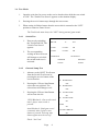
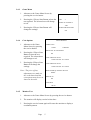
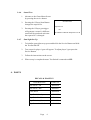
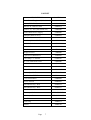
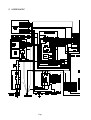
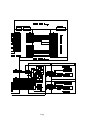
POINT BLANK
Operators Manual
Part No. 90500078
™
© 1994
Ltd - all rights reserved.
No part of this publication may be reproduced by any mechanical, photographic or electronic
process, or in the form of phonographic recording, nor may it be stored in a retrieval system,
transmitted or otherwise copied for public or private use, without permission from namco Ltd.
While the information contained in this manual is given in good faith and was accurate at the
time of publication, BRENT LEISURE LIMITED reserve the right to make changes and
alterations without notice.
No responsibility is accepted for unauthorised changes or modifications made to the machine.
Published by:
BRENT LEISURE Ltd.
Unit 1 Brent Crescent,
London. NW10 0QT
Phone:- 0181-965-0550
Fax:- 0181-961-0574
Contents
Operators Manual .............................................................................................. 1
1.
SPECIFICATIONS ..................................................................................... 4
2.
PRECAUTIONS.......................................................................................... 5
2-1
2-2
2-3
3.
Cautions When Installing. ...................................................................................... 5
Caution when Handling. ......................................................................................... 5
Cautions when Transporting. .................................................................................. 5
ADJUSTMENTS ......................................................................................... 6
3-1
3-2
3-3
3-4
Turning on the Power ............................................................................................. 6
Switches for Adjustments ....................................................................................... 6
Volume Adjust ........................................................................................................ 6
Test Mode ............................................................................................................... 7
3-4-1 Switch Test ............................................................................................... 7
3-4-2 Gun and Lamp Test .................................................................................. 7
3-4-3 Game Menu .............................................................................................. 8
3-4-4 Coin Options ............................................................................................ 8
3-4-5 Monitor Test ............................................................................................. 8
3-4-6 Sound Test ................................................................................................ 9
3-4-7 Gun Sight Set-Up ..................................................................................... 9
4.
PARTS .......................................................................................................... 9
5.
SCHEMATIC ............................................................................................ 12
1. SPECIFICATIONS
POWER SUPPLY :-
220/240volts AC
MONITOR :-
Hantarex 28" Polo Colour Monitor with auto degauss.
DIMENSIONS :-
780(w) x 900(d) x 2080(h)
WEIGHT :-
165kg.
ACCESSORIES :-
Keys:
(Cash Door) ..................... 2
(Coin Door) ...................... 2
(Back Door) ..................... 2
Hex Tamper-Proof Wrench..................... 1
IEC Mains Lead ...................................... 1
Operators Manual ................................... 1
Page 1
2. PRECAUTIONS
2-1 Cautions When Installing.
This game is designed for indoor use only. The game must not be installed outdoors or
under the following conditions:a.
In areas directly exposed to sunlight, high humidity, direct water contact, dust, high
heat or extreme cold.
b.
In locations that would present an obstacle in the case of an emergency, i.e. near
fire equipment or emergency exits.
c.
On an unstable surface or subject to floor vibration.
2-2 Caution when Handling.
a.
AC power must always be turned OFF, and the game disconnected, before
replacing any parts or connecting/disconnecting connectors.
b.
When unplugging the game from an electrical outlet, always grasp the plug, not the
mains lead.
c.
The machine must be earthed with a securely connected earthed plug.
d.
Care must be taken at all times to avoid electric shock when inspecting or
adjusting the game.
2-3 Cautions when Transporting.
a.
Do not subject the game to physical shock when transporting or moving it.
b.
Always return the levellers to the UP position before moving the machine.
c.
Take care not to rope any moulded (plastic) parts when transporting.
Page
2
3. ADJUSTMENTS
3-1 Turning on the Power
After installing the product, turn on the power. The power switch is located above the
mains inlet on the rear of the cabinet.
3-2 Switches for Adjustments
Open the front door to find the switches for adjustments.
1.
Service Switch
Press this switch to obtain game credits without incrementing the coin counter.
2.
Test Switch
Slide this switch to "ON" to enter test mode.
Test mode allows game testing and the changing of game settings.
(See "3-4 Test Mode" on page 4)
3-3 Volume Adjust
There are two volume controls, one each for left and right player. Turn the control to
increase or decrease the volumes.
SERVICE BRACKET
COIN COUNTER
VOLUME
CONTROLS
TEST SWITCH
SERVICE
SWITCH
Page
3
3-4 Test Mode
1.
Open the coin door for access to the service bracket, then slide the test switch
to "ON". The "Switch Test Screen" appears on the monitor display.
2.
Pressing the service button steps through the test screens.
3.
When testing is finished ensure that the test switch is returned to the "OFF"
position to return to Game Screen
The Test Switch must always be "OFF" during normal game mode.
3-4-1
Switch Test
SWITCH TEST
1.
2.
3-4-2
Enter test by switching
the Test Switch ON. The
"Switch Test Screen"
appears.
The corresponding
writing on the test screen
will change to red while
the switch under test is
activated.
DIP SW
12
OH
COIN1
COUNT
0H
COIN2
COUNT
0H
1P SWITCH
2P SWITCH
TRIGGER
TRIGGER
START
START
Gun and Lamp Test
1.
2.
3.
Advance to the GOUT Test Screen
from the Switch Test Screen by
pressing the service button on the
service bracket.
Pressing the 1 Player Start Button
selects the test required. The
selected test will change to red.
Pressing the 2 Player Start Button
will activate the test.
1P/2P Blowback - Gun recoils each
time 2 player start switch is
pressed
Auto Blowback - Both guns recoil
constantly when 2 player start
button is pressed. Pressing start
button again turns the test off.
Flash - Not Used
Page
4
GOUT TEST
1P
BLOWBACK
OFF
2P
BLOWBACK
OFF
1P
START LAMP
NO
2P
START LAMP
NO
FLASH
NO
AUTO BLOWBACK
NO
3-4-3
Game Menu
1.
Advance to the Game Menu Screen by
pressing the service button.
2.
Pressing the 1 Player Start Button selects the
test required. The selected test will change
to red.
GAME MENU
LIFE
3
MUSIC IN ATTRACT
YES
3.
3-4-4
Pressing the 2 Player Start Button will
change the settings.
Coin Options
1.
INITIALIZE HI SCORE
NO
COIN OPTIONS
Advance to the Game
Menu Screen by pressing
the service button.
GAME COST
1 COIN
1 CREDIT
DISCOUNT TO CONTINUE
2.
Pressing the 1 Player Start
Button selects the test
required. The selected test
will change to red.
NO
COIN 1 MECH VALUE
1 COIN COUNT AS 1 COIN
3.
Pressing the 2 Player Start
Button will change the
settings.
COIN 2 MECH VALUE
1 COIN COUNT AS 1 COIN
BONUS FOR QUANTITY BUY IN
Note:- The price of play
adjustments are made on
the credit board and the
coin options must be set as
shown in the table.
NONE
FREE PLAY
NO
COIN BOX
1 WAY
3-4-5
Monitor Test
1.
Advance to the Game Menu Screen by pressing the service button.
2.
The monitor will display vertical colour bars.
3.
Pressing the service button again will cause the monitor to display a
crosshatch pattern.
Page
5
3-4-6
Sound Test
1.
Advance to the Game Menu Screen
by pressing the service button.
2.
Pressing the 1 Player Start Button
changes the request No.
SOUND TEST
REQUEST No
3.
3-4-7
Pressing the 1 Player gun trigger
will generate a sound. A different
sound will be produced each time
the request No. is changed.
0H
LEFT/RIGHT CHECK=REQUEST No 1H
Gun Sight Set-Up
1
To initialize gun sight set-up press and hold in the Service Button and slide
the Test Switch ON.
2
Test screen for player 1 gun will appear. To adjust player 2 gun press the
Service Button.
3
Follow the instructions on the screen.
4
When set-up is completed ensure Test Switch is returned to OFF.
4. PARTS
DECALS & PLASTICS
DESCRIPTION
PART No.
Side Decal - LH
40000196
Side Decal - RH
40000197
Front Decal
40000198
Play Panel Overlay
33000022
Top Flash Vac-Form
45000196
Top Flash Acrylic
30000034
Play Instruction Card
42000003
Page
6
CABINET
DESCRIPTION
PART No.
Front Glass - Toughened (748x580x6)
31000020
Mirror (735x660x3)
31000021
Monitor 28" Hantarex Polo
84000012
Speaker 4½" 20w (with shield can)
62000006
Switch Mode Power Supply
83000040
Schaffner Mains In Assy
66000016
Schaffner Boot
66000017
Fuse 5amp 20mm Slo-Blo
63500600
Interlock Switch
60000006
Interlock Cover
39000028
Transformer
67700015
Bridge Rectifier
71000040
Capicitor 22,000mfd 25v
70200043
Fuse 3amp 1¼" Slo-Blo
63500547
18" 15w Fluorescent Tube
64500000
Choke 15w
63300000
Starter
63000000
75mm Castor
59000005
M16 Adjustable Foot
88300079
100ohm 10w W/W Potentiometer
76000164
3.5-6v Panel Meter
65000002
Service Switch
60000059
Start Button Assy - Red
60200235
Start Button Assy - Blue
60200237
Test Switch
60000023
Gun Assy - Red
XPB-GUNRED
Gun Assy - Blue
XPB-GUNBLUE
Gun Chain
45000209
Chain Clip
45000211
Holster
45000199
Page
7
5. SCHEMATIC
Page
Page