1
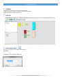
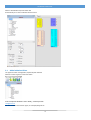
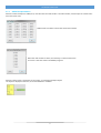
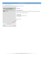
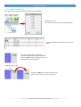
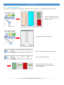
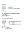
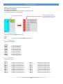
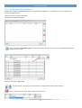
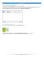
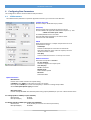
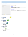
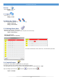
www.promax.it NS WIZARD USER GUIDE The contained information in this handbook are only informative and they can being change without warning and they must not being understandings with some engagement from Promax srl. Promax srl does not assume responsibility or obligates for errors or inaccuracies that can be found in this handbook. Except how much granted from the license, no part of this publication can be reproduced, saved in a recording system or transmitted in whatever form or with any means, electronic, mechanical or recording system or otherwise without Promax srl authorization. Any reference to names of society or products have only demonstrative scope and it does not allude to some real organization. Rev. 1.0.0 © Promax srl 2 NS WIZARD USER GUIDE 1 PREFACE This document introduce to use by nsWizard Application. NsWizard is a Promax product used with IsoNs and VTB application. NsWizard simplifies the IsoNs Applications 2 General 3 Make New Project For make a new project. Use a button “New Project or: File → New Following must be select the CNC type 3 NS WIZARD USER GUIDE Select a desired CNC and press button OK. Automatically are insert all CNC standard resources 3.1 Added a Motion Obiect The types of motion management, depend by CNC selected Select the motion type from tree view table. If the component desired is not in library, contact promax: [email protected] You can combiine more motion types, ex: CanOpen,Step/dir etc 4 NS WIZARD USER GUIDE 3.1.1 Added CanOpen Motion When the motion CanOpen is added, first, must be insert the node number. The node number, must be equal to number selected in the driver used NsWizard do not allows to select two same node numbers When the node number is select, the next step, is insert the Axis name. This name is the same used in the GCODE programs When the above steps is completed, in the project, is inserted the CanOpen object The object is displayed in the form, and can be deleted or modified 5 NS WIZARD USER GUIDE 3.1.2 CanOpen Parameters The CanOpen parameters, can be modified after the object is inserted. Select the object, with mouse, right click button Parameters: PDO Variable name You can insert the name PDO, used in the application VTB for a interpolated value. Is not necessary change the PDO name Node Number You can change the node number Click on button Click on button 6 NS WIZARD USER GUIDE 3.1.3 Added Pulse/Dir Motion This motion type, is used only if the CNC support the axes STEP/DIR Insert the Axis name. This name is the same used in the GCODE programs Insert the STEP/DIR channel where is connect the motion This motion tipology has not properties. Is possible change only the channel STEP/DIR Select the STEP field with left button mouse, and drag and drop in the new channel Left Button Mouse Click For drag the FIELD, press and do not release left button mouse, until it is on the new channel 7 NS WIZARD USER GUIDE 3.1.4 Added PID +/-10V Motion For insert this motion type, the CNC must have, the encoder channel and analog +/- 10 Volt outputs (ex: NGIO for NG35) First insert a expansion board ex: NGIO (2 encoder inputs, 2 analog outputs +/-10V) Select PID type, and axis name to used. Select the encoder channel and analog output The axis is automatically added Also this motion type, has not property. Is possible change the channel, in the same mode to STEP/DIR 8 NS WIZARD USER GUIDE 3.2 Added Expansions Board Is possible added the expansion boards in two tipology: 1. On local bus 2. On CanOpen field bus Select a expansion board. Automatically all hardware resources are added at the project. The expansion boards on local bus, are automatically enumerate. For the expansion boards on field bus, is requested the node number 3.3 Added the external components On the Inputs and outputs, is possible inserting the external components: Buttons, Touch probe, Homing switch, Limits switch, Override potentiometer, Manual jog etc. 3.4 Digital Inputs Class This class contains all digital inputs management by CNC. All digital inputs have only one property: N.O. (contact normally open) N.C. (contact normally close) 3.4.1 Buttons Contains all buttons type which can be connect on the CNC Select the components and insert it in the digital inputs on the CNC Buttons available: EMCY → Emergency button START → External START button START-STOP → START/STOP Button If CNC in STOP, is required a START If CNC in START is required a STOP STOP → STOP button PAUSE → PAUSE button 9 NS WIZARD USER GUIDE When the button is inserted, is possible change the property: N.O. (contact normally open) N.C. (contact normally close) By Drag and Drop is possible move the button, in a digital input free For change the property see following step: Click in the check box with left mouse button for change the input type (N.O. - N.C.) Click right mouse button 3.4.2 Touch Probe Input Probe input used during G102 Gcode function Probe: ACQ 3.4.3 → Probe input used during G102 Gcode function Homing Inputs Switch for homing inputs Homing: HomeX HomeY HomeZ HomeA HomeB HomeC HomeU HomeV HomeW 3.4.4 → Input Homing Axis X → Input Homing Axis Y → Input Homing Axis Z → Input Homing Axis A → Input Homing Axis B → Input Homing Axis C → Input Homing Axis U → Input Homing Axis V → Input Homing Axis W Limits Switch Switch for Axes limits Switch: FCM_X FCM_Y FCM_Z FCM_A FCM_B FCM_C FCM_U FCM_V FCM_W → Negative Limit Switch Axis → Negative Limit Switch Axis → Negative Limit Switch Axis → Negative Limit Switch Axis → Negative Limit Switch Axis → Negative Limit Switch Axis → Negative Limit Switch Axis → Negative Limit Switch Axis → Negative Limit Switch Axis X Y Z A B C U V W FCP_X FCP_Y FCP_Z FCP_A FCP_B FCP_C FCP_U FCP_V FCP_W 10 → Positive Limit Switch Axis → Positive Limit Switch Axis → Positive Limit Switch Axis → Positive Limit Switch Axis → Positive Limit Switch Axis → Positive Limit Switch Axis → Positive Limit Switch Axis → Positive Limit Switch Axis → Positive Limit Switch Axis X Y Z A B C U V W NS WIZARD USER GUIDE 3.4.5 Single JOG Axis Manual JOG for single Axis. JOG: JOGP_X JOGP_Y JOGP_Z JOGP_A JOGP_B JOGP_C JOGP_U JOGP_V JOGP_W 3.4.6 → Positive JOG Axis X → Positive JOG Axis Y → Positive JOG Axis Z → Positive JOG Axis A → Positive JOG Axis B → Positive JOG Axis C → Positive JOG Axis U → Positive JOG Axis V → Positive JOG Axis W JOGM_X JOGM_Y JOGM_Z JOGM_A JOGM_B JOGM_C JOGM_U JOGM_V JOGM_W → Negative JOG Axis X → Negative JOG Axis Y → Negative JOG Axis Z → Negative JOG Axis A → Negative JOG Axis B → Negative JOG Axis C → Negative JOG Axis U → Negative JOG Axis V → Negative JOG Axis W Selector JOG Axes Jog Axes by selector . Only one axis at a time can be selected JOG: JOGP JOGM SELX SELY SELZ SELA SELB SELC SELU SELV SELW 3.5 → Positive JOG Axis selected → Negative JOG Axis selected → Digital Input Select Axis X → Digital Input Select Axis Y → Digital Input Select Axis Z → Digital Input Select Axis A → Digital Input Select Axis B → Digital Input Select Axis C → Digital Input Select Axis U → Digital Input Select Axis V → Digital Input Select Axis W Analog Inputs Class This class contains all analog inputs available 3.5.1 Feed Control A questa classe di componenti esterni, fanno parte gli ingressi analogici per il controllo della FEED Assi (es potenziometro di overide). Analog: OW% → FEED Override potentiometer 11 NS WIZARD USER GUIDE 3.6 Digital Output Class This class contains all digital outputs on CNC You can changed only one property: N.O. (contact normally open) N.C. (contact normally close) About the properties management see chapr. 3.4 3.6.1 Signals This class contains all CNC signals Signals: ALARM CNREADY CNSTOP CNRUN CNSTOPRUN CNPAUSE 3.7 → Active when the CNC is on Alarm → Active when the CNC is ready to work (when the VTB application is started) → Active when the CNC is in STOP → Active when the CNC is in RUN (Gcode executing) → Active when the CNC is in RUN, Deactive when the CNC is in STOP → Active when the CNC is in PAUSE Encoder Class This class contains the electronic handweel. This have not some property 3.7.1 HandWeel Handweel for manual JOG Axes The axis movmented by HandWell, is the Axis Selected for JOG HandWell: VOL_AXIS 3.8 → Object to insert in the free encoder channel. Class M Functions on CNC A questa classe sono associate tutte le funzioni M gestite dal CNC. Tipo M3 , M4 ecc. 3.8.1 M3 - M4 -M5 Spindle management: M3 → Start Spindle CW M4 → Start Spindle CCW M5 → Stop Spindle Is inserted, a “M3-M4-M5 MACRO”. It must be configured for a correct Spindle Management 12 NS WIZARD USER GUIDE 3.8.2 M3-M4-M5 Configure by NsWizard NsWizard can configure the M3,M4,M5 functions. If the NsWizard configuration is not sufficient, you can configure the M function by VTB Application. Select the function by right mouse button Following this window is displayed: Click on the button “Insert New Output” and choose the digital output (one or more) to activated/deactivated when the M function is called: Select teh output state OFF or ON Use these buttons, for move Up or move Down the activated/deactivated outputs sequence Use this button for delete select digital output in the M function 13 NS WIZARD USER GUIDE 3.8.3 SPEED10V Spindle 0-10V speed This component, allow to set the Spindle Speed by 0-10 V analog output The Spindle Speed is set by S Gcode function. For adapting the Speed, you must set the MAX_SPEED_SPINDLE IsoNs parameter. It indicate the Rpm at 10 Volt analog output. (see Chapr 4 “Configuring Base Parameters”) This component must be inserted in analog output (you must insert the boards: NGIO, NGQx etc.) 3.8.4 MODBUS Spindle Speed This component, allow to set the Spindle Speed by Modbus RTU protocol For Modbus register configuration, see the Chapr. 4 “Configuring Base Parameters” The ModBus serial data output, is ever refered to SER2 on CNC (it can be configured RS232 or RS485) 14 NS WIZARD USER GUIDE 4 Configuring Base Parameters This configuration allow to set the IsoNS and VTB parameters 4.1 VTB Parameters The VTB Parameters, defined an important application functions, you must set it with attention CanOpen baud rate Set the CanOpen Baud Rate only if present. TAU (msec) System Sample CNC (see following reference values) From 1 to 5 Msec for application with Axes Canopen or +/- 10V. 2 Msec can control up to 8 Axes For PULSE/DIR Axes from 2 to 5 Msec Check by VTB Debug Application, the Task Plc Load. It should not be over the 80% CFGTO START UP parameters for CanOpen components in the line Is prefered not change N. Attempts Number of Attempts for connection to Slave Node. After these Attempts, if the node not respond, the error: “Node not found” is called Time (Ms) Time in millisecond between an attempt and another Modbus Parameters Parameters for Spindle in MODBUS Nr. Freq. Register Number of register for Frequency Set Time Out (ms) ModBus Time Out ModBus node Node modbus Spindle Baud rate Select Baud Rate Spinlde Parameters Max Divisions Indicate the number of division for Speed setting If SPED10V insert 2048 for a 10V value (normally not change) If the Spinlde is ModBus, the value is the frequency in Hertz for a setting the Rpm Max See the Max Speed Spindle (rpm) parameter Max Speed (rpm) Indicate the Spindle RPM max refered top 10V analog output (SPED10V) or rpm max refered at Hertz value Ex: Analog Spinlde at 18000 rpm (uses SPED10V) Max Divisions 2048 Max Speed (Rpm) 18000 Ex: Modbus Spinlde at 18000 rpm at 50Hz (uses MODBUS) Max Divisions 50 (or 500 you must see the inverter parameters) Max Speed (Rpm) 18000 15 NS WIZARD USER GUIDE 4.2 IsoNs Parameters There are not particulars parameters to set in IsoNs, NsWizard can generate automatically the file “IsoNs.cfg” Generate IsoNs configuration Check for generate IsoNs.cfg IsoNs folder If enabled the above parameter, and enabled this parameter, the IsoNs.cfg file, is generate in the IsoNs folder (if it is installed) WARNING The actual file IsoNs.cfg, will lost Destination folder If not enabled the parameter “IsoNs Folder”, you can choose the folder where will saved the new file Isons.cfg 5 Load Project Allow to load a project previously saved in hard disk File → Open 6 Save project Save the actual project File → Save 7 Save As Save the actual project with name File → Save As 8 Print Print the connections list File → Print 9 Export Export the connections list in the CSV file File → Export 16 NS WIZARD USER GUIDE 10 Cut Delete the selected obkect Modify → Cut 11 Undo Cancel the last modify Modify → Undo 12 Move Up - Down Move the selected object Up or Down on the drawing Modify → Move Up Modify → Move Down 13 Defining Gantry Axes Defines the gantry Axes in the project The Gantry axis, pratically, is a copy of other axis (the same movement) Project → Axes Gantry Select the Gantry Axes Ex: X (master) Gantry with A (slave) The other combinations with X and A axes, are automatically exluded 14 Compile Project Compiles the actual project and generates the VTB Project. If the actual project, has not been saved, the new saving is proposal. The VTB project, will have the same name of the NsWizard Project, but with extension “.pxp” Open the .Pxp project with VTB , compile it and upload on the CNC Project → Compile 17 NS WIZARD USER GUIDE Index 1 PREFACE .................................................................................................................................................. 3 2 General ....................................................................................................................................................... 3 3 Make New Project...................................................................................................................................... 3 3.1 Added a Motion Obiect ....................................................................................................................... 4 3.1.1 Added CanOpen Motion .............................................................................................................. 5 3.1.2 CanOpen Parameters .................................................................................................................... 6 3.1.3 Added Pulse/Dir Motion .............................................................................................................. 7 3.1.4 Added PID +/-10V Motion ......................................................................................................... 8 3.2 Added Expansions Board .................................................................................................................... 9 3.3 Added the external components .......................................................................................................... 9 3.4 Digital Inputs Class ............................................................................................................................. 9 3.4.1 Buttons ......................................................................................................................................... 9 3.4.2 Touch Probe Input ...................................................................................................................... 10 3.4.3 Homing Inputs ........................................................................................................................... 10 3.4.4 Limits Switch ............................................................................................................................. 10 3.4.5 Single JOG Axis......................................................................................................................... 11 3.4.6 Selector JOG Axes ..................................................................................................................... 11 3.5 Analog Inputs Class .......................................................................................................................... 11 3.5.1 3.6 Digital Output Class .......................................................................................................................... 12 3.6.1 3.7 4 Signals ........................................................................................................................................ 12 Encoder Class .................................................................................................................................... 12 3.7.1 3.8 Feed Control............................................................................................................................... 11 HandWeel ................................................................................................................................... 12 Class M Functions on CNC............................................................................................................... 12 3.8.1 M3 - M4 -M5 ............................................................................................................................. 12 3.8.2 M3-M4-M5 Configure by NsWizard ......................................................................................... 13 3.8.3 SPEED10V Spindle 0-10V speed .............................................................................................. 14 3.8.4 MODBUS Spindle Speed .......................................................................................................... 14 Configuring Base Parameters .................................................................................................................. 15 4.1 VTB Parameters ................................................................................................................................ 15 4.2 IsoNs Parameters ............................................................................................................................... 16 5 Load Project ............................................................................................................................................. 16 6 Save project .............................................................................................................................................. 16 7 Save As..................................................................................................................................................... 16 8 Print .......................................................................................................................................................... 16 18 NS WIZARD USER GUIDE 9 Export....................................................................................................................................................... 16 10 Cut ............................................................................................................................................................ 17 11 Undo......................................................................................................................................................... 17 12 Move Up - Down ..................................................................................................................................... 17 13 Defining Gantry Axes .............................................................................................................................. 17 14 Compile Project ....................................................................................................................................... 17 19