1
www.promax.it
VTB USER GUIDE
The information contained in this document are for informational purposes only and are subject to change without notice
and should not be interpreted by any commitment by Promax srl. Promax Ltd. assumes no responsibility or liability for
errori or inaccuracies that may be found in this manual. Except as permitted by the license, no part of this publication may
be reproduced, stored in a retrieval system or transmitted in any form or by any means, electronic, mechanical, recording
or otherwise without prior permission Promax srl.
Any references to company names and products are for demonstration purposes only and does not allude to any actual
organization.
Rev. 3.00.0
2
VTB USER GUIDE
1
INTRODUCTION
VTB is an integrated development environment for OBJECT oriented programming on PROMAX platforms. This
environment contains inside all tools needed to development of application in simple and intuitive way. The VTB
philosophy is based on latest technologies R.A.D. (RAPID APPLICATION DEVELOPMENT) which allow a fast
development of application writing a reduced amount of source code. A large library of OBJECTS and TECNHOLOGIC
FUNCTIONS allow to create applications for all sector area of industrial automation. VTB integrates a high level
language like enhanced BASIC MOTION. It's also possible to manage in clear and simple way FIELD BUS such as:
CAN OPEN
ETHERCAT
MODBUS
Powerful functions of AXIS MOVING allow to manage any type of machine using LINEAR, CIRCULAR, FAST LINEAR
INTERPOLATION or ELECTRIC GEAR, CAM PROFILES, etc.
VTB is predisposed for MULTI-LANGUAGE APPLICATIONS simply selecting the USING LANGUAGE.
2
NOTES ON PROGRAMMING LANGUAGE
VTB programming language is defined as BASIC MOTION.
Its syntax is very similar as enhanced BASIC with some terminologies derived from C language. Management of the
functions is very similar as VISUAL BASIC also for DATA STRUCTURES.
Some INSTRUCTIONS are VTB PROPRIETARY but following the same philosophy.
VTB is a language CASE INSENSITIVE that is it make no differences between UPPER CASE and LOWER CASE regarding
instructions, functions, variables etc. VTB converts internally all characters in UPPER CASE. The only one exception is
the management of DEFINE where characters are not converted in upper case but they remain so in all compilation
passes.
Because VTB is a language addressed to MOTION, some features, considered of secondary importance, remained at
PRIMITIVE level. For example the STRING management is made like C language using function such as STRCPY, STRCAT,
STRCMP etc.
3
VTB USER GUIDE
3
DEVELOPMENT ENVIRONMENT
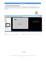
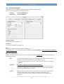
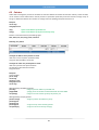
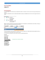
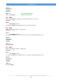
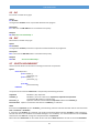
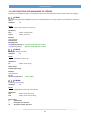
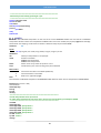
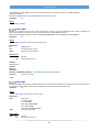
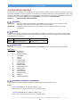
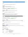
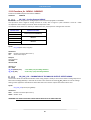
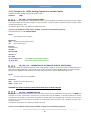
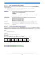
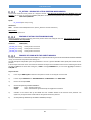
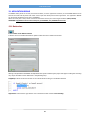
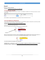
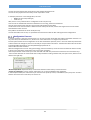
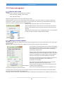
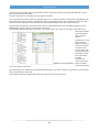
The development environment of VTB has an common intuitive interface like all Windows applications. It isn't
necessary to have a great experience of programming. In the environment is included an EDITOR optimized for VTB
programming.
GRAPHIC/TEXT window
switching button
TREE VIEW
PROJECT
MANAGER
Graphic window
TOOLBAR
4
VTB USER GUIDE
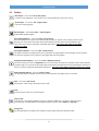
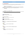
3.1 Toolbar
New Project - From menu File → New project
It creates a new application. The previous one is closed requesting a confirm for saving.
Open Project - From menu File → Open project
It opens an existing project.
Save Project - From menu File → Save project
It saves the current project
Copy Selected Object/s - From menu Edit → Copy (Ctrl+C)
The selected objects are copied in the clipboard. All property are copied, also the object position inside
the page. The name of the new object will be automatically set with the first name avalaible for that
class. It works as common copy/paste of Windows applications. The source code added to the object
events isn't copied.
Paste Copied Object/s - From menu Edit → Paste (Ctrl+V)
The objects copied in the clipboard are pase. All property of original objects are unchanged, also the position.
The function Cpy/Paste is very useful to create pages with the same objects.
Duplicate Selected Object/s - From menu Edit → Duplicate (Ctrl+D)
This works exactly the same as Copy/Paste but on one command. All property are copied, also the object position
inside the page. The name of the new object will be automatically set with the first name avalaible for that class. It
works as common copy/paste of Windows applications. The source code added to the object events isn't copied.
Delete Selected Object/s - From menu Edit → Delete
The selected objects is deleted. Also the source code included in the object events is removed.
Find - From menu Edit → Find
Searching for a text string in the project source code.
Print
It prints the text code in the current window.
Snap to Grid
If this button is activated the OBJECTS position is hooked to GRID step. It is useful to align the object
quick and easy. The GRID STEP can be changed in PIXEL units from menu Options -> Grid Step.
Foreground
The selected objects is brought to the foreground of the page making it completely visible.
5
VTB USER GUIDE
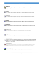
Background
The selected objects is brought to the background of the page. It can be covered by other
objects making it invisible.
Align left
The selected objects are aligned to left margin. The reference object will be the last selected.
Align right
The selected objects are aligned to right margin. The reference object will be the last selected.
Align top
The selected objects are aligned to top margin. The reference object will be the last selected.
Align bottom
The selected objects are aligned to bottom margin. The reference object will be the last selected.
Align horizontal
The selected objects are aligned at the horizontal center of the last selected object.
Align vertical
The selected objects are aligned at the vertical center of the last selected object.
Program compiling
The entire application is compiled to create the binary file in the format of the platform selected. The
compiling results are showed in the MESSAGE WINDOW and if there are some compiling errors the
binary file will not be created.
Transfer Program
The binary file created by compiler is transferred to the control by RS232 or ETHERNET line. The
program will be saved in the permanent memory of the control and then it will be executed.
CanOpen Configurator
It launches the CanOpen configuration tool (see chapter CANOPEN CONFIGURATOR).
6
VTB USER GUIDE
EtherCAT Configurator
It launches the EtherCAT configuration tool (see chapter ETHERCAT CONFIGURATOR).
DEBUG
It launches the DEBUG tool (see chapter DEBUG APPLICATION).
7
VTB USER GUIDE
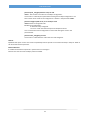
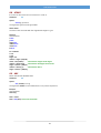
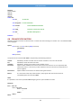
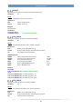
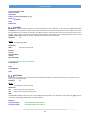
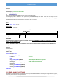
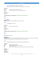
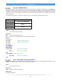
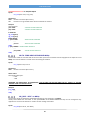
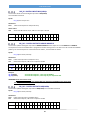
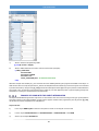
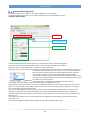
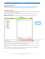
3.2 Project Manager
The PROJECT MANAGER allows a fast selection and navigation in all the PAGES of the PROJECT. From this AREA we
have the entire control of the application: viewing pages, managing of variables, writing code, etc.
New Page - From menu Pages → New
It adds a new page to the project. The page is automatically numbered. A page can contain GRAPHIC
OBJECTS and source code. Both will work only when the page will be loaded and only a page at time can
be loaded. To switch from a page to another can be used the system function:
Pagina(NrPag)
Delete Page - From menu Pages → Delete
It deletes the showed PAGE. The entire content will be lost and all the page after this will be renumbered.
Attention: all reference to these pages (button of function) will have to be modified.
View Graphic of the Page
It shows the graphic window of the page.
View Code of the Page
It shows the source code editor window of the page.
View Variables of the Page
It shows the table of private variable of the page.
View GLOBAL Variables and STRUCTURE definitions
View source code editor of TASK PLC
View source code editor of TASK MAIN or TASK TIME
View source code editor of a page
8
VTB USER GUIDE
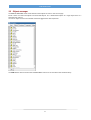
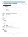
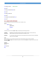
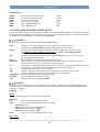
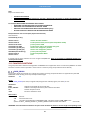
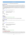
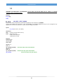
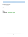
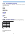
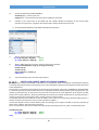
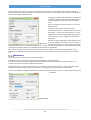
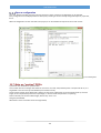
3.3 Objects manager
The OBJECTS MANAGER allows a fast selection of the objects to insert in the current page.
Inside it there are both base-objects and enhanced-objects. For a detailed description of a single object there is a
separated user manual.
To insert an object it have to be selected and then dragged to the desired position.
The LOAD button allows to browse the CUSTOM OBJECT which are not included in the standard library.
9
VTB USER GUIDE
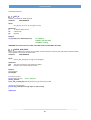
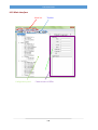
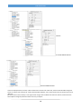
3.4 Functions Manager
In this Tree View are showed all the STRUCTURE and FUNCTIONS grouped per page. Just open the nodes to view
informations.
In STRUCTURE section there is the possibility to add a new one by add-element button, it is also possible to remove
the selected structure by delete-element button.
Opening an existent structure the fields of it are showed. By a click on the single field it is possible to modify its type,
while the buttons add-element and remove-element can be used to add o remove a field from the structure.
The section FUNCTIONS groups the functions per page, selecting a single function the editor window is opened
showing the relative source code.
3.5 Objects Property
In the area OBJECTS PROPERTY it's possible to set all the working properties of an OBJECT. Properties are proprietary
of the single object, refer to relative user manual for details.
To set a property click with the left button of the mouse on the desired item and put the new value. To show the
properties the object has to be selected before.
LIST OF THE PAGE'S OBJECTS
To simplify the selection of the OBJECT INCLUDED IN THE PAGE can be useful the COMBO-MENU clicking on the name
of the desired object.
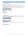
3.6 Text Table Manager
OBSOLETE SECTION
10
VTB USER GUIDE
4
CONFIGURATION OF VTB
From Menu
Tools Options
This command is used to configure some options of the VTB environment and the target hardware.
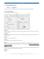
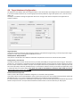
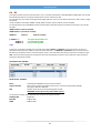
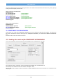
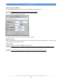
4.1 General Options
This table contains the general options of VTB
View Grid
When this check-box is activated the grid on the page windows is displayed. The grid is useful as referenc to position
the graphic objects.
Snap to Grid
Activating this check-box the snap to grid is enabled. The objects will be positioned to the grid simplifying the manual
alignment of them.
Grid Step
It sets the number of pixel of the grid step.
Start Page
It selects the number of the first page to be loaded at start-up.
Sample
It selects the scan time of the TASK PLC (see chapter 5) in milliseconds. It can be changed with the resolution of 0.1
millisecond being careful at low value because they can cause crash of the program. Always examine the elapsed time
of TASK PLC by the DEBUG.
Task time
It is the scan time of the TASK TIME in multiples of TASK PLC scans, the resultant time (in milliseconds) is displayed on
the right. Changing the time of TASK PLC this time changes too.
Savescreen
OBSOLETE
11
VTB USER GUIDE
Standard Mode
OBSOLETE
Debug Mode
OBSOLETE
Debug Standard
OBSOLETE
Debug.NET
It forces the use of the new DEBUG.NET application. On PC must be installed the Framework 2.0 or major.
This is the debug option recommended.
Warning Level
Level 0 Compiler doesn't display any warning messages.
Level 1 Compiler displays warning messages when improper or dubious operations on
variables are found. Anyway the binary file is created.
4.2 RS232 Protocol
(OBSOLETE)
12
VTB USER GUIDE
4.3 Field-Bus Protocol
These options allow to select the Field-Bus protocols used by the target hardware.
For the moment the protocols implemented are two:
CanOpen
Ethercat CoE
Standard DS301 DS4xxx
(Can Over Ethercat)
CanOpen Protocol
It enables the CanOpen protocol.
BaudRate
It selects the BaudRate of CanOpen line.
Sync
It enables or disables the SYNC message on CanOpen line.
The message Sync is sent cyclically at the time of TASK PLC (set in General Options). SYNC is essential for applications
with AXIS INTERPOLATED
Chek Error Showing mode
It selects the display mode of the eventual errors during the CanOpen configuration (see CanOpen configurator),
there are three option:
None
On systems with display the result of configuration of each node is showed then the
application continue indipendently there have been error or not.
On systemes without display there isn't any indication of eventual errors of CanOpen
configuration.
Standard
This option is valid only on systems with human interface.
A specific object (CanErr) is added on MAIN page wich displays the list of node with
the result of configuration. If there have been any errors program stops waiting for
the press of a specific button to continue.
Custom
With this option the system doesn't perform any action but it calls some functions to
allow the customization of the managing of CanOpen configuration errors.
The functions called by the system are three and they have to be defined by the
application:
13
VTB USER GUIDE
function open_cancfgerr(nodes as char) as void
nodes = Total number of nodes in the CanOpen configuration.
This function is called by the system before starting the CanOpen configuration. The
total number of the nodes in the configuration is written in the parameter nodes.
function cancfgerr(nodo as int, err as uchar) as void
nodo=Number of configured node.
err=Result of configuration.
0 = Node correctly configured.
<>0 = Error code. See relative chapter of CanOpen functions.
This is called at the end of configuration of each node writing the result in the
parameter err.
function close_cancfgerr() as void
This function is called after the end of the last node configured.
Slow Px
By default this option is set to one but for compatibility with all systems we recommend to keep it always at ZERO. It
will be used for future expansions.
Ethercat Protocol
It enables the the Ethercat protocol in system which can manage it.
Ethercat can work also with CanOpen protocol enabled.
14
VTB USER GUIDE
4.4 Target Hardware Configuration
An application must always refer to the target hardware. That allows VTB to preconfigure for the selected hardware so
it can use the relative function-call, use the appropriate memory addresses, signal the specific errors, use the correct
debug, etc.
Normally it is set before starting the application but we can change it ever after to adapt the same application at
another hardware.
Target Hardware
This Combo allows to choose the code of target hardware. To facilitate the programming, in the list, beyond the single
products, are also some preconfigured combinations such as:
NGM13/LPC20 – NG35/LPC40 etc.
They refer to a combination of a NGM13 or NG35 CPU coupled with a Promax serial terminal LPC20, LPC40.
Saving memory reserved area
This option selects the amount of internal memory reserved (called IMS) to the application data saving (ex. Parameters,
recipes, etc.). This memory is organized in blocks of 256 bytes therefore it must select the number of blocks to reserve
for each recipes and the max number of recipes. For example if the memory needed for one recipe is 300 byte, we must
set 2 blocks (512 byte). Normally the IMS memory is removed from the flash memory reserved to the application, keep
in mind that when you set this option. This option isn't valid for the hardware in which the CODE FLASH isn't shared
with the data saving memory (ex. NGM13).
Create framework component
VTB can create a DLL Component Model to integrate in a Framework .NET application.
That allows a direct control of the Hardware resource from external Host such as PC equipped with operative system like
Windows XP, Vista, 7, CE or other supporting Framework (see Framework Component chapter ).
If create framework component is checked the component type must be choose (Windows Xp or Windows CE) and also
the DLL component name. A component framework file will be create in the same directory of VTB project.
15
VTB USER GUIDE
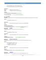
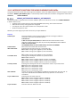
5
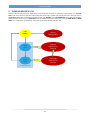
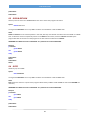
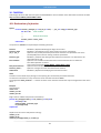
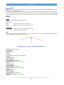
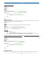
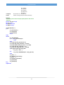
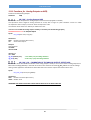
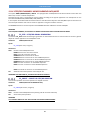
TASKS MANAGED BY VTB
VTB provides the programmer for TASKS wich can be combined to create an application. Two of these are interrupt
tasks, that means they are executed, interrupting the other tasks, at fixed and constant time; the other two task in
cooperative mode: they are executed one after another. The TASK PLC is the DETERMINISTIC task at highest level witch
interrupts all the other tasks, the TASK TIME works like TASK PLC but with a lower level, finally the PAGE TASK and MAIN
TASK run in cooperative mode between them and can be interrupted by the other two.
VTB
KERNEL
Service
Management
MAIN
Code
TASK PLC
High Priority
Interrupt
PAGE
Code
TASK TIME
LOW Priority
Interrupt
Cooperative Task
16
VTB USER GUIDE
5.1 Task Plc
This task is the higest priority one: it is deterministic and run at fixed time making it suitable to manage situation that
need a fast and precise response time. This task can not be interrupted by no other tasks but it can instead interrupt any
other. Normally it is used by AXIS CONTROL OBJECTS or fast PLC cycles, but it can contain every type of code sequence
exluding some IFS functions like:
GRAPHICS FUNCTIONS
AXIS INTERPOLATION (xxx.MOVETO, xxx.LINE_TO)
MANAGE OF CANOPEN SDO.
STATIC CYCLES
(see the single functions for details)
The typical sample time is 2 milliseconds wich is an enough time to manage a lot of application (for example 6 AXIS
interpolation), however it can go down also under 1 millisecond when the charge of work is less stressful and for CPU
with high computing power. In this task is also managed the CAN OPEN and ETHERCAT protocol in DETERMINISTIC mode.
However it is advisable that its elapsed time doesn't exceed 60% of sample time, else we risk to slow or even to stop
the other tasks. The TASK PLC HASN'T A SECTION TO INSERT ANY OBJECT, therefore if there is some code wich have to
run inside, it must be written at the moment of object design. IF THE CODE INSIDE TASK PLC BLOCKS IT ALL SYSTEM GO
IN CRASH.
To verify the elapsed time of TASK PLC there are two field in DEBUG.NET application:
PLC TP and PLC TM never must exceed the sample time.
VTB defines some
NOTE ON CONCURRENT PROGRAMMING
The use of CONCURRENT programming requires particular WARNING as in all MULTITASK systems. To avoid unexpected
operation it's recommended do not call the same function from INTERRUPT TASKS and COOPERATIVE TASK in the same
application. In other words the functions managed by MAIN TASK can be called without problems from PAGE TASK, but
NOT ALSO from TASK TIME e TASK PLC and vice versa.
That is because if an INTERRUPT TASK using a function occurs exactly while a COOPERATIVE TASK is running in the same
function, that could lead to abnormal operations in the application.
SHARING OF VARIABLES
Again in CONCURRENT programming can also occur some problem when variables are shared between INTERRUPT
TASKS and COOPERATIVE TASK. Practically if managing of the variable don't provide an ATOMIC ASSEMBLER
INSTRUCTION, this can cause false reading value when it is written by a TASK and read by another. According to the CPU
type of the system these problems can occur in the following type of variables:
Sistem
Variable type
32 bit
FLOAT
To overcome this problem VTB offers the possibility of a SECURE SHARING OF VARIABLES. Indeed in the variables
declaration dialog there is an apposite field to enable the secure sharing. However, because a lot of use of this facility
can generate jitter problem we recommend to use the enable of secure sharing of variables only when ABSOLUTELY
NECESSARY.
The same problem could also occur when using data array shared by more process. A simple example can be the use of
array to data exchange in MODBUS protocol. These problems can arise when, for example, the writing process of data
and the reading one are asynchronous. It can happen indeed that a reading process starts when the writing one has
filled the array only partially. In this case the reading process will read a lot of new data and some from the old scan. It's
evident in this situation false value readings can occur. System isn't able to understand these situations therefore to
solve it there is the needs of semaphores at application level.
Task plc has also an INIT section. All code insert here will run only one time at system reset.
17
VTB USER GUIDE
5.2 Task Time
TASK TIME, like TASK PLC, works at fixed time. It deffers from that for two features:
a) it has a lower priprity and it can be INTERRUPTED by TASK PLC;
b) it hasn't limit to managing of the IFS functions of VTB.
The scan time of this task is programmable at multiple of the sampling time of TASK PLC. TASK TIME is useful for the
managing of timed cycles and with medium response time, furthermore the possibility of calling all IFS functions makes
it of great utility, ensuring constant time to software. Typical sample time can be about 5 or 10 milliseconds, with witch
it's possible to manage a complex PLC cycle with a lot of I/O channels. If the elapsed time of this task overcomes its
sample time the system will continue to work stopping the cooperative tasks but task plc will continue to run.
TASK TIME HAS A SECTION TO INSERT THE OBJECT, therefore all the object inserted inside will run in this task at the
programmed SAMPLING TIME.
5.3 Task Main
TASK MAIN is called continuously by VTB cycle running in COOPERATIVE mode with PAGE TASK. Therefore a static cycle
on TASK MAIN will stop the PAGE TASK and vice versa. Its scanning time depends by the code contained in all the other
TASKS. Usually this TASK manages repetitive cycles as control of emergency or alarm states, graphic control etc. where
there isn't the need for constant time. However its scanning time can be very fast, also in the order of few microseconds,
when the code inside the task is very short.
TASK MAIN HAS A SECTION TO INSERT THE OBJECTS, therefore all the object inserted inside will run in COOPERATIVE
mode and regardless of which page is displayed.
TASK MAIN provides three sections to insert the CODE:
INIT PAGE
MASTER CYCLE
PAGE FUNCTIONS
Also there is a section MASTER EVENT but it has been left only for compatibility with older versions and therefore it
must not be used.
INIT PAGE
The code in this section runs only one time at the start of the program and usually it handles the initialization of the
global variables in the application. In this section we can write any type of code as long as it isn't STATIC CODE which
can block the program.
MASTER CYCLE
This is the cyclic section called by system in cooperative mode with PAGE TASK.
PAGE FUNCTIONS
This section is the container for all the functions used by the application. They will be visible GLOBALLY from all TASKS
5.4 Page Task
PAGE TASK works like TASK MAIN, with which shares the scanning time in COOPERATIVE mode. The peculiarity of this
task is its code will be loaded only when the page is running. The IFS function pagina(n) allows to run the page, written
before with VTB environment, destroying the previous one. PAGES have to be seen as a set of code-graphics managed
at convenience. Commonly PAGE TASKS are useful in systems equipped with HMI pages where they are both graphics
part and associated code. In systems without HMI, pages are only part of code which runs when commended by
pagina(n) function. As for TASK MAIN the scan time depends by the length of code inside all the other tasks. Usually the
PAGE TASK manages cycles of setting, preparing and display of data application, with control of the graphics and data
input.
PAGE TASK HAS A SECTION TO INSERT THE OBJECTS, therefore all the object inserted inside will run in COOPERATIVE
mode and regardless of which page is displayed.
PAGE TASK provides three sections to insert the CODE:
INIT PAGE
MASTER CYCLE
PAGE FUNCTIONS
18
VTB USER GUIDE
Also there is a section MASTER EVENT but it has been left only for compatibility with older versions and therefore it
must not be used.
INIT PAGE
The code in this section runs only one time at the start of the program and usually it handles the initialization of the
global variables in the application. In this section we can write any type of code as long as it isn't STATIC CODE which
can block the program.
MASTER CYCLE
This is the cyclic section called by system in cooperative mode with PAGE TASK.
PAGE FUNCTIONS
This section is the container for all the functions used by the application. They will not be visible from all TASKS.
19
VTB USER GUIDE
6
VARIABLES TYPE
VTB can manage several types of variables which can be used in programming phase.
Commonly all VARIABLES will be allocated in the VOLATILE MEMORY (RAM) of the system and they are zeroed at reset.
In systems equipped with NON-VOLATILE RAM (as NG35 or PEC70) it's also possible to allocate them in this area, they
are defined as STATIC VAR and they will retain its value also after turn-off. VARIABLES follow the STANDARD terminology
similar to common programming languages.
Furthermore it can be declared VARIABLES referred to external component like CANOPEN or ETHERCAT configurator.
These are managed automatically from the system in transparent mode.
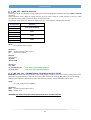
6.1 Numeric Values
VTB manages numeric values in conventional mode as other compilators. A numeric value can be written in DECIMAL
NOTATION as well as in HEXADECIMAL NOTATION by preceding the number with the prefix 0x (ZERO X). For example
the decimal number 65535 is translated with the hexadecimal 0xFFFF.
FLOATING-POINT values must be written with decimal point and it can not written in hexadecimal format.
Example:
A=1236
A=0x4d
B=1.236
‘ assigning 1236 to variable A
‘ assigning hexadecimal value 0x4d to variable A
‘ corresponding at decimal value 77
‘ assigning floating-point value 1.236 to variable B
20
VTB USER GUIDE
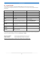
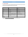
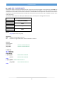
6.2 Internal Variable
These variables are allocated in the VOLATILE MEMORY (RAM) of the system and are zeroed at reset.
The possible types managed by VTB reflects the main types defined in a lot of programming languages and they are
the following:
TYPE
DIMENSION
RANGE
BIT
1 bit
From 0 to 1
CHAR
8 bit signed
From –128 to +127
UCHAR
8 bit unsigned
From 0 to 255
INT
16 bit signed
From –32.768 to +32.767
UINT
16 bit unsigned
From 0 to 65.535
LONG
32 bit signed
From –2.147.483.648
to +2.147.483.647
FLOAT
64 bit (standard DOUBLE format IEEE 75)
From -1,79769313486232e308
to +1,79769313486232e308
STRING
Supported only as constant
VETTORE
Single dimension for all variable types
except BIT type
STRUCTURE
Standard declaration
POINTER
Char, Uchar, Int, Uint, Long, Float
32 bit
DELEGATE
Pointer to FUNCTIONS
32 bit
It's appropriate using variables according to the minimum an maximum value they have to contain choosing the best
appropriate. INTERNAL VARIABLES can be declared PAGE LOCAL or GLOBAL.
PAGE LOCAL VARIABLES
declared inside the PAGE TASK and visible only to it
GLOBAL VARIABLES
declare in MAIN TASK and visible to all the others
VTB doesn't make any control on dimension of the variables and on its assigned value.
21
VTB USER GUIDE
6.3 Pointers
VTB is able to manage the pointers to variables too. Pointers defines the address of allocation memory of the variables,
not its content. Some VTB functions need of pointers as parameter particularly when the function manage arrays or
strings. To define the address of a variable it's enough insert the postfix () except for the funcions.
Example:
var as long
array(20) as uint
var()
array()
‘refers to the address of variable var
‘refers to the address of the first element of array
Pointers can be declared only to following types:
Char, Uchar, Int, Uint, Long, Float, Functions
Declaring of a pointer
To assign an address to the pointer it's need:
refer to the name of pointer (without brakes)
assign the desired address to pointer
To assign the value to a pointed field it's need:
refer to the pointer with square brackets
put the right index inside the brackets
assign the value
Examples
Used variables:
pnt as *long
val as long
pointer as *uint
array(10) as uint
var as long
Writing/reading variables by pointer:
pnt=val()
'assign to pnt the address of variable val
pnt[0]=2000
’ pnt[0] points to variable val which will take the value 2000
var=punt[0]
'assign to var the content of val by the pointer pnt
Writing/reading array by pointer:
pointer=array()
‘assign to pointer the address of array
pointer[0]=13
pointer[1]=27
pointer[9]=55
‘ assign to array some value by pointer
var=pointer[7]
‘ assign to var the content of array[7]
22
VTB USER GUIDE
It's also possible to declare pointers to data STRUCTURES.
Example
This structure is been declared
Used variables:
pointer as *Example
struct as Example
pointer=struct()
pointer->Var1=300
pointer->Var2=200
‘ pointer to structure Example
‘ struct is a structure type variable
‘ pointer points to structure
‘ writing of both fields of structure by pointer
As we have seen, to use pointer with the structures we need the token →
WARNING: VTB doesn't make any control on the index of pointer therefore with pointers it's possible to write anywhere
in memory with consequent risks to crash the system.
Example:
pnt as *long
value as long
pnt=value()
pnt[10]=1234
The inscrution punt[10] = 1234 doesn't generate any compiling or run-time error, but it can cause unexpected
operations. The correct use is:
pnt[0]=1234
To get the address of a function to assign to a variable we have to refer at the function simply with its name (without
brackets):
Example
VarPnt=MyFunction
Where MyFunction is a declared function
23
VTB USER GUIDE
6.4 Bit
This type of variable can have only two values: 0 or 1, normally associated to a state OFF/ON or FALSE/TRUE. The variable
BIT must always refer to an original variable which will can contain more bits.
This variables are very useful to manage FLAGS, digital I/O lines and in all cases where we need to read or write a single
bit directly.
The bit variables can be both GLOBAL or PAGE LOCAL and they can be used like normal variables.
For example declaring an INTERNAL variable named STATE of type INT (16 bit) it's possible to associate it up to 16 bit
variables.
VARBIT1STATE.0 (first bit of STATE)
VARBIT2STATE.1 (second bit of STATE)
.
VARBIT16
STATE.15
(16th bit of STATE)
If VARBIT1 = 1
VARBIT2=1
VARBIT3=0
endif
' test if first bit of STATE is set
' set second bit of STATE
'reset third bit of STATE
A common use of these variables is the manage of the digital INPUT and OUTPUT lines of the system, as they are
equipped inside system (ex. NGIO) or they are remote channels in a CANOPEN or ETHERCAT net. In the first case the
bits will be associated to internal normal variables, while in the second one they will be contained in variables of type
VCB. That means declaring the bit variables we shell control physically the state of these I/O lines simply reading or
writing the relative bit variable.
DECLARING a BIT VARIABLE
FIELDS OF BIT VARIABLE
Name
Original Variable
Nbit
It identify the UNIVOCAL name of the bit variable
Name of the variable associated to the bit one. It must be of type CHAR, UCHAR,
INT, UINT, LONG (also ARRAYS)
Number of the bit in the associated original variable
WARNING: the first bit is always the number 0 (zero)
The maximum number of bits depends by the type of the original variable:
CHAR/UCHAR
0-7 (8 bits)
INT/UINT
0-15 (16 bits)
LONG
0-31 (32 bits)
24
VTB USER GUIDE
6.5 Arrays
The arrays can be declared in the INTERNAL or STATIC variables and they can be defined as any type except the BIT one.
The arrays managed by VTB are SINGLE-DIMENSION and the maximum limit depends on the free memory available. To
declare an array we have to do as for a normal variable putting after the name, between parenthesis, the desired
dimension.
If there was the need to use a TWO-DIMENSION array (matrix) we have to work with STRUCTURES. Simply we have to
declare a structure with a field of type array then to declare an array of type structure.
ARRAY(10)
Array of 10 elements
The first element of the array always start from 0 (zero) then:
ARRAY(0)
ARRAY(9)
first element
last element
Some VTB functions need the address of the array, that is specified writing the name of array followed by
parenthesis with no index inside (see also pointer).
ARRAY() refers to the memory address of ARRAY
DECLARING AN ARRAY
WARNING: VTB doesn't make any control on the index of array therefore with it's possible to write over the array's
dimension with consequent risks of unexpected operations.
25
VTB USER GUIDE
6.6 VCB Variables (CanOpen or EtherCAT)
The variables of type VCB are common variables which reflect the state of variables allocated in remote device connected
at the central unit by field-bus like CANOPEN or ETHERCAT. These variables aren't defined directly by VTB environment
but come from an external configurator which defines the field-bus typology and the connected devices. Practically the
declaration is made automatically by the configurator and compiler application making them available to OBJECT or to
WRITTEN SOURCE CODE. Refer to the chapters CANOPEN CONFIGURATOR and ETHERCAT CONFIGURATOR.
In other words variables VCB are the shared resources of an external device connected by field-bus. For example a
brushless motor driver will make available a lot of variables referred to MOTION, while an I/O device will make available
variables referred to management of INPUT and OUTPUT channels.
Unlike other types of variables, the VCB ones are ever GLOBAL and then visible from all the page and all the tasks.
Variables VCB declared by configurator can be used in the SOURCE CODE as well in the property of the OBJECTS that
make use.
There isn't a list of these variables, to use them we have to refer simply writing its name.
USE OF A VARIABLE VCB IN THE SOURCE CODE
To use a variable VCD we have to refer simply writing its name.
If encoderx >=10000
‘ encoderx is a variable VCB
……………
endif
26
VTB USER GUIDE
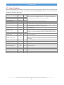
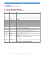
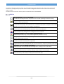
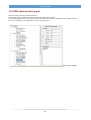
6.7 System Variables
Variables of type System are variables already defined by operative system, therefore we must not to declare them but
they can be used as commen variables. This is the list of the SYSTEM VARIABLES available. There are more system
variables but reserved to the system.
TYPE
R/W
_SYSTEM_PXC
NAME
LONG
R/W
DESCRIPTION
_SYSTEM_PYC
LONG
R/W
_SYSTEM_PZC
LONG
R/W
_SYSTEM_PAC
LONG
R/W
_SYSTEM_ACT_PAGE
INT
R
It contains the page number currently loaded/displayed.
_SYSTEM_OLD_PAGE
INT
R
It contains the page number previously loaded/displayed.
_SYSTEM_STRING(128)
CHAR
R
Array of 128 elements containing the string read by the function Get_TabStr(…..)
_SYSTEM_LINGUA
CHAR
R/W
_SYSTEM_EMCY(8)
CHAR
R
_SYSTEM_SDOAC0
LONG
R
_SYSTEM_SDOAC1
LONG
R
_SYSTEM_TLUCE
LONG
R/W
It contains the response time in milliseconds of the automatic turn off of the background
light in devices with HMI.
They are used in systems with NGM13 and contain . Contengono the double value of
the number of steps generated by the four axis step controller.
It contains the number of LANGUAGE currently used by application. It is a number from
0 to 127 which select the messages from the relative table.
It contains the data frame of Emergency Object of CanOpen. It is updated calling the
function read_emcy().
These variables form the 8 byte of the eventual SDO ABORT CODE sended by a slave
CANOPEN as a result of a call to the functions pxco_sdodl(...) or pxco_sdoul(...). If the
retur value is 2, the variables _SYSTEM_SDOAC0 and _SYSTEM_SDOAC1 represent the
error code.
_SYSTEM_PLC_ACT_TIME
UINT
R
It is the actual elapsed time of TASK PLC in CPU units. DEBUG application displays it in
milliseconds. It useful for test to understand the stress of CPUin TASK PLC. This time
should be less than 30% of the sample time (set in general options) to avoid the other
tasks run slowly.
_SYSTEM_PLC_MAX_TIME
UINT
R
It's similar to the previous but it contains the maximum value latched.
_SYSTEM_CARD_TYPE
INT
R
If there is present an internal SSD this variable contains its dimension in Mbyte (8, 16,
32, 64, 128, etc.).
_SYSTEM_VER
INT
R
It is the firmware version. Ex. 10317 → Vers. 1.03.17
_SYSTEM_CANERR_CNT0
LONG
R/W
Error counter of the Canopen channel 1. It is updated each sample of TASK PLC testing
the hardware interface.
_SYSTEM_CANERR_CNT1
LONG
R/W
It's tha same as the previous one but it refers to channel 2.
_SYSTEM_ECERR_CNT
LONG
R/W
Error counter of the ETHERCAT line.
_SYSTEM_STDINP_DN
INT
R
It contains the code of a key when it is pressed.
_SYSTEM_STDINP_UP
INT
R
It contains the code of a key when it is released.
27
VTB USER GUIDE
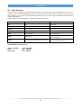
6.8 Static Variables
The variables of type STATIC are declared in NON-VOLATILE RAM: they aren't zeroed at reset and maintain their value
also after turn off. They are very useful to retain data which change frequently (as encoders, counters, etc.), and which
could not be saved in flash memory (IMS). Besides they are common variables.
STATIC variables are always GLOBAL that is visible in all page and in all tasks.
TYPE
DIMENSION
RANGE
BIT
1 bit
From 0 to 1
CHAR
8 bit signed
From –128 to +127
UCHAR
8 bit unsigned
From 0 to 255
INT
16 bit signed
From –32.768 to +32.767
UINT
16 bit unsigned
From 0 to 65.535
LONG
32 bit signed
From –2.147.483.648
to +2.147.483.647
FLOAT
64 bit (standard DOUBLE format IEEE 75)
From -1,79769313486232e308
to +1,79769313486232e308
ARRAY
Single dimension for all variable types
except BIT type
DELEGATE
Pointer to FUNCTIONS
32 bit
ATTENZIONE: Not all systems support the STATIC variables, then refer to hardware manual.
28
VTB USER GUIDE
6.9 Fixed Variables
The variables of type FIXED are allocated at a fixed address in the internal memory of the device which, unlike common
variables, doesn't change modifying the program. This type of variable simplifies the use of systems connected to an
external HOST (ex. PC). In fact using FIXED variables there will be no need to recompile the HOST application at each
change in VTB program.
FIXED variables are always GLOBAL that is visible in all page and in all tasks.
TYPE
DIMENSION
RANGE
BIT
1 bit
From 0 to 1
CHAR
8 bit signed
From –128 to +127
UCHAR
8 bit unsigned
From 0 to 255
INT
16 bit signed
From –32.768 to +32.767
UINT
16 bit unsigned
From 0 to 65.535
LONG
32 bit signed
From –2.147.483.648
to +2.147.483.647
FLOAT
64 bit (standard DOUBLE format IEEE 75)
From -1,79769313486232e308
to +1,79769313486232e308
The START address of FIXED area is:
NGM13 - NGMEVO
NG35
NGQ - NGQx
Addr= 536874496
Addr= 1051648
Addr = 8389632
29
VTB USER GUIDE
6.10 Delegates
This type of variables is used to call a function by a variable. First of all the address of the function to call must be written
in the DELEGATE variable. Then we can use this variable to call the function with the instruction call_delegate. It can
also be created an array of DELEGATE variables and then call a function according to the index of the delegate.
Using of DELEGATES is very powerful because it allows the access to the functions in the fastest way without writing a
long series of conditional cycles.
WARNING: The function called by CALL_DELEGATE must be VOID both for arguments and return parameter.
VTB doesn't make any control to the initialization of the DELEGATE. Calling a delegate not initialized can go the system
in CRASH
Example:
Used variables:
var(2) as delegate
Page Init of Main task (delegates initialization):
Var(0)=fun1
¢ assign to var(0) the address of function fun1
Var(1)=fun2
¢ assign to var(1) the address of function fun2
Page Function of Main task (functions declaration):
Function fun1() as void
.
Endfunction
Function fun2() as void
.
Endfunction
Master Ciclo of Main task (calling of functions by delegates):
Call_delegate var(0)
‘ fun1 will run
Call_delegate var(1)
‘ fun2 will run
30
VTB USER GUIDE
6.11 DEFINE
DEFINES are complex equivalences. They are composed by the NAME and the VALUE. The name identifies the DEFINE,
the VALUE can contain any alfa-numeric expression. The compiler each time a NAME of DEFINE is found, replaces it with
its VALUE. They are very useful to simplify the use of complex expressions or to Parametersze part of code. Also they can
be combined between self.
Declaring of a DEFINE
Using of a DEFINE in the code
To use a DEFINE in text code just we have to write the NAME. DEFINES can be used in a lot of situations making the
program more flexible because it's sufficient to change the VALUE of a DEFINE to obtain an immediate variation on all
the project.
Example:
If Define1>=10000
……………
……………
endif
31
VTB USER GUIDE
6.12 Text Tables
OBSOLETE
6.13 Structures
The STRUCTURES can be declared only as INTERNAL variables. The fields of a structure can be of any type except BIT and
pointer.
To declare a STRUCTURE open the STRUCTURE TABLES and define the NAME of the structure and all single elements we
need.
When a structure is declared, in the list of the variable types the NAME of the STRUCTURE will be showed, allowing to
define a new variable of all types declared as structure.
To use the elements of the structure it's necessary to write the NAME of the STRUCTURE followed by dot character (.)
and by the name of the field at which we want to refer.
It's also possible manage the structures with pointers (see POINTERS chapter).
Example:
Used Variables:
val1 as long
val2 as long
val3 as long
Tool as ToolSTRUCT
’ declaration of a structure variable
Tool.wide=13
val1=Tool.wide
Tool.length=23
Tool.high=54
val2=Tool.length
val3=Tool.high
32
VTB USER GUIDE
7
OPERATORS
The operators of VTB are common to other compilers.
7.1 Logic and Mathematical Operators
These are all the logic and mathematical operators available in VTB:
OPERATOR
DESCRIPTION
EXAMPLE
(
Parenthesis
It identifies the begin of a group of calculation or function a=(c+b)/(x+y)
fun(10,20)
+
Addition
Mathematical addition a=b+c
-
Subtraction
Mathematical subtraction a=b-c
*
Multiplication
Mathematical multiplication a=b*c
/
Division
Mathematical division a=b/c
)
Parenthesis
It identifies the end of a group of calculation or function a=(c+b)/(x+y)
fun(10,20)
>
Greater
Greater than condition if a>b
<
Less
Less than condition if a<b
>=
Greater Equal
Greater or equal than condition if a>=b
<=
Less Equal
Less or equal than condition if a<=b
<>
Not equal
Not equal condition if a<>b
=
Equal
Equal condition if a=b or assignment a=b
||
Logic OR
OR logic condition if (a=b) || (b=c)
condition it's true if at least one expression is true
&&
Logic AND
AND logic condition if (a=b) && (b=c)
condition it's true if both expressions are true
|
OR bit
Execute the OR between two value a=a|3
Bits 1 and 2 of variable a are set leaving unchanged the others
&
AND bit
Execute the AND between two value a=a&3
All bit of variable a are reset except the bits 1 and 2
!
Logic NOT
Negation of an expression if !(a<>b)
The expression is true if a is equal to b
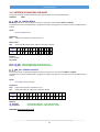
~
NOT bit
Execute a not on all the bits of a value, all bits will change its state
a=85 a=~a
After NOT instruction the variable a will take the value 170
85 → 01010101
170 → 10101010
>>
Shift to right
The bits of the variable are shifted to left n times
a=8 a=a>>3 After shift the variable a will take the value 1
<<
Shift to left
The bits of the variable are shifted to right n times
a=1 a=a<<3 After shift the variable a will take the value 8
33
VTB USER GUIDE
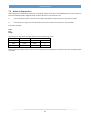
7.2 Notes on Expressions
VTB manages the mathematical expressions completely. Anyway we have to make WARNING when in the expression
there are INTEGER variables together FLOAT variables. We have to remind these rules:
1)
If in the expression there is at least one variable of type FLOAT all the expression is calculated in FLOAT;
2)
If the result of an expression must be FLOAT at least one variable in the expression must be FLOAT;
Look at this example:
A=10
B=4
R=A/B
According to the type of the variables VTB calculates the following results:
A
B
R
LONG
LONG
FLOAT
2
FLOAT
LONG
FLOAT
2,5
FLOAT
FLOAT
LONG
2
Enabling the Warning level of the compiler, some messages will be displayed in coincidence with the possibility of data
truncation.
34
VTB USER GUIDE
8
MATH FUNCTIONS
VTB manages a wide SET of mathematical functions.
8.1 SIN
Return the sinus of an angle in a FLOAT value.
Hardware All
Syntax
Sin (angle) as float
The argument angle can be a FLOAT value or any numeric expression which represents the angle in radians.
Example:
Used variables:
angle float
Cosec float
angle = 1.3
cosec = 1 / Sin (angle)
‘ Define the angle in radians.
‘ Calculate the cosecant.
8.2 COS
Return the cosinus of an angle in a FLOAT value.
Hardware
All
Syntax
Cos (angle) as float
The argument angle can be a FLOAT value or any numeric expression which represents the angle in radians.
Example:
Used variables:
angle float
sec float
angle = 1.3
sec = 1 / Cos (angle)
‘ Define the angle in radians.
‘ Calculate the secant.
8.3 SQR
Return the square root of a number.
Hardware
All
Syntax
Sqr (number) as float
The argument number can be a FLOAT value or any numeric expression greater or equal than zero.
Example
Used variables:
vsqr float
vsqr = sqr (4)
‘ return the value 2
8.4 TAN
Return the tangent of an angle in a FLOAT value.
Hardware
All
Syntax
Tan (angle) as float
The argument angle can be a FLOAT value or any numeric expression which represents the angle in radiant.
35
VTB USER GUIDE
Example:
Used variables:
angle float
ctan float
angle = 1.3
ctan = 1 / Tan (angle)
‘ Define the angle in radians.
‘ Calculate the cotangent.
8.5 ATAN
Return the arctangent of a number in a FLOAT value between -π/2 and +π/2.
Hardware
All
Syntax
Atan (number) as float
The argument number can be a FLOAT value or any numeric expression.
8.6 ASIN
Return the arcsin of a number in a FLOAT value.
Hardware
All
Syntax
Asin (number) as float
The argument number can be a FLOAT value or any numeric expression between 1 and -1.
Example
Used variables:
angle float
var float
angle = 1.3
var = asin (angle)
8.7 ACOS
Return the arccos of a number in a FLOAT value.
Hardware
All
Syntax
Acos (number) as float
The argument number can be a FLOAT value or any numeric expression between 1 and -1.
Example
Used variables:
angle float
var float
angle = 1.3
var = acos (angle)
36
VTB USER GUIDE
8.8 ATAN2
It's similar to atan but it returns a value from -π and +π .
Hardware
All
Syntax
Atan2 (y, x) as float
The arguments y and x are of type FLOAT.
Return Value
The return value coincides with the angle whose tangent is y / x.
Example
Used variables:
x float
y float
angle float
radians float
result float
PI float
PI= 3.141592
x=1.0
y=2.0
angle = 30
radians = angle * (PI/180)
result = Tan(radians)
' Calculate the tangent of 30 degree
radians = Atan(result)
' Calculate the Arctangent of the result
angle = radians * (180/PI)
radians = Atan2(y, x)
' Calculate the Atan2
angle = radians * (180/PI);
8.9 ABS
Return the absolute INTEGER value
Hardware
All
Syntax
Abs (number) as long
The argument number can be a LONG value or any numeric expression.
Example
Used variables:
Num long
Num = -3250
Num = Abs(Num) ‘ return the value 3250
37
VTB USER GUIDE
8.10 FABS
Return the absolute FLOAT value
Hardware
All
Syntax
FAbs (numero) as float
The argument number can be a FLOAT value or any numeric expression.
Example
Used variables:
Num float
Num = -3.250
Num = Abs(Num) ‘ return the value 3.250
38
VTB USER GUIDE
9
INSTRUCTIONS TO CONTROL THE PROGRAM FLOW
In VTB there are a lot of instruction to control the program flow. They are similar to other compiler and THEY ARE
AVAILABLE IN ALL THE HARDWARE TYPES.
9.1 IF-ELSE-ENDIF
Allow the conditional execution of a group of instruction according to the result of an expression.
Syntax
If condition
[instruction]
Else
[instructionelse]
endif
The syntax of instruction if... else is composed by the following elements:
condition
Mandatory. Any expression with the result True (value not zero) or False (value zero).
instruction
List of the instruction to execute if the condition IF is TRUE.
instructionelse Optional. List of the instruction to execute if the condition IF is FALSE.
endif
End of cycle IF ELSE
Notes
The instruction Select Case can be more useful when there are a lot of continuous cycles IF because it creates a source
code more readable.
Example
Used variables:
var1 int
var2 int
if var1*var2 > 120
var1=0
else
var1=120
endif
9.2 LABEL
Identifies a reference point for the GOSUB or GOTO jumps.
Syntax
Label
labelname
labelname
name of the reference of the LABEL.
In each PAGE or MAIN task it can not exist more LABEL with the same name.
WARNING: The LABEL instruction is OBSOLETE. It is preferred to use the FUNCTIONS.
Example
if condiition
goto label1
else
goto label2
endif
.
39
VTB USER GUIDE
Label Label1
.
Label Label2
9.3 GOSUB-RETURN
Allow to pass the control to a SOUBRUTINE and to return at the next program instruction.
Syntax
GoSub labelname
The argument labelname can be any LABEL inside the current PAGE or inside the MAIN task.
Notes
GoSub and Return can be used everywhere in the code, but they must be both included in the same PAGE or in MAIN
task. A subroutine can be composed by more than one Return instructions, but the first Return founded by the
program flow will act the return of the program to the first instruction after the last GoSub..
WARNING: The LABEL instruction is OBSOLETE. It is preferred to use the FUNCTIONS.
Example
if condition
gosub label1
else
gosub label2
endif
Label Label1
Return
Label Label2
Return
9.4 GOTO
Allows to jump to a LABEL.
Syntax
Goto labelname
The argument labelname can be any LABEL inside the current PAGE or inside the MAIN task.
Notes
Goto passes the control to a point of the program referenced by a LABEL. Unlike GOSUB the instruction RETURN isn't
necessary.
WARNING: The LABEL instruction is OBSOLETE. It is preferred to use the FUNCTIONS.
Example
if condition
goto label1
else
goto label2
endif
Label Label1
.
Label Label2
40
VTB USER GUIDE
9.5 INC
Increments a variable of any type.
Syntax
Inc varname
The argument varname can be any variable declared in the program.
Description
Inc is the same as VAR=VAR+1 but it is executed more quickly.
Example
INC var1‘var1 is incremented by 1
9.6 DEC
Decrements a variable of any type.
Syntax
Dec varname
The argument varname può essere una qualsiasi variabile dichiarata nel programma.
Description
Dec is the same as VAR=VAR-1 but it is executed more quickly.
Example
DEC var1
‘ var1 is incremented by 1
9.7 SELECT-CASE-ENDSELECT
Allow to execute blocks of instructions according the result of an expression.
Syntax
Select expression
[Case condition_1
[instruction_1]] ...
[Case condition_2
[instruction_n]] …
…
[Case Else
[instructionelse]]
EndSelect
The syntax of the instruction Select Case is composed by the following elements:
expression
condition_n
Mandatory. Any expression.
Mandatory. It can be in two forms: expression, expression To expression.
The keyword To specifies a range of value.
instruction_n
Optional. Instructions executed if the expression matches the condition_n.
instructionelse Optional. Instructions executed if no condition_n is matched.
Notes
If the result of expression equals a condition_n, the following instructions will be executed until the next instruction
Case or Case Else or EndSelect.
If more than one condition_n is matched, only the first encountered will be execute. Case Else is used to execute a
block of instruction if no condition are verified. Although it isn't mandatory, it is recommended the use of Case Else
statement in each Select to manage also unexpected value of expression.
More instruction Select Case can be nested. At each instruction Select Case there must be an associated EndSelect.
41
VTB USER GUIDE
Example
Used variables:
var1 int
var2 int
var3 int
Select var1
case 10
‘ if var1=10
...
case var2+var3 ‘ if var1=var2+var3
...
case 5 TO 20
‘ if var1 is between 5 and 20
...
case 1,6,8
‘ if var1=1 or var1=6 or var1=8
...
case else
‘ all other value of var1
...
Endselect
9.8 FOR-NEXT-STEP-EXITFOR
Allow the iteration of a block of instructions for a number of times according to a variable. It is a mix between BASIC
and C languages.
Syntax
For counter = init To condition [Step increment]
[intructions]
…
ExitFor
…
Next [counter]
The syntax of the instruction For...Next is composed by the following elements:
counter
init
condition
increment
instructions
ExitFor
Mandatory. Numeric variable used as counter of iteration. It can be a BIT variable.
Mandatory. Initial value of the counter.
Mandatory. Iteration will continue until condition is true.
Optional. Value added to the counter at the end of each iteration. If it isn't specified it will
assume the value 1. It can be any numeric expression and can assume any value positive as
well as negative.
Optional. Block of instructions to execute during the iteration.
It is used to force the stop of the iterations, the program will continue from the line
immediately after the instruction Next.
Notes
It is possible to nest more cycles For...Next Assigning to each cycle a different counter:
Examples
For I = 1 To I<10
For J = 1 To J<10
For K = 1 To K<10
...
Next K
Next J
Next I
42
VTB USER GUIDE
For var1=0 to var1<8
...
Next var1
‘ Repeat 8 times
For var1=1 to var1<var4 step var3
...
Next var1
For var2=1 to var2<=10
...
Next var2
For var1=10 to var1<var3*var4 step –1
...
Next var1
9.9 WHILE-LOOP-EXITWHILE
Allow the execution of a block of instructions until a condition is true.
Syntax
While condition
[instructions]
…
ExitWhile
…
Loop
The syntax of the instruction While...loop is composed by the following elements:
condition
instructions
Mandatory. Any expression with the result True (value not zero) or False (value zero).
Optional. Block of instructions executed until condition is true.
ExitWhile
It is used to force the stop of the cycle, the program will continue from the line immediately
after the instruction Loop.
Notes
If the condition is True, the block of instruction will be executed then yhe cycle will be repeated.
More cycles While...loop can be nested at any level. Each instruction loop will correspond to the more recent
instruction While.
Example
Used variables:
Var1 int
while var1<10
...
loop
43
VTB USER GUIDE
10 FUNZIONI
VTB manages functions with the same syntax as VISUAL BASIC. It exist a limitation in the declaration of internal variables:
they can not be ARRAYS, STRUCTURES or BITS.
10.1 Declaration of a function
Syntax
function function_name(par_1 as int, par_2 as char, ….., par_n as *long) as function_type
dim var as int
‘local variables
....
....
‘body of the function
....
function_name = return_value
endfunction
The syntax of a function is composed by the following elements:
function
function_name
par_1...par_n
function_type
local variables
body of the function
function_name=…
endfunction
Mandatory. Keyword identifying the begin of a function.
Mandatory. Unambiguous name of the function chosen by programmer.
Optional. They are the parameter passed to the function. If no parameter have to be
passed (VOID) there must be nothing inside the parenthesis.
Mandatory. It defines the data type returned from the function. If no data have to be
returned write as void.
Optional. Local variables are allocate at the moment when function is called and
then destroyed when it returns.
They can be of any types except ARRAYS, STRUCTURES or BITS.
Optional. Block of instruction execute by the function.
Optional. It assigns the value returned from the function.
Mandatory. Keyword to identifying the end of the function.
Notes
A function can be called simply writing its name passing to it the eventual parameters declared.
To return from the function in any moment it can be used the instruction return.
The assignment nome_funzione = …. doesn't cause the return from the function but only the assignment of the return
value.
Example:
Used variables:
result as int
number_a as int
number_b as int
Page Function of Main task (functions declaration):
function int_average(number_1 as int, number_2 as int) as int
dim temp as int
temp=(number_1+number_2)/2
int_average=temp
endfunction
Anywhere in the source code (function calling):
number_a=13
number_b=33
result=int_average(number_a, number_b)
44
VTB USER GUIDE
10.2 Declaration of the function internal variables
Syntax
Dim varname as type
The syntax of instruction dim is composed by the following elements:
varname
type
BITS.
Mandatory. Name of the variable.
Mandatory. Type of the variable. It can be of any types except ARRAYS, STRUCTURES or
Example
dim var as long
dim var1 as uint
dim var2 as float
45
VTB USER GUIDE
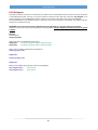
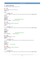
11 SYSTEM FUNCTIONS
VTB provides a wide LIBRERY to a complete management of the hardware devices. Some function can be available only
for some type of hardware
11.1 FUNCTIONS FOR THE SERIAL PORT CONTROL
All Promax hardware devices have 1 or 2 serial channel available to the application.
In VTB there are some object to manage the common serial protocol, for example MODBUS protocol both MASTER and
SLAVE. However it's possible to use one serial channel to customize the protocol.
To do that there are some API function which always refer to the SECOND SERIAL PORT of the hardware.
SER_SETBAUD
Programming the BaudRate of the second SERIALE PORT.
Hardware
All
Syntax
SER_SETBAUD (long Baud)
Parameters
Baud
Value of Baud Rate. The standard value are:
1200-2400-4800-9600-19200-38400-57600-115200
SER_MODE
Programming the mode of the second SERIAL PORT. If this function is never called, by default the port is programmed
with: No parity, 8 bits per character, 1 stop bit.
Hardware
All
Syntax
SER_MODE(char par, char nbit, char nstop)
Parameters
par
nbit
nstop
Example
ser_mode(1,8,2)
Parity (0=no parity, 1=odd parity, 2=even parity)
Number of bits per character (7 or 8)
Number of stop bits (1 or 2)
‘ Program the 2nd serial port with:
‘ ODD-PARITY, 8 BIT/CHAR 2 STOP-BIT
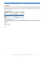
SER_GETCHAR
Reads the receive buffer of the serial port. It doesn't wait for the presence of a character.
Hardware
All
Syntax
SER_GETCHAR () as int
Return value:
-1
>=0
No character is in the buffer
Code of the character read from the buffer
46
VTB USER GUIDE
SER_PUTCHAR
Sends a character to the serial port.
Hardware
All
Syntax
SER_PUTCHAR (int CodeChar)
Parameters
CodeChar
Code of the character to send
SER_PUTS
Sends a string of characters to the serial port. The string must be ended with the character 0 (NULL).
Hardware
All
WARNING: This function can not be used in a BINARY transmision but only with ASCII transmision.
Syntax
SER_PUTS (char *str)
Parameters
*str
Pointer to the string
Example
Ser_puts("TEXT MESSAGE")
Strcpy(Vect(),"MESSAGE1")
Ser_puts(Vect())
‘ Send the string TEXT MESSAGE
‘ Copy the string MESSAGE1 to Vect
‘ Send again the string TEXT MESSAGE
SER_PRINTL
Formatting print of an INTEGER value.
Hardware
All
Syntax
SER_PRINTL (const char *Format, long Val)
Parameters
Format
Val
String corresponding to the format to be printed
Any integer value or expression
Avalaible formats
######
Print a fixed number of characters
###.###
Force the print of decimal point
+####
Force the print of the sign
#0.##
Force the print of a ZERO
X####
Print in HEXADECIMAL format
B####
Print in BINARY format
23456
123.456
+1234
0.12
F1A3
1011
Example
var=12345
ser_printl(“###.##”,var) ‘ It will be printed: “123.45”
var=2
ser_printl(“###.##”,var) ‘ It will be printed: “ . 2”
ser_printl(“###.00”,var) ‘ It will be printed: “ .02”
ser_printl(“##0.00”,var) ‘ It will be printed: “ 0.02”
47
VTB USER GUIDE
SER_PRINTF
Formatting print of a FLOAT value. It is the same as ser_printl but use a float value
Hardware
All
Syntax
SER_PRINTF (const char *Format, float Val)
Parameters
Format
Val
String corresponding to the format to be printed
Any integer value or expression
SER_PUTBLK
Sends a precise number of characters to the serial port. Unlike the function ser_puts it allows to send also the
character with 0 code enabling the managing of binary protocols, furthermore it starts the background transmission
setting in appropriate mode the RTS signal useful to work with RS485 lines.
Hardware
All
WARNING: This function allows to manage BINARY and RS485 protocols.
Syntax
SER_PUTBLK (char *Buffer, int Len)
Parameters
*Buffer
Len
Pointer to the data buffer to send
Number of bytes to send
Example
Ser_putblk(Vect(),11)
‘ Send 11 bytes of array vect
SER_PUTST
Reads the state of background transmission started by ser_putblk.
Hardware
All
Syntax
SER_PUTST () as int
Return value:
-1
>=0
Transmit error
Number of characters to be transmitted
Example
Ser_putblk(Vect(),11)
while Ser_putst()
loop
‘ Send 11 bytes
‘ Wait for the complete transmission
48
VTB USER GUIDE
11.2 MISCELLANEOUS API FUNCTIONS
GET_TIMER
Reads the system timer in units of TASK PLC (scan time).
Hardware
All
Syntax
Long GET_TIMER ()
Return value:
Value of the system timer in sampling units
Some defines are automatically generated by VTB to adapt the application at the scan time:
TAU
Scan time of TASK PLC in milliseconds (INTEGER value)
TAUFLOAT
Scan time of TASK PLC in milliseconds (FLOAT value)
TAUMICRO
Scan time of TASK PLC in 0.1 milliseconds
Example
Used variables:
Tick long
Tick=Get_timer()
while Test_timer(Tick,1000/TAU)
Loop
‘ Get initial value of timer
‘ Waiting for 1 second
PAGINA
Sets the page to be loaded and displayed. Pages are numbered starting from 1. The new page will be loaded not
immediately but at the next cycle of the cooperative task.
Hardware
All
Syntax
PAGINA (int Page)
Parameters
Page
Number of the page to be loaded
TEST_TIMER
Compares the system timer with a value. It is used together the function get_timer to make timing.
Hardware
All
Syntax
char TEST_TIMER (long Timer, long Time)
Parameters
Timer
Time
Initial value of system timer
Time to compare
Return value:
1= time elapsed
0=time not elapsed
Example
Used variables:
Tick long
Tick=Get_timer()
while Test_timer(Tick,1000/TAU)
Loop
‘ Get initial value of timer
‘ Waiting for 1 second
49
VTB USER GUIDE
ALLOC
Dynamic allocating of memory area.
Hardware
NG35
Syntax
ALLOC (Long Mem) as long
Parameters
Mem
Total amount of memory to be allacated
Return value:
<>0
Pointer to the allocated memory
0
Allocation error
Example
Pnt As *Char
N as Long
Pnt=Alloc(3000)
FOR N=0 to N<3000
PUNT[N]=N
NEXT N
‘ Alloc 3000 byte of memory
FREE
Frees the a memory area previously allocated with alloc.
Hardware
NG35
Syntax
Free (Char *Pnt)
Parameters
Pnt
Pointer to the memory to free
Example
Pnt As *Char
Pnt=Alloc(3000)
....
....
Free(pnt)
‘ Alloc 3000 bytes of memory
‘ Free the memory
SYSTEM_RESET
Executes a software RESET on the hardware.
Hardware
All
Syntax
SYSTEM_RESET (Char mode)
Parameters
mode
=0
=1
Executes a normal RESET running the application
Executes a RESET putting device in BOOT state
50
VTB USER GUIDE
11.3 API FUNCTIONS FOR MANAGING OF STRINGS
VTB doesn't use STRING variables, to manage them there are some apposite functions similar to the “C” language.
STRCPY
Copies the string pointed by SOURCE into the array pointed by DEST. The string must terminate with the character 0
(NULL).
Hardware
All
Syntax
STRCPY (Char *Dest, Char *Source)
Parameters
Dest
Source
Pointer to destination
Pointer to source
Example
Used variables:
Dest(10) char
Dest1(10) char
strcpy(Dest(),”My Text”) ‘ copy the string “My Text” in dest
strcpy(Dest1(),Dest())
‘copy the string “My Text” in dest1
STRLEN
Returns the length of a string.
Hardware
All
Syntax
STRLEN(Char *Str) as int
Parameters
Str
Pointer to the string
Return value:
Length of the string.
Example
Used variables:
Len int
Len=StrLen(”My Text”)
‘ return value 7
STRCMP
Comparing of two strings.
Hardware
All
Syntax
STRCMP(Char *Str1, Char *Str2) as char
Parameters
Str1
Str2
Pointer to the first string
Pointer to the second string
Return value:
0
Equal strings
<
String Str1 less than Str2
>0
String Str1 greater than Str2
51
VTB USER GUIDE
STRCAT
Appends a copy of the source string to the destination string.
Hardware
All
Syntax
STRCMP(Char *Dest, Char *Source)
Parameters
Dest
Source
Pointer to destination
Pointer to source
Example
Used variables:
Str(30) Char
Strcpy(Str(),”My “)
StrCat(Str(),”Text”)
‘ str will contain “My Text”
STR_PRINTL
Converts an INTEGER variable to a characters STRING.
Hardware
All
Syntax
STR_PRINTL(Char *Dest, Char *Format, Long Val)
Parameters
Dest
Format
Val
Pointer to the destination string
String corresponding to the format to be printed
Any integer value or expression
Avalaible formats
######
Print a fixed number of characters
###.###
Force the print of decimal point
+####
Force the print of the sign
#0.##
Force the print of a ZERO
X####
Print in HEXADECIMAL format
B####
Print in BINARY format
23456
123.456
+1234
0.12
F1A3
1011
Example
var=12345
STR_Printl(“###.##”,var) ‘ It will be printed: “123.45”
var=2
STR_Printl (“###.##”,var) ‘ It will be printed: “ . 2”
STR_Printl (“###.00”,var) ‘ It will be printed: “ .02”
STR_Printl (“##0.00”,var) ‘ It will be printed: “ 0.02”
STR_PRINTF
Converts a FLOAT variable to a characters STRING.
Hardware
All
Syntax
STR_PRINTF(Char *Dest, Char *Format, Float Val)
Parameters
Dest
Format
Val
Pointer to the destination string
String corresponding to the format to be printed
Any float value or expression
52
VTB USER GUIDE
Avalaible formats
######
###.###
+####
#0.##
X####
B####
Print a fixed number of characters
Force the print of decimal point
Force the print of the sign
Force the print of a ZERO
Print in HEXADECIMAL format
Print in BINARY format
23456
123.456
+1234
0.12
F1A3
1011
11.4 FUNCTIONS FOR AXES INTERPOLATION
The axis interpolation functions are contained in an OBJECT in the CLASS COBJINTERPOLA. In this chapter are descriped
this function with the primitive name. Remember to put the prefix of the OBJECT NAME. If, for example the object is
named obj the function moveto will must be called as obj.moveto.
PROPERTY
This is the list of the common properties of the OBJECT COBJINTERPOLA.
N.assi
N.tratti
.vper
Div.vper
Abilita arcto
.acc
.sglr
.sglp
.sgl3d(NASSI)
.pc(NASSI)
.cmd
Number of axis to be interpolate. It can be changed only at VTB environment.
A DEFINE named Objname.Nassi is automatically generated with this value.
Number of elements in the movement buffer. It can be changed only at VTB environment
and must have a value as power of 2 (4, 8, 16, etc.). A DEFINE named Objname.Ntratti is
automatically generated with this value.
Value for the changing of the speed “on-fly”. Together Div.vper form a ratio: when it is 1 the
speed corresponds to the set one.
Divisor of vper. It can be changed only at VTB environment.
Usually it is set to 1, if 0 the circular interpolation functions will be not avalaible. It is used to
short the code size. It can be changed only at VTB environment.
Acceleration and deceleration. During the execution of ramps, at each sample (TASK PLC) the speed,
as unit/sample is incremented (o decremented) of this value. Default value 10.
Threshold of the radius error. Default value 10.
Threshold edge 2D as tenth of degree. It is used by moveto and lineto to calculate the
presence of an edge on the working plane. Default value 10.(20 degrees).
Threshold edge 3D. Default value 0.2 (for all axis).
Actual calculated value of the axis position.
Output of virtual axis managed by setcmd.
MOVETO
Movement with linear interpolation. The interpolation is executed at speed vel. The parameter mode defines if the
axis have to stop in the position or continue with the next movement. To do that there is a apposite BUFFER where
movement are latched.
Hardware
All
Syntax
.MOVETO(Long Vel, Char mode, Long *PntAx) as char
Parameters
Vel
Velocity of interpolation as unit/sample
mode
Flag to control the stop before the next movement
mode=0 never stop
mode=1 always stop at the end of movement
mode=2 stop only on edge 3D (sgl3d)
mode=3 stop only on edge 3D (sglp)
PntAx
Pointer to the array of the axis position as unit
Return value
53
VTB USER GUIDE
Char
0
1
Command not written in the buffer (buffer full)
Command written in the buffer
Notes
Moveto is usually used to interpolate more than 2 axes. The speed vector is distributed on all axes to be interpolated.
When mode=2 it is calculated the presence of a multidimensional edge according to the values in sgl3d. When mode=2
the test of edge is made only on the axis of the working plane and according to the value in sglp. If the comand isn't
written in the BUFFER, we have to wait and repeat otherwise it will be lost.
Approximative reference values of parameter SGL3D
THRESHOLD in DEGREE
VALUE OF SGL3D (min-max)
5
60-90
10
125-175
20
250-350
30
300-500
45
400-700
Example (object name = OBJ)
Used variables:
VectAssi(4) long
Vel long
Test char
'*******************************************************************************
'Fast interpolation of several segments on axis X,Y holding Z and A stopped
'*******************************************************************************
vel=1000
VectAssi(0)=1000 'X
VectAssi(1)=2000 'Y
VectAssi(2)=OBJ.pc(2) 'Z remain stopped
VectAssi(3)=OBJ.pc(3) 'A remain stopped
muovi()
VectAssi(0)=4000 'X
VectAssi(1)=6000 'Y
VectAssi(2)=OBJ.pc(2) 'Z remain stopped
VectAssi(3)=OBJ.pc(3) 'A remain stopped
muovi()
VectAssi(0)=5000 'X
VectAssi(1)=2000 'Y
VectAssi(2)=OBJ.pc(2) 'Z remain stopped
VectAssi(3)=OBJ.pc(3) 'A remain stopped
muovi()
‘ *********************************************************
‘ Movement function waiting if the buffer is full
‘ *********************************************************
Function muovi() as Void
Dim test as Char
Label Move
test=Obj.moveto(vel,3,VectAssi())
if test=0
goto Move
endif
EndFunction
54
VTB USER GUIDE
LINETO
Lineto interpolates the axis distributing the vector speed ONLY ON THE AXES OF THE CURRENT WORKING PLANE. The
other axis will be TRANSPORTED.
The function is useful to manage TANGENTIAL AXIS such as cutting machine, where the blade have to be transported to
increasing the fluidity of the movement. The eventual stop of axis is calculated according to the threshold value in sglp.
If the resultant edge is less or equal than this threshold axis don't stop in the position but continue filleting the two
segments.
Hardware
All
Syntax
.LINETO(Long Vel, Long *PntAx) as char
Parameters
Vel
PntAx
Velocity of interpolation as unit/sample
Pointer to the array of the axis position as unit
Return value
Char
0
1
Command not written in the buffer (buffer full)
Command written in the buffer
Notes
Lineto, unlike Moveto, doesn't distribute the velocity on all enables axis, but only on the working plane making this
function not able to tridimensional interpolation.
If the edge is less or equal than SGLP axis don't stop
Example (object name = OBJ)
Used variables:
VectAssi(4) long
Vel long
Test char
‘ Fast interpolation with tansported third axis
vel=1000
VectAssi(0)=1000 'X
VectAssi(1)=2000 'Y
VectAssi(2)=100 'Z transported
VectAssi(3)=OBJ.pc(3) 'A remain stopped
muovi()
VectAssi(0)=4000 'X
VectAssi(1)=6000 'Y
VectAssi(2)=200 'Z transported
VectAssi(3)=OBJ.pc(3) 'A remain stopped
muovi()
VectAssi(0)=5000 'X
VectAssi(1)=2000 'Y
VectAssi(2)=300 'Z transported
VectAssi(3)=OBJ.pc(3) 'A remain stopped
muovi()
55
VTB USER GUIDE
‘ *********************************************************
‘ Movement function waiting if the buffer is full
‘ *********************************************************
Function muovi() as Void
Dim test as Char
Label Move
test=Obj.lineto(vel,VectAssi())
if test=0
goto Move
endif
EndFunction
ARCTO
Movement with CIRCULAR interpolation on the axes of the current WORKING PLANE. Two axes execute a CIRCULAR
interpolation while the others are interpolated in LINEAR mode. As function LINETO, the property sglp defines the edge
threshold for axis stopping. The direction of rotation is determined by the parameter mode.
Hardware
All
Syntax
.ARCTO(Long Vel, Char mode, Long *PntAx, Long CX, Long CY) as char
Parameters
Vel
mode
PntAx
Cx,CY
Velocity of interpolation as unit/sample
Direction of rotation
mode=2 CW interpolation
mode=3 CCW interpolation
Pointer to the array of the axis position as unit
Coordinate X,Y (axis of the working plane) of the CENTER
Return value
Char
0
Command not written in the buffer (buffer full)
1
Command written in the buffer
-1
Radius error (dipends by sglr)
Note
Arcto executes a CIRCULAR interpolation ON WORKING PLANE while the other axis are interpolated in LINEAR MODE.
Example (object name = OBJ)
Used variables:
VectAssi(4) long
Cx long
Cy long
Vel long
'**********************************************************
'Circular interpolation CW on X,Y Z and A
'to realize the programmed arc the axis X and Y must be in precise positions, for Example at 0,2000
‘**********************************************************
vel=1000
VectAssi(4) long
VectAssi(0)=1000‘ final position X
VectAssi(1)=2000‘ final position Y
VectAssi(2)=5000‘ final position Z
VectAssi(3)=1000‘ final position A
Cx=500 ‘center X
Cy=500 ‘center Y
muovi()
56
VTB USER GUIDE
Function muovi() as Void
Dim test as Char
Label Move
test=px_arcto(vel,2,VectAssi(), Cx, Cy)
if test = 0
goto Move
endif
EndFunction
SETCMD
This function allows the synchronization of commands with the axis movement. In fact because of BUFFER OF AXIS
MOVEMENT the interpolation functions don't wait the execution of the command but write it in the buffer. This implies
the impossibility to command, for example, the digital output in a precise point of the path if axis don't stop in each
position. This function enables the writing of a command value in the buffer when a interpolation function is called
(moveto, lineto, arcto), it will be written in cmd at the instant the movement starts.
Hardware
All
Syntax
.SETCMD(Long CMD)
Parameters
CMD
Value of the command
Example
muovi()
OBJ.setcmd(10)
muovi()
OBJ.setcmd (20)
‘Insert the following code in the TASK PLC
if OBJ.CMD=10
…
endif
if OBJ.CMD=20
…
endif
SETPIANO
Selects the current working plane on desired axis. By default the plane is set on the first two axis X, Y (ax1=0, ax2=1).
Ax1 can not be equal to ax2.
Hardware
All
Syntax
.SETPIANO(Char Ax1, Char Ax2)
Parameters
Ax1
Index of the first axis of the plane
Ax2
Index of the second axis of the plane
Note
The WORKING PLANE selects the axis for the CIRCULAR interpolation, for calculation of the edge 2D (sglp) and for
calculation of the SPEED VECTOR in the function LINETO.
Example
Obj.setpiano(0,1)
Obj.setpiano(1,2)
'select the plane on axis X and Y
'select the plane on axis Y and Z
57
VTB USER GUIDE
STOP
Stops axis with the programmed deceleration (acc) waiting for the complete execution (axis stopped).
STOP is used to stop the axis before the TARGET point, programmed with MOVETO, LINETO or ARCTO, is reached. The
movement buffer will be emptied.
Hardware
All
Syntax
.STOP()
Notes
STOP, unlike FSTOP, waits the axis are stopped, for this IT MUST NOT BE CALLED IN TASK PLC.
FSTOP
Stops axis with the programmed deceleration (acc) without waiting for the complete execution (axis stopped).
FSTOP is used to stop the axis before the TARGET point, programmed with MOVETO, LINETO or ARCTO, is reached. The
movement buffer will be emptied.
Hardware
All
Syntax
FSTOP()
Note
FSTOP, unlike STOP, doesn't wait the axis are stopped, for this IT CAN BE CALLED IN TASK PLC.
MOVE
Returns the state of the interpolation.
Hardware
All
Syntax
.MOVE() as char
Return value
char
0
1
No interpolation is running
Interpolation is running
Note
MOVE retunrs 0 only the axis are stopped and the movement buffer is empty.
ATTENZIONE: MOVE tests only the DEMAND POSITION of AXIS.
Example
Muovi()
‘start interpolation
while Obj.move()
‘wait for complete execution
endif
PRESET
Preset the AXIS position without move them. Axis will assume the position as passed by parameters.
Hardware
All
Syntax
.PRESET(long *Pos)
Parameters
Pos
Pointer to the array of the position value to preset
58
VTB USER GUIDE
Note
Keep in mind these rules:
–
–
AXIS MUST BE STOPPED
CHANGING INSTANTLY THE POSITION IT OCCURS A PARTICULAR SEQUENCE TO AVOID THE PHISICAL AXIS
MOVES ROUGHLY
For example WHEN USING THE CANOPEN AXIS IT NEEDS:
–
REMOVING THE CANOPEN FROM THE INTERPOLATION MODE
–
PRESETTING THE CANOPEN AXIS BY METHOD .HOME
–
PRESETTIN THE INTERPOLATOR WITH FUNCTION PRESET(pos())
–
SETTING AGAIN THE CANOPEN AXIS IN INTERPOLATION MODE
Example with the axis X as CanOpen (object name AxisCan)
Used variables:
PresetValue(3) as long
AxisCan.start=0
AxisCan.modo=0
AxisCan.home=1000
PresetValue (0)=1000
PresetValue (1)=OBJ.pc(1)
PresetValue (2)=OBJ.pc(2)
OBJ.PRESET(PresetValue ())
AxisCan.modo=2
AxisCan.start=1
' remove the start condition
' set the position mode (remove from interpolation mode)
' preset of axis at 1000
' set the preset value in the position array for X
' value to not modify the Y position
' value to not modify the Z position
' preset of the interpolator
' set the Interpolation Mode
' start
In similar way the same problem can occur using the STEP/DIR axis. Refer to the chapter of STEP/DIR channels for a
correct preset of them.
11.5 CANOPEN FUNCTIONS
This group of functions allow the management of CANOPEN line at application level. A lot of library OBJECTS use these
functions to make it more simple but in some cases it is necessary using the primitive functions directly.
PXCO_SDODL
This function allows to send data to a node of the canopen net using the protocol SDO. It is supported only the SDO
EXPEDITED mode allowing to send up to 4byte of data length.
Hardware
All
Syntax
PXCO_SDODL(char node, unsigned index,unsigned char subidx,long len,char *data) as char
Parameters
Node
Index, subindex
Len
*data
Node ID of the SLAVE to whch send data
Address in the Object-Dictionary of the data to be written
Number of bytes to send
Pointer to the data to send
Return value
char
0
No error
<>0
Communication error
=2
The node responded with a SDO ABORT CODE, calling the function read_sdoac in the
system variables _SYSTEM_SDOAC0 e _SYSTEM_SDOAC0 will be available the relative
error code.
WARNING: Cause the different allocation of bytes inside variables be careful to set the length corresponding to the
59
VTB USER GUIDE
variable type passed by pointer.
Example
Used variables:
value int
Ret char
value=100
Ret=pxco_sdodl(1,2000,0,2,value())
'node=1, index=2000, subidx=0,
'len=2 byte, value=100
‘test if error occurs
if Ret<>0
if Ret=2
read_sdoac()‘read eventual SDO ABORT CODE
...
endif
...
endif
PXCO_SDOUL
This function allows to read data from a node of the canopen net using the protocol SDO. It is supported only the SDO
EXPEDITED mode allowing to read up to 4byte of data length.
Hardware
All
Syntax
PXCO_SDOUL(char node, unsigned index,unsigned char subidx,char *dati) as char
Parameters
Node
Node ID of the SLAVE to whch send data
Index, subindex Address in the Object-Dictionary of the data to be written
*data
Pointer to the data to send
Return value
char
0
No error
<>0
Communication error
=2
The node responded with a SDO ABORT CODE, calling the function read_sdoac int the
system variables _SYSTEM_SDOAC0 e _SYSTEM_SDOAC0 will be available the relative
error code.
WARNING: Cause the different allocation of bytes inside variables be careful to use the variable passed by pointer of
the type corresponding to the length of the data to be read.
Example
Used variables:
value int
Ret char
Ret=pxco_sdoul(1,2000,0,value()) 'node=1, index=2000, subidx=0,
'value=data read
if Ret<>0
‘test if error occurs
if Ret=2
read_sdoac()‘read eventual SDO ABORT CODE
...
endif
...
endif
READ_SDOAC
Reading of the SDO ABORT CODE sent by a node in the canopen net as answer to a request done with the function
60
VTB USER GUIDE
PXCO_SDODL or PXCO_SDOUL. The read code will be written in the system variables _SYSTEM_SDOAC0 e
_SYSTEM_SDOAC1.
Refer to the DS301 specific of the CAN OPEN for the code error values.
Hardware
All
Syntax
READ_SDOAC()
PXCO_SEND
Sending of a CAN frame at low level. This function allows to send in the net a CAN frame with a desired COB-ID and
DATS. For example it's possible to send manually PDO frames, HEART-BEAT frames, etc.
Should be specified the manage of PDO is managed AUTOMATICALLY by the CANOPEN CONFIGURATOR.
Hardware
All
Syntax
PXCO_SEND(int id, char Len,char *Data) as char
Parameters
Id
Len
*Data
COB-ID value
Number of data to send
Pointer to the data buffer
Return value
char
0
<>0
No error
Communication error
Example
Used variables:
value int
Ret char
value=100
Ret=pxco_send(0x201,2,value()) ‘Send a PDO (cob-id=0x201) with 2 byte
if Ret<>0
‘test if error occurs
...
endif
PXCO_NMT
Sending of a NMT frame of the CAN OPEN. NMT protocol allows to set the state of the nodes in the net. Remind that all
the nodes correctly configured (canopen configurator) are automatically set in START state.
Hardware
All
Syntax
PXCO_NMT(char state, char node) as char
Parameters
state
node
State to set:
1 = START NODE
2 = STOP NODE
128 = PRE-OPERATIONAL
129 = RESET NODE
130 = RESET COMUNICATION
Number of the node
Return value
char
0
<>0
No error
Communication error
61
VTB USER GUIDE
Example
Used variables:
pxco_nmt(2,1) ‘Set in STOP the node 1
READ_EMCY
Reads the last EMERGENCY OBJECT frame sent by a CAN OPEN node.
The emergency code is written in the system array _SYSTEM_EMCY(8) and it will contain all the 8 bytes of the
EMERGENCY OBJECT frame as from the DS301 specific of the CAN OPEN. Usually it is called cyclically. The emergency
code depends by type of connected device, therefore refer to its manual.
Hardware
All
Syntax
READ_EMCY() as char
Return value
char
0
<>0
No error
Node that generated the emergency object.
_SYSTEM_EMCY
0
1
Emergency Error Code
2
3
4
5
Error
Register
Manufacturer specific Error Code
6
7
WARNING
The system doesn't buffer more than one message, then if more EMERGENCY OBJECT are sended along a single
task plc, only the last will be read.
An EMERGENCY OBJECT non significa che effettivamente ci sia un nodo in emergenza. The DS301 specific provide
that an EMERGENCY OBJECT are send also on alarm reset. Furthermore some devices can be send this frame at
start up.
Example
Used variables:
Err Long
NodeErr Char
function Alarm() as void
NodeErr=read_emcy()
if NodeErr=0
return
endif
err=(_SYSTEM_EMCY(7)&0xff)
err=err<<8
err=err|(_SYSTEM_EMCY(6)&0xff)
err=err<<8
err=err|(_SYSTEM_EMCY(5)&0xff)
err=err<<8
err=err|(_SYSTEM_EMCY(4)&0xff)
endfunction
' no error
' Read 4 byte of Manufactured specific
' field masking eventual bit not
' interested
11.6 DATA SAVING FUNCTIONS
All hardware are equipped with several type of memory usable for DATA SAVING. According to the type of memory (Fash,
Fram, etc.) some rules are to be implemented.
62
VTB USER GUIDE
For example a FLASH memory has a maximum number of writing, block erase, etc.
IMS_WRITE
Writes in the internal FLASH at the address contained in ADDR, the data pointed by Punt for a total of NBYTE of data.
The FLASH memory is managed in BLOCKS of 256 bytes, for this it's recommended to write multiple of 256 bytes. That
because also writing less than 256 bytes the entire BLOCK is erased, therefore to avoid the loss of data it needs at
beginning to read all the block, save the interested data and overwrite again all the block. The systems NG35 or PEC70
have enough FLASH memory to be used without problems in blocks of 256 bytes also there is the need of less data.
Using the NGM13,NGMEVO,NGQ,NGQx, this function works on a FRAM memory which can be managed at single BYTE.
Hardware
All
Syntax
IMS_WRITE(char *Punt, long Addr, long Nbyte) as char
Parameters
Punt
Addr
Nbyte
Pointer to data buffer to be written
Start address in the reserved area of the device
Number of bytes to be written
Return value:
Char
0
<>0
No error
Writing error
Example
Used variables:
Vett(10) long
Ims_Write(Vett(),0,40) ‘ write 40 bytes (10 long * 4) to ADDR 0
WARNING: In this case the entire block of 256 byte is written if we are working with FLASH (NG35).
IMS_READ
Reads from the internal memory at address ADDR a number of byte as in NBYTE and writes them in the array pointed
by Punt.
Hardware
All
Syntax
IMS_READ(char *Punt, long Addr, long Nbyte) as char
Parameters
Punt
Addr
Nbyte
Pointer to data buffer where read data will be saved
Start address in the reserved area of the device
Number of bytes to be read
Return value:
Char
0
<>0
No error
Writing error
Example
Used variables:
Vett(10) long
Ims_Read(Vett(),0,40) ‘ read 40 bytes (10 Long) from Addr 0
11.7 ETHERNET FUNCTIONS
Systems equipped with ETHERNET manage AUTOMATICALLY the STACK TCP/IP. To work with protocols at upper level
than TCP/IP it must be written some source code in the application. For example to process the MODBUS-TCP protocol
there is a specific object in library which uses the functions of this group. In the same way it's possible to create
63
VTB USER GUIDE
customized protocols.
SET_IP
Sets the parameters of TCP/IP protocol.
Hardware
NG35,NGMEVO
Syntax
SET_IP(ip as *char, sm as *char, gw as *char)
Parameters
ip
IP address of the device
sm
subnet mask
gw
gateway
Example
Set_ip(“10,0,0,15”,”255,255,255,0”,0)
'IP = 10,0,0,15
'SUBNET = 255,255,255,0
'GATEWAY = nothing
WARNING: This function must be called in the INIT section of the MAIN or PLC TASK.
PXETH_ADD_PROT
Adds a custom protocol to a specific port of TCP/IP. A custom function to process the new protocol must be written
and its pointer must be pass to this function.
Hardware
NG35,NGMEVO
Syntax
PXETH_ADD_PROT(port as long, fun as delegate)
Parameters
port
TCP port on which the new protocol is added
fun
Pointer to the custom process function
Example
Used variables:
fun delegate
Init section of main:
Set_ip(“10,0,0,15”,0,0) 'set IP = 10,0,0,15
fun=my_protocol
pxeth_add_prot(502,fun) 'Add the protocol my_protocol on port 502
'protocol process function
function my_protocol(len as long, buftx as *char) as long
...
endfunction
64
VTB USER GUIDE
PROTOCOL PROCESS FUNCTION
This function isn't defined by system but it must be written in the application. The system will call this function, by the
pointer passed with pxeth_add_prot, each time a data packet is received from the port associated to this protocol. To
read the received data the function pxeth_rx have to be call while to send the response data they must be written in
the transmit buffer (buftx) and return from the function the number of bytes we want to send.
Hardware
NG35,NGMEVO
Syntax
PROCESS_MY_PROTOCOL(len as long, buftx as *char) as long
Parameters
len
Length of data packet received
buftx Pointer to the transmit buffer
Return value
long
Number of bytes to be send
Example
Used variables:
bufrx(100) char
'protocol process function
function my_protocol(len as long, buftx as *char) as long
dim i as int
for i=0 to i<len
'Read all received data
bufrx(i)=pxeth_rx()
next i
...
'Process the data
buftx(0)=12
buftx(1)=34
my_protocol=2
'2 will be sent as response
endfunction
PXETH_RX
Read a single byte from the TCP/IP receive buffer. It is called by the protocol process function to read the received
data.
Hardware
NG35,NGMEVO
Syntax
PXETH_RX() as char
Return value
Char
Data read from the receive buffer
65
VTB USER GUIDE
11.8 DISK DRIVER FUNCTIONS
Some devices, such as NG35, can manage files by the standard fyle system FAT16 (or FAT32) on optional memory as
FLASH DISK or USB KEY. The library functions are contained in the object FATLIB which will be loaded before using. In this
chapter are described all the GENERIC function of the object. Remember to put the prefix of the OBJECT NAME. If, for
example the object is named disk the function OpenRead will must be called as disk.OpenRead.
Hardware
NG35 with DISK FLASH EXPANSION
PROPERTY
Numero files
FAT Monitor
Maximum number of opened files. The HANDLE of the files will must be a number from 0 to
this value minus one. It can be changed only at VTB environment.
Enables the command monitor on the second serial port. It can be changed only at VTB
environment.
DRIVER
The system can manage mor drivers if they are equipped on hardware. The reference in the path is in the standard
mode (A:, B:, etc.) but for some functions it needs to pass the index of the driver. According to used hardware these
are the reference of the driver:
NG35
A:
B:
Optional internal disk
Not present
ERROR CODE
All function of this object, except TestDrv, RTC.Read and RTC.Write, return a value representing the error code.
Return value
Char
0
1
2
3
4
5
6
7
8
9
10
11
12
13
14
15
100
OK No error
DISK ERROR
INTERNAL ERROR
NOT READY
NO FILE
NO PATH
INVALID NAME
ACCESS DENIED
FILE/DIR EXIST
INVALID OBJECT
WRITE PROTECTED
INVALID DRIVE
NOT ENABLED
NO FILESYSTEM
FORMAT ERROR
TIMEOUT
HANDLE OVERFLOW
OPENREAD, OPENWRITE, OPENCREATE
These function open a file assigning an HANDLE to use as reference for the next functions.
Syntax
.OpenRead(handle as int, path as *char) as char
Opens a file in read mode and return error if it doesn't exist.
.OpenWrite(handle as int, path as *char) as char
Opens a file in write mode and return error if it doesn't exist.
66
VTB USER GUIDE
.OpenCreate(handle as int, path as *char) as char
Creates a new file opening it in write mode, if it already exists it is overwritten.
Parameters
handle
path
Number to assign to file for any reference
Name of the file, it can contain also the complete path
Example
Used variables:
err char
err=disk.OpenRead(1,”\data\table.dat”) ‘ open table.dat in the directory data
if err
...
endif
CLOSE
Closes the file with the selected HANDLE freeing it to successive use.
Syntax
.Close(handle as int) as char
Parameters
handle
Reference number of the file
Example
Used variables:
err char
err=disk.OpenRead(1,”\data\table.dat”) ‘ open table.dat in the directory data
if err
...
endif
...
disk.Close(1) ‘ close the file
READ
Reads data from the file with the selected HANDLE. LEN bytes will be read but if the end of file will be found before
reading will be stopped. In NB will be written the effective number of bytes read.
Syntax
.Read(handle as int, dati as *char, len as long, nb as *long ) as char
Parameters
handle
dati
len
nb
Reference number of the file
Pointer to buffer in which data will be written
Number of bytes to read
Pointer to the variable in which the effective number of bytes read will be written
Example
Used variables:
err char
dati(100) char
nbyte long
67
VTB USER GUIDE
err=disk.OpenRead(1,”\data\table.dat”) ‘ open table.dat in the directory data
if err
...
endif
while 1
err=disk.Read(1,dati(),10,nbyte()) ‘read blocks of 10 bytes ...
if err
...
endif
if nbyte<10
‘ .. to the end of file
exitwhile
endif
loop
disk.Close(1) ‘ close the file
WRITE
Writes LEN bytes in the file with the HANDLE reference.
Syntax
.Write(handle as int, dati as *char, len as long, nb as *long) as char
Parameters
handle
dati
len
nb
Reference number of the file
Pointer to data buffer to be written in the file
Number of bytes to be written
Pointer to the variable in which the effective number of bytes written will be saved
Example
Used variables:
err char
dati(100) char
nbyte long
err=disk.OpenCreate(1,”\data\table.dat”) ‘create table.dat in the directory data
if err
...
endif
...
‘prepare data to be written
err=disk.Write(1,dati(),50,nbyte())‘write 50 bytes
if err
...
endif
disk.Close(1) ‘ close the file
SEEK, SEEKEOF, SEEKREL
Sets the current pointer in the file.
Syntax
.Seek(handle as int, offset as long) as char
Sets the offset from the beginning of the file.
.SeekEof(handle as int, offset as long) as char
Sets the offset from the end of the file.
68
VTB USER GUIDE
.SeekRel(handle as int, offs as long) as char
Sets the offset from the current position of the file.
Parameters
handle
offset
Reference number of the file
Value of the offset in number of bytes
Example
err=disk.OpenRead(1,”\data\table.dat”) ‘ open the file
...
err=disk.Seek(1,200)
‘ set current position at 200 bytes
CHDIR
Changing of current directory. All successive functions without a complete path will refer to the current one.
Syntax
.Chdir(path as *char) as char
Parameters
path
Name of the directory, it can contain also the complete path
Example
err=disk.Chdir(”programs”)
err=disk.OpenCreate(1,”file.txt”) ' create the file file.txt in the directory
' programs
MKDIR
Creates a new directory and returns error if it already exists.
Syntax
.Mkdir(path as *char) as char
Parameters
path
Name of the directory, it can contain also the complete path
Example
err=disk.Mkdir(”\test\text”)
' create the directory text in \test
DELETE, ERASE, KILL
Delete a file or a directory. The same function can be called with three different names.
Syntax
.Delete(path as *char) as char
.Erase(path as *char) as char
.Kill(path as *char) as char
Parameters
path
Name of the directory, it can contain also the complete path
Example
err=disk.kill(”\test\text”) ' delete the directory/file text in \test
RENAME
Renames a file or a directory. It returns error if the new name already exists.
69
VTB USER GUIDE
Syntax
.Rename(oldpath as *char, newpath as *char) as char
Parameters
oldpath Name of file/directory to be renamed
newpath
Name of the new file/directory to be renamed
Example
err=disk.Rename(”text.txt”,”data.dat”)
' rename the file text.txt with
' data.dat in the current directory
COPY
Duplicates a file. If a file with the destination name exists this is overwritten.
Syntax
.Copy(srcpath as *char, dstpath as *char) as char
Parameters
srcpath Name of the file to be duplicated, it can contain also the complete path
dstpath Name of the duplicated file, it can contain also the complete path
WARNING: The destination path must contain the name of the file. It can not refer only to the directory.
Example
err=disk.Copy(”text.txt”,”B:data.dat”)
' copy the file text.txt in driver B:
...
err=disk.Copy(”text.txt”,”\test\data.dat”) ' copy the file text.txt in the
...
' directory test
OPENDIR
Apre una cartella. E' il punto di partenza per una ricerca dei file presenti nel disco. Usata insieme a ReadDir.
Syntax
.OpenDir(path as *char) as char
Parameters
path
Nome della cartella. Se la stringa è vuota viene presa la cartella corrente.
READDIR
Reads the informations of the first file/directory found in the FAT. The informations are saved in the structure
ObjectName_finfo.
Syntax
.ReadDir() as char
Structure ObjectName_finfo
.size
File dimension
.date
File date bit 0-4 day (1-31)
bit 5-8 month (1-12)
bit 9-15 year (0-99)
.time
File time bit 5-10 minutes (0-59)
bit 11-15 hour (0-23)
.attrib
Attribute
bit 0 read-only
70
VTB USER GUIDE
.name(13)
.lname
bit 1 hidden
bit 2 system
bit 3 volume
bit 4 directory
bit 5 arch.
Short name ex. “nomefile.ext”
Pointer to long name (max 255 characters)
Example
' Function to print on the serial port of the file list in the current
' directory
function list_dir() as void
dim res as char
dim pname as *char
dim flbyte as long
res=disk.OpenDir(“”)
if res
ser_puts("No file")
ser_putchar(10)
ser_putchar(13)
return
endif
while 1
res = disk.ReadDir()
if res || disk_finfo.name(0)=0
return
endif
ser_printl("00",disk_finfo.date & 31)
ser_printl("/00",(disk_finfo.date >> 5) & 15)
ser_printl("/####",(disk_finfo.date >> 9) + 1980)
ser_printl(" 00",disk_finfo.time >> 11)
ser_printl(":00",(disk_finfo.time >> 5) & 63)
if disk_finfo.attrib & ?p1?.ATTR_DIR
ser_puts(" <DIR> ")
else
ser_printl(" ######### bytes ",disk_finfo.size)
endif
ser_puts(" - ")
ser_puts(disk_finfo.name())
ser_puts(" - ")
ser_puts(disk_finfo.lname)
ser_putchar(10)
ser_putchar(13)
loop
endfunction
71
VTB USER GUIDE
GETFREE
Reads the property of a driver: total dimension and number of free bytes. The informations are written in the structure
ObjectName_dinfo
Syntax
.GetFree(drv as char) as char
Parameters
drv
Index of the driver:
0 = A:
1 = B:
Structure ObjectName_dinfo
.btot
Disk dimension in bytes
.bfree
Number of available bytes
Example
err=disk.GetFree(0)
ser_puts("bytes free: ")
ser_printl("#.###.###.### ",disk_dinfo.bfree)
ser_puts("su ")
ser_printl("#.###.###.### ",disk_dinfo.btot)
CHDRV
Sets the current driver. All successive functions without the name of driver in the path will refer to the current one.
Syntax
.ChDrv(drv as char) as char
Parameters
drv
Index of the driver:
0 = A:
1 = B:
Example
err=disk.ChDrv(”B:”)
err=disk.OpenCreate(1,”file.txt”) ' create file.txt in driver B:
TESTDRV
Tests the presence of a driver. This is the only function wich doesn't return the code error as the others.
Syntax
.TestDrv(drv as char) as char
Parameters
drv
Return value
Char
0
1
Index of the driver:
0 = A:
1 = B:
No driver found
Driver found
WARNING: This function tests only the presence of the disk but not the presence of a FAT.
72
VTB USER GUIDE
REAL TIME CLOCK (RTC)
When files are created in the relative fields of the FAT the actual date and time are written. For this in the same object
there are the reading and writing functions of the real time clock. All the information pass in a defined structure
names RTC.
Syntax
RTC.Read() as void
Read the Real Time Clock
RTC.Write() as void
Write in the Real Time Clock
Structure RTC
RTC.year
Year (0-99)
RTC.month
Month (1-12)
RTC.day Day (1-31)
RTC.dweek
Day of week (0-6)
RTC.hour
Hour (0-23)
RTC.min Minute (0-59)
RTC.sec Second (0-59)
73
VTB USER GUIDE
11.9 INTERFACE FUNCTIONS FOR NG35
This group of functions allows the interfacing to the hardware resource of NG35 systems.
Hardware
NG35
NG_DI - DIGITAL INPUTS
This function allows to read the digital input of the expansion cards of NG35: NG-IO and NG-PP.
The expansion cards are identified with a progressive number starting from 0. The first card near the NG35 has the
index 0.
Syntax
Uint NG_DI(Char Card)
Parameters
Card
Index of the expansion card (from 0 to 7)
Return value:
Uint
Value of 16 BITS of the input, if Bit is 1 the input is ACTIVE
Input
16 15 14 13 12 11 10 9 8 7 6 5 4 3 2 1
Bit
15 14 13 12 11 10 9 8 7 6 5 4 3 2 1 0
Example
Used variables:
input UINT
input = ng_di(0) ‘ read the digital inputs from the first card
input = ng_di(2) ‘ read the digital inputs from the second card
NG_DO – DIGITAL OUTPUTS
This function allows to updates the digital output of the expansion cards of NG35: NGIO and NGPP.
The expansion cards are identified with a progressive number starting from 0. The first card near the NG35 has the
index 0.
Syntax
NG_DO(Char Card, Uint Out)
Parameters
Card
Index of the expansion card (from 0 to 7)
Out
State of the outputs, if Bit is 1 the output is ACTIVE
Output
Bit
14 13 12 11 10
9
15 14 13 12 11 10
9
Example
ng_Do(0,0x7)
ng_Do(1,0x31)
8
8
7
6
5
4
3
2
1
7
6
5
4
3
2
1
0
‘ Activate the outputs 1, 2 and 3 of the Card 0
‘ Activate the outputs 1, 9 and 10 of the Card 1
WARNING: Bits 8 and 15 aren't used.
74
VTB USER GUIDE
NOTES FOR PROGRAMMING WITH DIGITAL I/O
To obtain an application program more clear and stable we suggest to call the I/O function only from TASK PLC. Therefore,
in this task, read the inputs writing them in a GLOBAL variable (ex. Input) and write the outputs reading them from
another GLOBAL variable (ex. Output). On these variables can be defined the single bits associated to the digital channels
and then using them at occurrence.
Example
Used variables:
Input1 UINT
Input2 UINT
Output1 UINT
Output2 UINT
StartButton BIT Input1.3
StopButton BIT Input1.6
WaterPump BIT Output2.12
In TASK PLC:
Input1=Ng_Di(0)
Input2=Ng_Di(1)
Ng_Do(0,Out1)
Ng_Do(1,Out2)
EVERYWHERE:
if StartButton
WaterPump=1
endif
if StopButton
WaterPump=0
endif
NG_ADC – ANALOG INPUTS
The NG35 is equipped with 8 analog input channels at 10 Bit, these can be read by the function ng_adc.
Syntax
Uint NG_ADC(Char Chan)
Parameters
Chan
Number of the channel (from 0 to 7)
Return value:
Returns the analog value (from 0 to 1023).
75
VTB USER GUIDE
NG_DAC – ANALOG OUTPUTS
This function allows to update the analog outputs of each channel equipped in the NG35 expansions NG-IO and NG-PP
(as option).
These expansions have a digital to analog converter at 12 bit, with a range of +/-10V. Therefore a value of +2047
corresponds to 10V in output, a value of -2047 corresponds to -10V.
The selection of the channel is made by an index from 0 to 7, each expansion manages two channels:
Channel Index
0
1
2
3
4
5
6
7
Expansion
Card 0 (nearest NG35)
Card 1
Card 2
Card 3
Syntax
NG_DAC(Char Chan, Long Val)
Parameters
Chan Number of channel (from 0 to 7)
val
Value of the output
Example
Used variables:
val LONG
channel CHAR
channel = 0
val = 1024
ng_Dac(channel, val)
ng_Dac(1,512)
' write 1024 (~5V) to analog channel 0
‘ write 512 (~2,5V ) to analog channel 1
NG_DAC_CAL – CALIBRATION OF THE ANALOG OUTPUT OFFSET
This function allows to calibrate the OFFSET of the analog outputs. Usually it can be occur that the analog output has a
little value of voltage (OFFSET) in the order of mV also if zero has been set. With ng_dac_cal we can null this voltage
setting a value opposite to the offset one. Remind that for each unit the output value will be about 4mV.
Syntax
NG_DAC_CAL(Char Ch,Long Offset)
Parameters
Chan Number of channel (from 0 to 7)
Offset OFFSET value
WARNING: THE OFFSET VALUE ISN'T SAVED AND IT MUST BE SET AT EACH TURN-ON.
76
VTB USER GUIDE
NG_ENC - ENCODER INPUTS
This function allows to read the quadrature encoder input of each channel equipped on the expansion card NG-IO. The
resolution is 32 bits. This function read only the increment which will be added to a variable passed by its pointer.
Therefore the real encoder counter will be contained in a variable defined in the application and it will can be zeroed in
any time. For a correct processing of the encoders we recommend to use this function only in TASK PLC and then use it
at the occurrence.
The selection of the channel is made by an index from 0 to 15, each expansion manages two channels:
Channel Index
0
1
2
3
...
...
14
15
Expansion number
Card 0 (nearest NG35)
Card 1
...
Card 7
Syntax
NG_ENC(Char Chan, Long *Val)
Parameters
Chan Number of channel (from 0 to 15)
val
Pointer to a long variable where will be contained the counter
Example
Used variables:
posx LONG
posy LONG
' Counter encoder channel 0
' Counter encoder channel 1
In TASK PLC:
ng_enc(0,posx())
ng_enc(1,posy())
EVERYWHERE:
if posx>25000
' Read encoder channel 0
...
posx=0
' Reset counter channel 0
endif
if posy>200000 ' Read encoder channel 1
...
posy=1000
' Preset counter channel 1
endif
77
VTB USER GUIDE
NG_T0 – ZERO INDEX OF ENCODER
This function allows to read the state of the zero index input of each encoder channel equipped in the expansion card
NG-IO. The channel selection is made as for the reading of encoders.
Syntax
NG_T0(Char Chan) as char
Parameters
Chan Number of channel (from 0 to 15)
Return value:
State of the index input:
0 OFF
1 ON
WARNING: THE INDEX INPUT IS DIFFERENTIAL, THE ON STATE ON OCCURS WHEN ON CH+ THERE IS A VOLTAGE
GREATER THAN THE VOLTAGE ON CH- .
Example
if ng_t0(0)
...
endif
NG_RELE RELE' on NGIO
This function allows to update the two RELAIS equipped in each expansion card NG-IO.
Usually these RELAIS are connected to the input ENABLE of the SERVO DRIVER but they can be managed for any
applications. The channel selection is made as for the reading of encoders.
Syntax
NG_RELE(Char Chan, char State)
Parameters
Chan Number of channel (from 0 to 15)
State State of the relay:
0 OFF (contact opened)
1 ON (contact closed)
Example
Used variables:
channel UINT
state UINT
channel = 1
state = 1
ng_rele(channel,state)
channel = 2
state = 0
ng_rele(channel,state)
ng_rele(0,1)
'active the relay of the second channel
‘disactive the relay of the third channel
‘active the relay of the first channel
78
VTB USER GUIDE
TEMPERATURE READING ON NG35
The NG35 is equipped with a TEMPERATURE SENSOR which can be useful to monitor the internal temperature. The
sensor is connected to the Nr. 9 internal ANALOG CHANNEL and it can be read with the system function ng_adc as for
the other analog inputs. To convert the value in degrees Celsius we have to do a calculation (see example).
Example
Function Read_Temp() as Long
Dim Degrees as Long
Degrees=NG_ADC(8)
' Read the temperature sensor
Degree= Degrees*3300/1024-600 ' Convert the value in 0.1 degrees
Read_Temp= Degrees
EndFunction
79
VTB USER GUIDE
11.10 Functions for NGMsX - NGMEVO
Functions for NGMsX expansion board for NGMEVO
Hardware
NGMEVO
NG_DAC – Analog Outputs NGMsX
This function allows to update the analog outputs of each channel equipped in the NGMsx
This expansions have a digital to analog converter at 12 bit, with a range of +/-10V. Therefore a value of +2047
corresponds to 10V in output, a value of -2047 corresponds to -10V.
The selection of the channel is made by an index from 0 to 5, each expansion manages two channels:
Channel Index
Expansion number
0
1
2
3
4
5
Board 0 (nearest NGMEVO)
Board 1
Board 2
Syntax
NG_DAC(Char Chan, Long Val)
Parameters
Chan Number of channel (from 0 to 7)
val
Value of the output
Example
Used variables:
val LONG
channel CHAR
channel = 0
val = 1024
ng_dac(channel, val)
ng_dac(1,512)
' write 1024 (~5V) to analog channel 0
‘ write 512 (~2,5V ) to analog channel 1
NG_DAC_CAL - CALIBRATION OF THE ANALOG OUTPUT OFFSET NGMsX
This function allows to calibrate the OFFSET of the analog outputs. Usually it can be occur that the analog output has a
little value of voltage (OFFSET) in the order of mV also if zero has been set. With ng_dac_cal we can null this voltage
setting a value opposite to the offset one. Remind that for each unit the output value will be about 4mV.
Syntax
NG_DAC_CAL(Char Ch,Long Offset)
Parameters
Chan Number of channel (from 0 to 5)
Offset OFFSET value
WARNING: THE OFFSET VALUE ISN'T SAVED AND IT MUST BE SET AT EACH TURN-ON.
80
VTB USER GUIDE
NG_ENC - ENCODER INPUTS
This function allows to read the quadrature encoder input of each channel equipped on the expansion card NGMsX. The
resolution is 32 bits. This function read only the increment which will be added to a variable passed by its pointer.
Therefore the real encoder counter will be contained in a variable defined in the application and it will can be zeroed in
any time. For a correct processing of the encoders we recommend to use this function only in TASK PLC and then use it
at the occurrence.
The selection of the channel is made by an index from 0 to 5, each expansion manages two channels:
Channel Index
0
1
2
3
4
5
Expansion Number
Board 0 ( nearest NGMEVO)
Board 1
Board 2
Syntax
NG_ENC(Char Chan, Long *Val)
Parameters
Chan Number of channel (from 0 to 5)
val
Pointer to a long variable where will be contained the counter
Example
Used variables:
posx LONG
posy LONG
' Counter encoder channel 0
' Counter encoder channel 1
In TASK PLC:
ng_enc(0,posx)
ng_enc(1,posy)
EVERYWHERE:
if posx>25000
' Read encoder channel 0
...
posx=0
' Reset counter channel 0
endif
if posy>200000 ' Read encoder channel 1
...
posy=1000
' Preset counter channel 1
endif
NG-T0 - ZERO INDEX OF ENCODER NGMsX
This function allows to read the state of the zero index input of each encoder channel equipped in the expansion card
NGMsX. The channel selection is made as for the reading of encoders.
Syntax
NG_T0(Char Chan) as char
Parameters
Chan Number of channel (from 0 to 5)
Return value:
State of the index input:
81
VTB USER GUIDE
0 OFF
1 ON
WARNING: THE INDEX INPUT IS DIFFERENTIAL, THE ON STATE ON OCCURS WHEN ON CH+ THERE IS A VOLTAGE
GREATER THAN THE VOLTAGE ON CH- .
Example
if ng_t0(0)
...
endif
NG_RELE – RELE' NGMsX
This function allows to update the two RELAIS equipped in each expansion card NGMsx.
Usually these RELAIS are connected to the input ENABLE of the SERVO DRIVER but they can be managed for any
applications. The channel selection is made as for the reading of encoders.
Syntax
NG_RELE(Char Chan, char State)
Parameters
Chan Number of channel (from 0 to 5)
Stato State of the relay:
0 OFF (contact opened)
1 ON (contact closed)
Example
Used variables:
channel UINT
stato UINT
channel = 1
stato = 1
ng_rele(channel,stato)
channel = 2
stato = 0
ng_rele(channel,stato)
ng_rele(0,1)
'active the relay of the second channel
‘disactive the relay of the third channel
‘active the relay of the first channel
82
VTB USER GUIDE
11.11 Functions for Analog Outputs on NGQ
Functions for NGQ Analog Outputs
Hardware
NGQ
NG_DAC – Analog Outputs NGQ
This function allows to update the analog outputs of each channel equipped in the NGQ
This expansions have 2 digital to analog converter at 12 bit, with a range of +/-10V. Therefore a value of +2047
corresponds to 10V in output, a value of -2047 corresponds to -10V.
The selection of the channel is made by an index from 0 to 1.
WARNING: For enable the analog outputs on NGQ, is necessary set the following property
ENCODER ENABLE=true on NGQ INIT Object
Syntax
NG_DAC(Char Chan, Long Val)
Parameters
Chan Number of channel (from 0 to 1)
val
Value of the output
Example
Used variables:
val LONG
channel CHAR
channel = 0
val = 1024
ng_dac(channel, val)
ng_dac(1,512)
' write 1024 (~5V) to analog channel 0
‘ write 512 (~2,5V ) to analog channel 1
NG_DAC_CAL - CALIBRATION OF THE ANALOG OUTPUT OFFSET NGQ
This function allows to calibrate the OFFSET of the analog outputs. Usually it can be occur that the analog output has a
little value of voltage (OFFSET) in the order of mV also if zero has been set. With ng_dac_cal we can null this voltage
setting a value opposite to the offset one. Remind that for each unit the output value will be about 4mV.
Syntax
NG_DAC_CAL(Char Ch,Long Offset)
Parameters
Chan Number of channel (from 0 to 1)
Offset OFFSET value
WARNING: THE OFFSET VALUE ISN'T SAVED AND IT MUST BE SET AT EACH TURN-ON.
83
VTB USER GUIDE
11.12 Functions for NGQx Analog Outputs and encoder inputs
Functions for NGQx Analog Outputs and encoder inputs
Hardware
NGQx
NG_DAC – Analog Outputs NGQx
This function allows to update the analog outputs of each channel equipped in the NGQx This expansions have 2 digital
to analog converter at 12 bit, with a range of +/-10V. Therefore a value of +2047 corresponds to 10V in output, a value
of -2047 corresponds to -10V.
The selection of the channel is made by an index from 0 to 1.
WARNING: For enable the analog outputs on NGQx, is necessary set the following property
ENCODER ENABLE=true on NGQ INIT Object
Syntax
NG_DAC(Char Chan, Long Val)
Parameters
Chan Number of channel (from 0 to 1)
val
Value of the output
Example
Used variables:
val LONG
channel CHAR
channel = 0
val = 1024
ng_dac(channel, val)
ng_dac(1,512)
' write 1024 (~5V) to analog channel 0
‘ write 512 (~2,5V ) to analog channel 1
NG_DAC_CAL - CALIBRATION OF THE ANALOG OUTPUT OFFSET NGQx
This function allows to calibrate the OFFSET of the analog outputs. Usually it can be occur that the analog output has a
little value of voltage (OFFSET) in the order of mV also if zero has been set. With ng_dac_cal we can null this voltage
setting a value opposite to the offset one. Remind that for each unit the output value will be about 4mV.
Syntax
NG_DAC_CAL(Char Ch,Long Offset)
Parameters
Chan Number of channel (from 0 to 1)
Offset OFFSET value
WARNING: THE OFFSET VALUE ISN'T SAVED AND IT MUST BE SET AT EACH TURN-ON.
NG_ENC - ENCODER INPUTS
This function allows to read the quadrature encoder input of each channel equipped on the expansion card NGQx The
resolution is 32 bits. This function read only the increment which will be added to a variable passed by its pointer.
Therefore the real encoder counter will be contained in a variable defined in the application and it will can be zeroed in
any time. For a correct processing of the encoders we recommend to use this function only in TASK PLC and then use it
at the occurrence.
The selection of the channel is made by an index from 0 to 1
WARNING: For enable the encoder inputs on NGQx, is necessary set the following property
84
VTB USER GUIDE
ENCODER ENABLE=true on NGQ INIT Object
Syntax
NG_ENC(Char Chan, Long *Val)
Parameters
Chan Number of channel (from 0 to 1)
val
Pointer to a long variable where will be contained the counter
Example
Used variables:
posx LONG
posy LONG
' Counter encoder channel 0
' Counter encoder channel 1
In TASK PLC:
ng_enc(0,posx)
ng_enc(1,posy)
EVERYWHERE:
if posx>25000
' Read encoder channel 0
...
posx=0
' Reset counter channel 0
endif
if posy>200000 ' Read encoder channel 1
...
posy=1000
' Preset counter channel 1
endif
NG-T0 - ZERO INDEX OF ENCODER NGQx
This function allows to read the state of the zero index input of each encoder channel equipped in the expansion card
NGQx. The channel selection is made as for the reading of encoders.
Syntax
NG_T0(Char Chan) as char
Parameters
Chan Number of channel (from 0 to 1)
Return value:
State of the index input:
0 OFF
1 ON
WARNING: THE INDEX INPUT IS DIFFERENTIAL, THE ON STATE ON OCCURS WHEN ON CH+ THERE IS A VOLTAGE
GREATER THAN THE VOLTAGE ON CH- .
Example
if ng_t0(0)
...
endif
NG_RELE – RELE' on NGQx
This function allows to update the two RELAIS equipped in each expansion card NGQx.
Usually these RELAIS are connected to the input ENABLE of the SERVO DRIVER but they can be managed for any
applications. The channel selection is made as for the reading of encoders.
Syntax
NG_RELE(Char Chan, char State)
85
VTB USER GUIDE
Parameters
Chan Number of channel (from 0 to 1)
Stato State of the relay:
0 OFF (contact opened)
1 ON (contact closed)
Example
Used variables:
channel UINT
stato UINT
channel = 1
stato = 1
ng_rele(channel,stato)
channel = 2
stato = 0
ng_rele(channel,stato)
ng_rele(0,1)
'active the relay of the second channel
‘disactive the relay of the third channel
‘active the relay of the first channel
86
VTB USER GUIDE
11.13 INTERFACE FUNCTIONS FOR NGM13-NGMEVO-NGQ-NGQx
This group of functions allows the interfacing to the hardware resource of NGM13 systems. When this target is selected
the OBJECT NGM13_INIT NGMEVO_INIT is automatically loaded. It defines the hardware configuration of the device.
Hardware
NGM13-NGMEVO
NGM13_INIT PROPERTY-NGMEVO_INIT PROPERTY
The object provides a complete vision of all the software option to be set for the correct use of NGM13-NGMEVO.
In detali it allows to set:
Enabling of the communication protocol RPC (PROMAX proprietary), with relative baudrate
Which and how many analog inputs are configured
The step/dir axis to be used and which are in interpolation mode
Number of expansion cards
Obviously, for each single project there will be only an object NGM init.
Property
Link RPC port
Link RPC baud
ADC enable mask
P-P enable mask
P-P Interp. Mask
Num. NGM-IO
L-Sync enable mask
L-Sync Prescaler
Serial port RS232 on which enable the RPC protocol to manage an HOST PC
connection. These are the available options:
0 No RPC Link
1 RPC on serial port SER1/PROG (the DEBUG facilities will be disable and the
application download must be done by manual keys BOOT/RESET of the NGM13.
2 RPC on serial port SER2
The NGMEVO Board has the link RPC always activated on ETHERNET
Baud rate to be used for RPC communication
Enabling mask of analog inputs. It is processed at bit.
Bit 0 Enables analog input 1 (digital input 9 is disabled)
Bit 1 Enables analog input 2 (digital input 10 is disabled)
...
Bit 7 Enables analog input 8 (digital input 16 is disabled)
Enabling mask of step/dir channels. It is processed at bit.
Bit 0 Enables channel 0
Bit 1 Enables channel 1 (digital outputs 9 and 12 are disabled)
Bit 2 Enables channel 2 (digital outputs 10 and 13 are disabled)
Bit 3 Enables channel 3 (digital outputs 11 and 14 are disabled)
Enabling mask of step/dir channel in interpolation mode. It is processed at bit.
Bit 0 Channel 0 in interpolation mode
Bit 1 Channel 1 in interpolation mode
Bit 2 Channel 2 in interpolation mode
Bit 3 Channel 3 in interpolation mode
Number of expansion cards NGM-IO or NGM-PS. Remember that 16 inputs and 14
output are available with the NGM13 without any expansion. It must not be
considered.
Enabling mask of L-SYNC channels
Bit 0 Enables channel 0 (digital output 1 is disabled)
Bit 1 Enables channel 1 (digital output 2 is disabled)
Bit 2 Enables channel 2 (digital output 3 is disabled)
Bit 3 Enables channel 3 (digital output 4 is disabled)
Prescaler Value of L-SYNC channels
87
VTB USER GUIDE
NGQ_INIT PROPERTY-NGQ and NGQx
The object provides a complete vision of all the software option to be set for the correct use of NGM13-NGMEVO.
In detali it allows to set:
Enabling of the communication protocol RPC (PROMAX proprietary), with relative baudrate
The step/dir axes to be used in interpolation mode
Property
Link RPC port
Link RPC baud
P-P Interp. Mask
STEP Level
ENCODER Enable
Serial port RS232 on which enable the RPC protocol to manage an HOST PC
connection. These are the available options:
0 No RPC Link
1 RPC on serial port SER1/PROG (the DEBUG facilities will be disable and the
application download must be done by manual keys BOOT/RESET of the NGM13.
2 RPC on serial port SER2
Baud rate to be used for RPC communication
Enabling mask of step/dir channel in interpolation mode. It is processed at bit.
Bit 0 Channel 0 in interpolation mode
Bit 1 Channel 1 in interpolation mode
Bit 2 Channel 2 in interpolation mode
Bit 3 Channel 3 in interpolation mode
If value=1 the clock pulse is inverted for have more delay for pulse and dir signals
Some drives STEP have a high delay time from pulse and dir commutation
if Value=1 is enabled the Encoder Read in the NGQx and the analog outputs +/- 10V
in the NGQ
NG_DI - DIGITAL INPUTS NGM13 NGMEVO
This function allows to read the digital input of the NGM13-NGMEVO and its expansion cards: NGM-IO and NGM-PS.
The expansion cards are identified with a progressive number starting from 0. The first card is to consider the NGM13NGMEVO (index 0), the nearest expansion at that will have the index 1, and to follow the others.
Syntax
NG_DI(Char Card) as uint
Parameters
Card
Index of the expansion card (from 0 to 7)
Return value:
Uint
Value of 16 BITS of the input, if Bit is 1 the input is ACTIVE
Input
Bit
16 15 14 13 12 11 10
9
8
7
6
5
4
3
2
1
15 14 13 12 11 10
8
7
6
5
4
3
2
1
0
9
Example
Used variables:
input UINT
input = ng_di(0) ‘ read the digital inputs from the first card
input = ng_di(2) ‘ read the digital inputs from the second card
88
VTB USER GUIDE
NG_DI - DIGITAL INPUTS NGQ NGQx
This function allows to read the digital input of the NGQ-NGQx
The card Index must be 0
Syntax
NG_DI(Char Card) as uint
Parameters
Card
Index of the expansion card (fmust be 0)
Return value:
Uint
Value of 16 BITS of the input, if Bit is 1 the input is ACTIVE
Input
Bit
16 15 14 13 12 11 10
9
8
7
6
5
4
3
2
1
15 14 13 12 11 10
8
7
6
5
4
3
2
1
0
9
NG_DO – DIGITAL OUTPUTS NGM13-NGMEVO
This function updates the digital output of the NGM13-NGMEVO and its expansion cards: NGM-IO and NGM-PS.
The expansion cards are identified with a progressive number starting from 0. The first card is to consider the NGM13
(index 0), the nearest expansion at that will have the index 1, and to follow the others.
Syntax
NG_DO(Char Card, Uint Out)
Parameters
Card
Index of the expansion card (from 0 to 7)
Out
State of the outputs, if Bit is 1 the output is ACTIVE
Output
Bit
14 13 12 11 10
15 14 13 12 11 10
Example
ng_Do(0,0x7)
ng_Do(1,0x31)
9
9
8
7
6
5
4
3
2
1
8
7
6
5
4
3
2
1
0
‘ Activate the outputs 1, 2 and 3 of the NGM13
‘ Activate the outputs 1, 8 and 9 of the first expansion card
WARNING: Bits 8 and 15 aren't used.
Outputs from 9 to 14 of the NGM13 (NOT THE OUTPUTS OF NGMEVO) are shared with
the STEP/DIR channels 1, 2 and 3.
NG_DO – DIGITAL OUTPUTS NGQ-NGQx
This function updates the digital output of the NGQ-NGQx The card Index must be 0
Syntax
NG_DO(Char Card, Uint Out)
Parameters
Card
Index of the expansion card (Must be 0)
Out
State of the outputs, if Bit is 1 the output is ACTIVE
Output
Bit
14 13 12 11 10
15 14 13 12 11 10
9
9
8
7
6
5
4
3
2
1
8
7
6
5
4
3
2
1
0
89
VTB USER GUIDE
NOTES FOR PROGRAMMING WITH DIGITAL I/O
To obtain an application program more clear and stable we suggest to call the I/O function only from TASK PLC. Therefore,
in this task, read the inputs writing them in a GLOBAL variable (ex. Input) and write the outputs reading them from
another GLOBAL variable (ex. Output). On these variables can be defined the single bits associated to the digital channels
and then using them at occurrence.
Example
Used variables:
Input1 UINT
Input2 UINT
Output1 UINT
Output2 UINT
StartButton BIT Input1.3
StopButton BIT Input1.6
WaterPump BIT Output2.12
In TASK PLC:
Input1=Ng_Di(0)
Input2=Ng_Di(1)
Ng_Do(0,Out1)
Ng_Do(1,Out2)
EVERYWHERE:
if StartButton
WaterPump=1
endif
if StopButton
WaterPump=0
endif
NGM13 NGMEVO – ANALOG INPUTS
The NGM13 is equipped with 8 analog input channels at 12 Bit. These inputs are shared with the digital inputs. The
NGM13-NGMEVO must be hardware and software configured for the enable of the analog input channels, each
activated channel excludes a correspondent digital input.
This is the relationship (first input is the number 1):
Analog input
1
2
3
4
5
6
7
8
Digital input
9
10
11
12
13
14
15
16
Syntax
NG_ADC(Char Ch) as uint
Parameters
Chan
Number of the channel (from 0 to 7)
Return value:
Returns the analog value (from 0 to 4095).
90
VTB USER GUIDE
NGQ NGQx – ANALOG INPUTS
The NGQ and NGQx, have up to 4 Analog Inputs (only ONE for NGQx). 12 Bit.
In THE NGQ if are ENABLED the STEP/DIR channels, only ONE analog input is available
Syntax
NG_ADC(Char Ch) as uint
Parameters
Chan
Number of the channel (from 0 to 7)
Return value:
Returns the analog value (from 0 to 4095).
91
VTB USER GUIDE
11.14 STEP/DIR CHANNELS-NGM13-NGMEVO-NGQ-NGPP
The system NGM13,NGMEVO,NGQ e NG-PP are equipped with 4 STEP/DIR channels which allows to work with axis
with linear, circular or helical interpolation.
Normally for their use it is associated to a library object according to the type of application. For example we can use
them with INTERPOLATOR, POSITIONER, CAM, GEAR, etc.
In this chapter will be described the need functions to interface these objects to the STEP/DIR output. At last there are
some example to better clear how to create an application using this hardware resource.
The NGMEVO board can use the expansion board NGMsX with two additional channels STEP/DIR
WARNING
THE STEP/DIR CHANNELS, IN THE NGPP and NGMsX CAN BE USED ONLY IN INTERPOLATION MODE
PP_STEP – STEP/DIR SIGNAL GENERATION
The function PP_STEP allows the STEP signal generation on the selected channel. It is the function to connect a general
object for motion application to a STEP/DIR channel.
Hardware
NGM13,NG35+NG-PP
Syntax
PP_STEP(Char Chan, Long Pos)
Parameters
Chan Number of the STEP/DIR channel
NGM13 from 0 to 3 channels on board
NGQ from 0 to 3 channels on board
NGMEVO from 0 to 3 channels on board
NGMEVO from 4 to 5 channels on First NGMsX expansion
NGMEVO from 6 to 7 channels on Second NGMsX expansion
NGMEVO from 8 to 9 channels on Third NGMsX expansion
NGPP from 0 to 3 channels on First NGPP expansion
NGPP from 4 to 7 channels on Second NGPP expansion
.
.
NGPP from 28 to 31 channels on Last NGPP expansion
Pos
Absolute value of the position of the step/dir axis
WARNING: THE FUNCTION PP_STEP MUST BE CALLED IN TASK PLC.
PP_PRESET – PRESET OF STEP/DIR POSITION
This function updates the current position of a step/dir channel.
Hardware
NGM13,NG35+NG-PP-NGMEVO-NGQ
Syntax
PP_PRESET(Char Chan, Long Pos)
Parameters
Chan Number of the STEP/DIR channel (See PP_STEP for channels reference)
Pos
Value of the preset position
WARNING
TO A CORRECT PRESET OF THE AXIS FOLLOW THE INSTRUCTION DESCRIBED
92
VTB USER GUIDE
PP_GETPOS – READING OF ACTUAL POSITION NGPP-NGMEVO
This function reads the actual position of a step/dir channel. The value will correspond to the DOUBLE of the real
position. This function isn't present in NGM13,NGQ where to read the actual positions there are 4 system variables.
Hardware
NG35+NG-PP,NGMEVO
Syntax
PP_GETPOS(Char Chan) as long
Parameters
Chan Number of the STEP/DIR channel (See PP_STEP for channels reference)
Return value
Long
Actual position x 2
READING OF ACTUAL POSITION NGM13-NGQ
There are 4 system variables containing the actual position of the first 4 step/dir channels. The value will correspond
to the DOUBLE of the real position.
Hardware
NGM13,NGQ
_SYSTEM_PXC as long
_SYSTEM_PYC as long
_SYSTEM_PZC as long
_SYSTEM_PAC as long
Actual position channel 0
Actual position channel 1
Actual position channel 2
Actual position channel 3
EXAMPLE OF USING WITH THE OBJECT MONOAX
The object MONOAX is a SINGLE AXIS POSITIONER very sophisticated able to generate ACCELERATION and DECELERATION
ramps, to control the axis position and velocity, etc.
To make the object independent of the using hardware it acts on a generic VARIABLE which finally will contain the axis
position.
It will be required to write some row of code to interface the object to the hardware we want use redirecting the above
variable to a PID filter to works with analog axis, a PDO to manage CANOPEN axis, or to function pp_step to interface a
STEP/DIR axis.
Step to execute:
1)
In the object NGM13_INIT enable the interpolation mode on the step/dir channel used
2)
Load an object MONOAX from MOTORCONTROL → CINTERPPOS in the MAIN PAGE
3)
Name it for example AxisX
4)
Declare the following GLOBAL VARIABLES:
PosAxis
Long – position of the axis
RappX
Float – ratio between generated steps and effective movement
5)
Initialize in the section INIT of the MAIN task the variable RAPPX at the desired value (however not
equal to 0). A negative value will be able to change the direction of the axis.
6)
Set the following PROPERTY of the OBJECT MONAX (example):
93
VTB USER GUIDE
7)
8)
Write in TASK PLC the following CODE:
pp_step(0, PosAxis * RappX)
Write in MAIN TASK the test code to execute a movement (example):
if START_CONDITION
AxisX.Vel=1000
AxisX.quota=100000
AxisX.start=true
START_CONDITION=false ' To avoid recursive starts
endif
With this example the variable pos_asse will reach the value 100000 following the programmed RAMP in the object. In
TASK PLC the value is sent by the function PP_STEP to the STEP/DIR channal 0 obtaining a movement of the axis controlled
in position and velocity. The function pp_step generate the STEPS by the value difference of the position variable between
two sample. Then, according to the sampling time of TASK PLC, we have different speed. A typical sampling time for the
STEP/DIR axis can be from 2 milliseconds to 5 milliseconds.
EXAMPLE OF USING WITH THE OBJECT INTERPOLATOR
The object INTERPOLATOR generates trajectories on more AXIS at the same time according to the type of interpolation
executed. Similarly to the object MONAX, it works with a support variable which, opportunely sent to function pp_step,
will be able to execute interpolation on STEP/DIR axis.
Step to execute:
1)
In the object NGM13_INIT enable the interpolation mode on the step/dir channel used
2)
Load an object INTERPOLATORE from MOTORCONTROL--> COBJINTERPOLA in the MAIN
3)
Name it for example INTERPOLA1
94
VTB USER GUIDE
4)
Declare the following GLOBAL VARIABLES:
PosAxes(2) long - position of the axis
Rapp(2) Float - ratio between generated steps and effective movement
5)
Initialize in the section INIT of the MAIN task the variable RAPP(0) and RAPP(1) at the desired value
(however not equal to 0). A negative value will be able to change the direction of the axis.
7) Set the following PROPERTY of the OBJECT INTERPOLA1 (example)
7)
Write in TASK PLC the following CODE:
pp_step(0, Obj.pc(0) * Rapp(0))
' Asse X
pp_step(1, Obj.pc(1) * Rapp(1)) ' Axxe Y
8)
Write in MAIN TASK the test code to execute a movement (example):
function MoveAxes(Qx as Long, Qy as Long, Vel as Long)
PosAxes (0)=Qx
PosAxes (1)=Qy
Obj.moveto(Vel, 1, PosAxes ())
endfunction
9)
Call the declared function with desired parameters.
NOTES FOR A CORRECT PRESET OF STEP/DIR CHANNELS
Be careful when working with STEP/DIR or CAN OPEN axis in interpolation mode. In the chapter on interpolation functions
it is already described an eample to manage the preset with CAN OPEN axis. Below will be treated the problem connected
to the STEP/DIR axis.
The function PP_STEP works asynchronously to the function generating the trajectories as MONOAX or INTERPOLATOR.
It is necessary that the positions of these objects are in agreement with the internal position of the steps generator. The
number of generated steps by the function PP_STEP will correspond to the value difference of the position variable
between two sample (TASK PLC). Resetting immediately the value of this variable, the function PP_STEP will generate a
number of steps equal to the old value of the variable, and all in a single sample.
For example assuming the variable has a value of 10000, in the instant it is zeroed will be generate 10000 STEPS in a
sample. Considering a sample of 2 mSec we have a frequency of 5MHz !
To avoid that happen it needs at each PRESET of the axis (changing of the support variable) to stop the generator of
STEPS and re-enable it when the position will agree.
Then it is always better put under condition the calling of step generating function PP_STEP in the following mode:
if DisableStep=false
pp_step(0, Obj.pc(0) * Rapp(0))
pp_step(1, Obj.pc(1) * Rapp(1))
endif
' AXES X
' AXES Y
95
VTB USER GUIDE
The flag DisableStep allows the stop of steps generation. Then at the moment we need to execute an axis preset, referring
to the previous examples, call this code:
PRESET AXIS WITH INTERPOLATOR:
DisableStep=true
pos_vect(0)=qpresetX
' preset position X
pos_vect(1)=qpresetY
' preset position Y
obj.preset(pos_vect())
' preset interpolator
pp_preset(0,qpresetX*Rapp(0)) ' preset step/dir channel 0
pp_preset(1,qpresetY*Rapp(1)) ' preset step/dir channel 1
DisableStep=false
PRESET ASSE WITH MONOAX:
DisableStep=true
MONOAX.HOME= qpresetX
pp_preset(0,qpresetX*RappX)
DisableStep=false
' preset position
' preset step/dir channel 0
12 COMPONENT FOR FRAMEWORK
VTB compiler can create a DLL COMPONENT MODEL which can be imported in .NET (dot net) projects. That allows the
full control of hardware resource directly by a PC: READ/WRITE VARIABLES, CALL FUNCTION IN REMOTE PROCEDURE
CALL.
For details refer to the NG Framework manual.
12.1 Enabling the creation of the COMPONENT NGFRAMEWORK
To use the component we must enable from the VTB Options the compiling of the .NET DLL.
The component can be created for system with Windows XP/VISTA,/7,8 or with Windows CE.
The name of the created DLL must be indicated in the object name.
So, after the end of compiling it will be created the DLL OBJECTNAME:DLL which can be imported as a component in the
.NET project.
96
VTB USER GUIDE
12.2 Exporting VARIABLES
We can export the desired variable to FRAMEWORK and then, on PC, write or read them as normal variables of the
project.
To export a variable, when we declare it, enable the CHECK EXP and write the name of the exporting class (default
Generic). The class serves only to group the exporting variables so to make more simple the research of them in the PC
application.
In the example the variables will be contained in Generic.VAR1EXP and it can be read or written on the PC project as a
common variable.
We remember the time of execute th READ or WRITE operation depends by the enabled LINK: serial port RS232 or
ETHERNET. Obviously the second one will be more fast.
Only the INTERNAL VARIABLES can be exported, also if the it is refer to a structure.
In the last case (structures) exporting class isn't considered, but we can get it by the name of the variable (because a
structure is similar to a class).
12.3 Exporting FUNCTIONS
In a similar way as for variables it can be exported also functions.
That must be declared with a specific POSTFIX :
function FunctionName(...Parameters...) as Type $_EXPORT_$ CLASS
...
endfunction
$_EXPORT_$
Keyword to enable function exporting
CLASSE Name of the exporting class where the function will be found
Example:
function MyFunction(Val1 As Long,Val2 As Long) as Long $_EXPORT_$ FunzSistem
...
endfunction
97
VTB USER GUIDE
13 APPLICATION DEBUG
The DEBUG utility allows to control, both read and write, of all the application variables, to insert BREAK POINT and to
execute the code STEP by STEP. That makes more simple the development of the application. The application DEBUG
can be execute by RS232 port as well as ETHERNET.
When the serial port is used, the PC must be connected to the first port of the target hardware (SER-1/ PROG).
WARNING: If application uses the first serial port, (ex. MODBUS, etc. ) DEBUG will not work.
13.1 Button bar
Add a variable to the WATCH window.
It allow to insert a variable which will be update in REAL time and it will be also written.
Writing in the field Nome VARIABILE the alphabetical list of the variables of the project will appear making the searching
very simple. Variables can be added also in the following ways:
Drag&Drop. Select the desired variable in the code window and drag it in the WATCH window.
Right button. Click with the right button on the selected variable and then Send to Debug.
98
VTB USER GUIDE
Pagina
It selects the page of the VARIABLE (if it is a local variable of a page), PAGINA 0 refer to the GLOBAL variables.
Contesto
If the watching VARIABLE is local of a FUNCTION (defined with dim) we can select the contest (function) of this variable.
These types of variables are visible only if a BREAK POINT in the relative contest is reached.
Remove the selected variable.
The selected variable will be removed from the WATCH window.
Remove all variables from the WATCH window.
Remove all Break-Points in the project.
Information about DEBUG.NET
With this button we can display some informations about DEBUG.NET and the target hardware. Also it is possible to
update the FIRMWARE of the target. (See section Firmware Update).
Stop array reading.
When arrays of BIG DIMENSION are read can happen a TIME OUT of the system, with this button we can stop the read.
99
VTB USER GUIDE
Reset
It simulates a RESET of the HARDWARE.
WARNING: The application will be restarted.
Save the list of variables on file
It is possible to create a file with the list of the variables in the WATCH windows to reload it afterword.
Load a variables list file
It allow to reload a list of variables previously saved.
The content of the variables WILL NOT BE INIZIALIZED.
Load a variables list file with value
It allow to reload a list of variables previously saved.
The content of the variables WILL BE INIZIALIZED with the saved value.
Load the last variables list
DEBUG.NET always saves the list when it is closed. With this button we can reload the last variables.
Display the LOG of HARDWARE ERRORS
All run-time errors are saved in this list. It is very useful particularly with CanOpen applications to test if in the CANBUS
net there are some errors or it works correctly.
100
VTB USER GUIDE
Errors are sampled by directly by the target hardware in REAL TIME and they are displaied in TEMPORAL order. It is also
possible to save the logging list in a file to analyse them afterword.
101
VTB USER GUIDE
Scope
Enable the digital scope (see relative section)
DEBUG.NET options
It allows to set some DEBUG options.
Block Read Delay (Ms)
If this option is greater than ZERO a delay is added after the read of a block. If DEBUG uses the serial
port RS232 IT ISN'T NECESSARY.
It can be useful in ETHERNET because the high speed of the protocol could create some problem to
the VTB application (slowdowns).
We recommend to set the delay, when using ETHERNET to debug the application, with a value of at
least one Ms.
HEXADECIMAL/DECIMAL display
If activated the numeric value of the variables will be displayed in HEXADECIMAL format.
ASCII display
If activated, the ASCII character corresponding to the value of the variable will be displayed (it is useful for array of
alphanumeric STRINGS).
It shows the elapsed time (in Milliseconds) of the TASK PLC and the relative percentage of CPU using. If the system read
a value near the CRITICAL one it will be signal by RED BLINKS af the value.
Run after BreakPoint (or F5 key)
When a Break-Point is reached, it allow to resume the normal running of the program.
Execute Intruction/Routine (or F10 key)
When a Break-Point is reached, with this button it is possible to execute a single line of source code.
Eventual functions will be execute completely without enter inside them.
Execute Intruction (or F11 key)
When a Break-Point is reached, with this button it is possible to execute a single line of source code.
If a function is encountered, program will stop inside it.
Find text
Find a text in the source code windows.
102
VTB USER GUIDE
Display the content of TASK PLC
WARNING: in TASK PLC it isn't possible to set a Break-Point.
13.2 Writing of a variable
It is possible to change the value of all the variables in the WATCH list. Double click on the value and then write the
desired value.
If the variable is a type BIT the double click switches from TRUE to FALSE and vice versa.
13.3 Insert/Remove a Break-Point
The insert of a Break-Point allows to break the program in a specified point. When a Break-Point is reached it is possible
to execute STEP by STEP the program checking the correctness.
WARNING: Break-Points can not be inserted in the hardware NGM13.
By Select File select the desired page of code.
Click with the left button of the mouse on the left of the source code window.
Click here
When the program passes from that line, the bar, from BROWN, will turn YELLOW and the execution will be BROKEN. At
this point it will be possible re-run the program with Run after BreakPoint (F5) or execute it Step by Step.
To remove a Break-Point click again on the Break-Point
WARNING: When a Break-Point is reached and the program is stopped, the TASK PLC continues to run. Anyway
breaking the program in CRITICAL points we can create unsafe situation operating on machine. BE CAREFUL !
103
VTB USER GUIDE
13.4 Firmware update
With DEBUG application it is possible to update the FIRMWARE of the hardware in use.
WARNING: FIRMWARE update can be executed only by serial port RS232.
With the INFO button this window is showed:
From Menu Gestione Firmware we can chose between two options:
Update from Server
In this case an INTERNET connection is necessary. The application checks if on SERVER PROMAX there is a newer version
of the FIRMWARE proposing the updating.
Update from file
It allows to update the hardware FIRMWARE with a file .SREC.
WARNING: Updating from file, no control of the firmware revision and compatibility with the hardware is made.
WARNING: During the phase of updating the application are stopped but it WILL NOT BE LOST.
104
VTB USER GUIDE
13.5 Digital Scope
DEBUG.NET provides a SCOPE application to further support of debugging. DIGITAL SCOPE is able to monitor the variables
in the WATCH window.
The scope can display up to 3 CHANNEL.
105
VTB USER GUIDE
Selects the variable to connect to a channel.
The variable must be in the WATCH window.
Enables or disables the TRACK of a channel.
Sets an OFFSET on the TRACK.
Enabling LATCH, when the variable overcomes the Latch value, the TRACK will be FROZEN.
Set the BASE-TIME for all the tracks.
When scope is in OFF state, it aloows to scroll the track in the sampled memory.
Scope ON/OFF.
Positioning the mouse on a point of the track, the value of the variable will be showed.
106
VTB USER GUIDE
14 CANOPEN CONFIGURATOR
The CanOpen Configurator software, is a tool that is included in the VTB IDE package and allow to describe the
CanOpen net that a Promax CNC will use.
With this software, the developer can easily describe the number of slave nodes and the various PDOs that the net will
exchange.
14.1 Note on the devices using
This software can work with Promax CanOpen slaves (Old CanIo and CanAx or newer NG series) and also with third
companies slaves.
The only needed is to have a standard EDS file of the device, to understand which are the properties or the objects
that can be used.
For third company EDS files, ask to the producer to provide it.
14.2 Note on the CanOpen configuration meaning
CanOpen configuration initialize every slave node inside the net, with the needed synchronous PDOs (Process Data
Object).
It also informs the CanOpen master on which data it will exchange with the slaves that are in the net, using the PDO
communication.
At the end of the procedure, it also makes the slaves in the “operational” state, as defined in the DS301 draft.
Data and the structures that can be configured inside every slave, depends on the device firmware, not from the
CanOpen configurator software and are described in the EDS file of the device.
The net Configuration isn't linked to the master that will use it, but only on the slave devices present in the net.
An unknown slave can be also simulated with EDS file of a similar device, not supplied from the manufacturer and
already present in the library, but without any guaranties of success.
107
VTB USER GUIDE
14.3 Main interface
Menu bar
Configuration panel
Tool bar
Characteristics of PDO
108
VTB USER GUIDE
Can Open Configurator interface, appear as a standard Windows style application, with classics menu and tool bar.
Then there is a configuration panel, that shows the actual configuration with the name of the file and the various
nodes included.
The other section can show a summary of the characteristics of the selected PDO.
Tool bar
New Configuration - From menu File → New
It creates a new configuration file. The previous one is closed requesting a confirm for saving.
Open Configuration - From menu File → Open
It opens an existing configuration.
Save Configuration - From menu File → Save
It saves the current project. Also create the VTB - linkable file and makes an analysis on the number
of PDOs and the transmission time needed to manage them.
View File – From menu Opzioni → View File
Allow to see the real configuration file that will be linked in the VTB project
Add Node from EDS – From menu Modify → Add Node
Adds a CanOpen node, taking the basic configuration from an EDS file.
Add Node from Library – From menu Library → Add from Library
Adds a CanOpen node, using a ready made configuration, saved in the library.
Modify Node – From menu Modify→ Modify Node
Allow to edit/change the node id.
Delete Node – From menu Modify → Delete Node
Cut out the selected node from the configuration.
Copy Node – From menu Modify → Copy Node
Copy the selected node to the clipboard, with all its characteristics, ready to be pasted as a new node
Paste Node – From menu Modify → Paste Node
Add the selected and copied node into the configuration, allowing to set a new node id.
Export in Library – From menu Library → Export in Library
Exports the selected node to the library, making it usable for other similar projects.
Modify Library – From menu Library → Modify Library
Opens the library in edit mode, for modify some of the saved node.
109
VTB USER GUIDE
Configuration panel
The Configuration panel it's the real work area of the application. It shows the actual net configuration and makes
possible to modify it. Every work that we must do in our file, can be made here, selecting various informations and using
the tool bar or menu command.
Node name
and
Node ID
Node
Structure
Node Configuration
detail
110
VTB USER GUIDE
The tree structure displays the composition of the configured CanOpen net.
The root it's the project name and every branch represents a node.
In example, taken from a real configuration, we have:
•
NGM13 it's the slave/node type;
•
node id it's 2;
After, there is a very useful function: configuration time-out (see 111).
Then we can see the defined structure of the device we are using, taken from its EDS file.
Here we have a device that have four TX (transmit) and four RX (receive) PDO.
The direction of the communication is define from the slave point of view, means that TX goes from slave to master
while RX from master to slave.
Every PDO is showed with its active mode (see 112).
The last information we can see, are parameters that the function will set after making the slave configuration.
Configuration Time-out
In normal situations, when the machine starts, it's usual to have the master CNC that makes initialization functions in a
very short time, like the NG35 for ex., while one or more slaves starts in a longer time, like drives.
Promax system makes the net configuration as the first initialization operation, then in this case could be possible that
a device will be not configured, cause it's not ready to accept master instructions. Therefore the device will not be able
to exchange PDO informations, like interpolated target quotas for ex.
How can we avoid this situation?
With the Configuration time-out. Using this strategy, when the master try to set the slave and the slave doesn't answer,
it will try once again after a little while, then can try again and again...
How many times the master must try to reach the slave and how many time have to wait from one and another try?
These are the data that are closed inside the round parenthesis: making a double-click, will open a form, where can be
setted in the right way.
“Numero Ripetizioni” Repeat Number, are the times that the master will try to reach the slave.
“Tempo per ripetizioni” Time for repeat, expressed in ms, is the time between two repetitions.
In the example showed, the master will try to reach the slave (node 3) 5 times, wait 1000ms (1sec) every time. It means
that the slave must have a start time, less then 5 sec.
111
VTB USER GUIDE
Change PDO configuration
Now, let's see how we can change or add a PDO configuration in a slave device.
To change the PDO configuration, we can make a double-click on the required PDO, or select
“Modify → PDO Configure”
PDO Type
Objects Configured
PDO Property
.
In the first row of the form that will appear, we can read the device name, then the PDO type-id.
The first property that can be setted, is the “modo”, mode, that define the PDO mode of work.
Working as “fast” the PDO will be send or received on every sample time.
Working as “slow”, can be useful to discharge the net traffic. When there is more then one slow PDO, on every sample
time will be send, from master to slave or vice versa, only one of this. Means
that if we have 3 slow PDO, we'll have all data updated only after 3 sample
times. Clearly, this mode can be used only with low rate changing data.
“Disabilitato”, disabled, means that the PDO will be disabled. It is useful to cut
out some ready configured PDO in a device, but the possibility to do that, must
be verified on the device manual.
PDOs mode
“Non configurato”, not configured, leave the standard device PDO
configuration active. No change on this PDO, will be made by configuration function.
Last possibility is “Manuale” manual, means that the PDO declaration will be from another node, don't create a new
PDO. In this case, the Cob-id of the PDO, will be the same as the node that have the right configuration. This type of
work, will be explained better later (see 117)
Then, there is the possibility to set the number of byte that will be exchanged in this PDO, with a maximum of 8 as
standard, the Cob-id that is the index of the PDO in the net and will be created automatically by the software. As
mentioned talking about the mode, there are some cases where we have to set manually the Cob-id, but we will turn
back later on it.
In the right side of the form, we can see the data that are configured to be exchanged in the actual PDO and the
dimension in bits.
Here we have an object named cw 16 bits long and another object named qi 32 bits long.
112
VTB USER GUIDE
With a double-click on one of it, will open a form where we can see and set the object that we want to manage. It
shows the name of the object, that we can change to easy remember it, the Can Open object dictionary index and subindex and the length, expressed as bit.
Changing the index, always expressed as hexadecimal
number, the software will search the relative object
inside the EDS file of the device, with its standard
name.
Also, it's possible to browse inside the list, to search
what we need.
Clicking the “OK” button all changes will be
confirmed, while the “↺” button will discard any of it.
Pushing the “+” button on the previous form, a new
object will be inserted inside the PDO, and opening it
in the same way, we can configure the object to be
exchanged.
About the object configuration inside a PDO we have
to always remember two things: the first, as define in
Object details
CanOpen specifications, the max length of a PDO will
be 8 bytes, 64 bits, we can't exceed this length. We can use less of it, but not more than this. Second, activating a PDO,
normally the application will show a configuration taken directly on the EDS file.
We can try to change it, but we have to verify if the device we are setting, have freely configurable PDOs or not.
Otherwise, our operation will the ignored, in the best case, or generate an error during the operation, in the worst
one.
Parameters
In the lower part of a node-branch, there are parameters.
Parameters are device-objects that we want to write during the node initialization.
It can be useful, for ex, to set the output state when the device loose the communication with the master, or to
initialize some particular function inside the slave device.
Making a double-click on the parameters branch, it's possible to add a new parameter in a form similar to the PDO
configuration while making the same on a parameter, it's possible to open and change its characteristics.
The only main difference between a PDO and a parameter property, is that we have to set a value that will written into
the device.
Parameter details
113
VTB USER GUIDE
14.4 PDO characteristics panel
This panel make a summary of PDO properties.
On the upper edge, it shows the number of devices that the project contains.
Then, selecting a PDO of one device, it will show all the information about it, like Mode, Cob-id, length and so on.
It's only a visualization, it isn't possible to change any property on it.
PDO properties summary
114
VTB USER GUIDE
14.5 Project management
How to add a node
To add a node in a project, we have two main possibility:
•
add a node using a EDS file,“+EDS” button;
•
add a node from library;
About the using the library, we can talk about later (see 116).
Using the EDS file, we can see a list of the devices that are present in the system, where it's possible to choose the
required one. To add a new device, third parties or a new Promax one as the same, just add the EDS file in the \eds
directory inside the installation directory of Configuratore.
After, the new device will appear in the list as the filename.
After selected the device, set the node of it and confirm the operation. If
there is another device on the same node, the system will show an error
message.
When the new node appears in the configuration panel, it can be possible
to make any type of changes, allowed from the EDS file.
EDS file list
Saving and verify a project
Pushing the save button, the system will save the project, giving the same name as the VTB project name, only using a
specific file type.
Moreover, after saving, it'll show a form where can be found some information about the project.
It's very useful, because it shows the total number of TX and RX
PDO configured in fast mode, the slow mode ones and the total
time that will be taken by the communication management,
depending on the baud rate.
Here we have to make a little note: in Promax system CNC, the
max PDO number that can be managed by a master is 10, mixed
RX and TX. Only NG35 can manage a higher number of PDO in
particular cases. Refer to the VTB and NG35 to know how.
Therefore, if we have setted more then 10 PDO, the system will
show a warning message and we'll must make some
optimization in the project.
Also, selecting the baud rate that we have to use in the VTB
application, it'll show the total time taken by the
communication management, that can be compared with the
Project analysis sample time of the application.
If the total time exceed the sample time, the application will
not be able to manage any other instruction.
To ensure that the communication can't cause some problem on other sides of the VTB project, the communication
time must not exceed the 60% of the sample time.
Choosing “salva con nome, the only difference is that the system gives the possibility to set a different name to save it.
115
VTB USER GUIDE
Opening a project
Starting the Configuratore inside VTB IDE, it will automatically open the configuration related to the VTB project.
Also there is the possibility to open a different project, using the commands described above (see 109).
14.6 Library using
Configuratore gives the possibility to save a ready made and tested configuration, that could be used inside any other
project that have to use the same particular device.
It will be created a list of ready made configurations, named library, that can be modified, selected and so on.
Save a configuration
Using the “Esporta in libreria”, export to library, button (see 109), it is possible to save a device configuration.
Category list
Project name
and description
Category management
fig. 14.12: Save in library
form
The library as organized with a categories list, normally the producer name, and also sub categories, normally the
device name, inside every category there are some ready made configurations.
Using the “Add categoria”, add category, button and writing a new name in the text box, it's possible to create new
categories.
Then the configuration can be saved with a name and a description that can be inserted in the appropriated space.
“Salva in libreria”, save in library, button complete the saving operation.
116
VTB USER GUIDE
Open a configuration
The “+lib” button (see 109), gives the access to the library, where a particular configuration can be selected.
Every configuration will be displayed with its description, allowing to see the already configured objects or properties,
for ex.
After the configuration as been inserted in the project, it can be modified as required in the normal manner.
fig. 14.13: Insert from
library form
14.7 Note on “packed” PDOs
A particular case of PDOs are “packed” PDO.
This a useful manner to manage data useful for more than one node, interpolated quotas or output state for ex, as a
single PDO. It can be used only with RX PDOs (from master to slave).
As we know, the length of the PDOs data is 8 byte, but the various objects that can be exchanged inside it, have less
length, for ex interpolated quotas have 4 byte length, or Promax slaves output state is 1-byte long.
How can we fully use the entire PDO length, without any “hole” in it?
Using the packed PDO.
What does it means? Consider the three images below,
117
VTB USER GUIDE
fig. 14.14: First node Pdo declaration
Second node PDO declaration
Third node PDO declaration
There are displayed three I/O slaves, old Promax devices named CanIo and CanAx, that have the RX1 PDO configured.
As we can see the first slave (CanAx, node 9) have the PDO setted to “Fast”, while the two others have the same one as
“Manual”.
But have a look on the summary on the right of each image. All three PDOs have the same Cob-id, but the first have
three objects configured, while the others have only an objects.
118
VTB USER GUIDE
The first one is the “packed” PDO, this PDO will be read from all three slaves for the output state. But how can they
split its own data from the others?
On every slave there is a parameter that specify this information.
As it is displayed in the figures above and showed in fig. 14.17, on every slave there is a parameter (“byte PDO uscite”)
that specify to the devices, where in the PDO data, starts the byte that it have to use. As showed, the first slave, will
have his own data starting from the first byte, the second slave starting from the second byte and so on.
Using this PDO management, we can have only a PDO for 8-byte output block, also on 8 different slaves and not 8
different PDOs, one for each one. It means low net charging.
The real PDO is defined in the first slave, where is the “Fast” mode. In the others, the “Manual” mode, tells to the
device that the PDO
where will be the
data, is already
defined
somewhere, no new
PDO have to be
defined. The Cob-id
have to be inserted
manually as the
same as “fast” PDO.
The parameter tells
to the device, what
are its data within
the PDO.
Therefore the
master will send all
fOutput byte selection parameter data in one PDO,
that every slaves will
read it and select his own data.
The same thing can be made with the interpolated target quotas. This data is 4-bytes long, then we can have one PDO
with at least 2-devices data inside.
Not all devices supports “packed” PDOs, refer to the devices user manual to verify it.
119
VTB USER GUIDE
Index
1
INTRODUCTION ........................................................................................................................ 3
2
NOTES ON PROGRAMMING LANGUAGE ............................................................................ 3
3
DEVELOPMENT ENVIRONMENT........................................................................................... 4
4
3.1
Toolbar................................................................................................................................... 5
3.2
Project Manager .................................................................................................................... 8
3.3
Objects manager .................................................................................................................... 9
3.4
Functions Manager .............................................................................................................. 10
3.5
Objects Property .................................................................................................................. 10
3.6
Text Table Manager ............................................................................................................. 10
CONFIGURATION OF VTB ..................................................................................................... 11
4.1
General Options ................................................................................................................... 11
4.2
RS232 Protocol.................................................................................................................... 12
(OBSOLETE)................................................................................................................................. 12
5
4.3
Field-Bus Protocol ............................................................................................................... 13
4.4
Target Hardware Configuration ........................................................................................... 15
TASKS MANAGED BY VTB ................................................................................................... 16
5.1
Task Plc ............................................................................................................................... 17
NOTE ON CONCURRENT PROGRAMMING ......................................................... 17
6
5.2
Task Time ............................................................................................................................ 18
5.3
Task Main ............................................................................................................................ 18
5.4
Page Task ............................................................................................................................. 18
VARIABLES TYPE ................................................................................................................... 20
6.1
Numeric Values ................................................................................................................... 20
6.2
Internal Variable .................................................................................................................. 21
6.3
Pointers ................................................................................................................................ 22
6.4
Bit ........................................................................................................................................ 24
6.5
Arrays .................................................................................................................................. 25
6.6
VCB Variables (CanOpen or EtherCAT) ............................................................................. 26
6.7
System Variables ................................................................................................................. 27
6.8
Static Variables .................................................................................................................... 28
6.9
Fixed Variables .................................................................................................................... 29
6.10 Delegates ............................................................................................................................. 30
6.11 DEFINE ............................................................................................................................... 31
6.12 Text Tables........................................................................................................................... 32
6.13 Structures ............................................................................................................................. 32
120
VTB USER GUIDE
7
OPERATORS ............................................................................................................................. 33
Logic and Mathematical Operators ..................................................................................... 33
7.2
Notes on Expressions .......................................................................................................... 34
8
7.1
MATH FUNCTIONS ................................................................................................................. 35
8.1
SIN....................................................................................................................................... 35
8.2
COS ..................................................................................................................................... 35
8.3
SQR ..................................................................................................................................... 35
8.4
TAN ..................................................................................................................................... 35
8.5
ATAN................................................................................................................................... 36
8.6
ASIN .................................................................................................................................... 36
8.7
ACOS .................................................................................................................................. 36
8.8
ATAN2 ................................................................................................................................. 37
8.9
ABS ..................................................................................................................................... 37
8.10 FABS ................................................................................................................................... 38
9
INSTRUCTIONS TO CONTROL THE PROGRAM FLOW ................................................... 39
IF-ELSE-ENDIF ................................................................................................................. 39
9.2
LABEL ................................................................................................................................ 39
9.3
GOSUB-RETURN .............................................................................................................. 40
9.4
GOTO .................................................................................................................................. 40
9.5
INC ...................................................................................................................................... 41
9.6
DEC ..................................................................................................................................... 41
9.7
SELECT-CASE-ENDSELECT ........................................................................................... 41
9.8
FOR-NEXT-STEP-EXITFOR ............................................................................................. 42
9.9
WHILE-LOOP-EXITWHILE ............................................................................................. 43
10
9.1
FUNZIONI ................................................................................................................................. 44
10.1 Declaration of a function ..................................................................................................... 44
10.2 Declaration of the function internal variables ..................................................................... 45
11
SYSTEM FUNCTIONS ............................................................................................................ 46
11.1 FUNCTIONS FOR THE SERIAL PORT CONTROL ....................................................... 46
SER_SETBAUD .......................................................................................................... 46
SER_MODE................................................................................................................. 46
SER_GETCHAR ......................................................................................................... 46
SER_PUTCHAR.......................................................................................................... 47
SER_PUTS................................................................................................................... 47
SER_PRINTL .............................................................................................................. 47
SER_PRINTF............................................................................................................... 48
121
VTB USER GUIDE
SER_PUTBLK ............................................................................................................. 48
SER_PUTST ................................................................................................................ 48
11.2 MISCELLANEOUS API FUNCTIONS ............................................................................. 49
GET_TIMER ............................................................................................................... 49
PAGINA ....................................................................................................................... 49
TEST_TIMER .............................................................................................................. 49
ALLOC ........................................................................................................................ 50
FREE ............................................................................................................................ 50
SYSTEM_RESET........................................................................................................ 50
11.3 API FUNCTIONS FOR MANAGING OF STRINGS ....................................................... 51
STRCPY....................................................................................................................... 51
STRLEN....................................................................................................................... 51
STRCMP ...................................................................................................................... 51
STRCAT ....................................................................................................................... 52
STR_PRINTL .............................................................................................................. 52
STR_PRINTF............................................................................................................... 52
11.4 FUNCTIONS FOR AXES INTERPOLATION .................................................................. 53
PROPERTY ................................................................................................................. 53
MOVETO ..................................................................................................................... 53
LINETO ....................................................................................................................... 55
ARCTO ........................................................................................................................ 56
SETCMD ..................................................................................................................... 57
SETPIANO .................................................................................................................. 57
STOP ............................................................................................................................ 58
FSTOP .......................................................................................................................... 58
MOVE .......................................................................................................................... 58
PRESET.................................................................................................................... 58
11.5 CANOPEN FUNCTIONS ................................................................................................... 59
PXCO_SDODL............................................................................................................ 59
PXCO_SDOUL............................................................................................................ 60
READ_SDOAC ........................................................................................................... 60
PXCO_SEND............................................................................................................... 61
PXCO_NMT ................................................................................................................ 61
READ_EMCY ............................................................................................................. 62
11.6 DATA SAVING FUNCTIONS ............................................................................................ 62
IMS_WRITE ................................................................................................................ 63
122
VTB USER GUIDE
IMS_READ .................................................................................................................. 63
11.7 ETHERNET FUNCTIONS ................................................................................................. 63
SET_IP ......................................................................................................................... 64
PXETH_ADD_PROT .................................................................................................. 64
PROTOCOL PROCESS FUNCTION ......................................................................... 65
PXETH_RX ................................................................................................................. 65
11.8 DISK DRIVER FUNCTIONS ............................................................................................ 66
PROPERTY ................................................................................................................. 66
DRIVER ....................................................................................................................... 66
ERROR CODE ............................................................................................................ 66
OPENREAD, OPENWRITE, OPENCREATE ............................................................ 66
CLOSE ......................................................................................................................... 67
READ ........................................................................................................................... 67
WRITE ......................................................................................................................... 68
SEEK, SEEKEOF, SEEKREL ..................................................................................... 68
CHDIR ......................................................................................................................... 69
MKDIR ..................................................................................................................... 69
DELETE, ERASE, KILL ......................................................................................... 69
RENAME ................................................................................................................. 69
COPY ....................................................................................................................... 70
OPENDIR ................................................................................................................. 70
READDIR ................................................................................................................ 70
GETFREE ................................................................................................................ 72
CHDRV .................................................................................................................... 72
TESTDRV ................................................................................................................ 72
REAL TIME CLOCK (RTC) ................................................................................... 73
11.9 INTERFACE FUNCTIONS FOR NG35 ............................................................................ 74
NG_DI - DIGITAL INPUTS........................................................................................ 74
NG_DO – DIGITAL OUTPUTS ................................................................................. 74
NOTES FOR PROGRAMMING WITH DIGITAL I/O .............................................. 75
NG_ADC – ANALOG INPUTS .................................................................................. 75
NG_DAC – ANALOG OUTPUTS .............................................................................. 76
NG_DAC_CAL – CALIBRATION OF THE ANALOG OUTPUT OFFSET ............ 76
NG_ENC - ENCODER INPUTS ................................................................................. 77
NG_T0 – ZERO INDEX OF ENCODER.................................................................... 78
NG_RELE RELE' on NGIO ...................................................................................... 78
123
VTB USER GUIDE
TEMPERATURE READING ON NG35 ................................................................. 79
11.10
Functions for NGMsX - NGMEVO ............................................................................... 80
NG_DAC – Analog Outputs NGMsX ...................................................................... 80
NG_DAC_CAL - CALIBRATION OF THE ANALOG OUTPUT OFFSET
NGMsX 80
NG_ENC - ENCODER INPUTS ............................................................................. 81
NG-T0 - ZERO INDEX OF ENCODER NGMsX .................................................. 81
NG_RELE – RELE' NGMsX .................................................................................. 82
11.11
Functions for Analog Outputs on NGQ .......................................................................... 83
NG_DAC – Analog Outputs NGQ ........................................................................... 83
NG_DAC_CAL - CALIBRATION OF THE ANALOG OUTPUT OFFSET NGQ 83
11.12
Functions for NGQx Analog Outputs and encoder inputs .............................................. 84
NG_DAC – Analog Outputs NGQx ......................................................................... 84
NG_DAC_CAL - CALIBRATION OF THE ANALOG OUTPUT OFFSET NGQx
84
NG_ENC - ENCODER INPUTS ............................................................................. 84
NG-T0 - ZERO INDEX OF ENCODER NGQx...................................................... 85
NG_RELE – RELE' on NGQx ................................................................................ 85
11.13
INTERFACE FUNCTIONS FOR NGM13-NGMEVO-NGQ-NGQx ............................ 87
NGM13_INIT PROPERTY-NGMEVO_INIT PROPERTY .................................... 87
NGQ_INIT PROPERTY-NGQ and NGQx .............................................................. 88
NG_DI - DIGITAL INPUTS NGM13 NGMEVO ................................................... 88
NG_DI - DIGITAL INPUTS NGQ NGQx............................................................... 89
NG_DO – DIGITAL OUTPUTS NGM13-NGMEVO ............................................ 89
NG_DO – DIGITAL OUTPUTS NGQ-NGQx ........................................................ 89
NOTES FOR PROGRAMMING WITH DIGITAL I/O .......................................... 90
NGM13 NGMEVO – ANALOG INPUTS .............................................................. 90
NGQ NGQx – ANALOG INPUTS .......................................................................... 91
11.14
STEP/DIR CHANNELS-NGM13-NGMEVO-NGQ-NGPP........................................... 92
PP_STEP – STEP/DIR SIGNAL GENERATION ................................................... 92
PP_PRESET – PRESET OF STEP/DIR POSITION ............................................... 92
PP_GETPOS – READING OF ACTUAL POSITION NGPP-NGMEVO .............. 93
READING OF ACTUAL POSITION NGM13-NGQ ............................................. 93
EXAMPLE OF USING WITH THE OBJECT MONOAX ..................................... 93
EXAMPLE OF USING WITH THE OBJECT INTERPOLATOR ......................... 94
NOTES FOR A CORRECT PRESET OF STEP/DIR CHANNELS ....................... 95
12
COMPONENT FOR FRAMEWORK ....................................................................................... 96
124
VTB USER GUIDE
12.1 Enabling the creation of the COMPONENT NGFRAMEWORK ...................................... 96
12.2 Exporting VARIABLES ...................................................................................................... 97
12.3 Exporting FUNCTIONS...................................................................................................... 97
13
APPLICATION DEBUG ........................................................................................................... 98
13.1 Button bar ............................................................................................................................ 98
13.2 Writing of a variable .......................................................................................................... 103
13.3 Insert/Remove a Break-Point ............................................................................................ 103
13.4 Firmware update ................................................................................................................ 104
13.5 Digital Scope ..................................................................................................................... 105
14
CANOPEN CONFIGURATOR ............................................................................................... 107
14.1 Note on the devices using .................................................................................................. 107
14.2 Note on the CanOpen configuration meaning ................................................................... 107
14.3 Main interface.................................................................................................................... 108
Tool bar ...................................................................................................................... 109
Configuration panel.................................................................................................... 110
Configuration Time-out.............................................................................................. 111
Change PDO configuration ........................................................................................ 112
Parameters .................................................................................................................. 113
14.4 PDO characteristics panel ................................................................................................. 114
14.5 Project management .......................................................................................................... 115
How to add a node ..................................................................................................... 115
Saving and verify a project ........................................................................................ 115
Opening a project ....................................................................................................... 116
14.6 Library using ..................................................................................................................... 116
Save a configuration................................................................................................... 116
Open a configuration .................................................................................................. 117
14.7 Note on “packed” PDOs .................................................................................................... 117
125