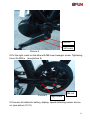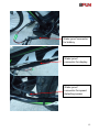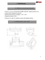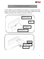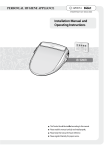
1
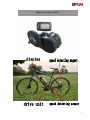
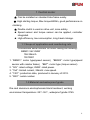
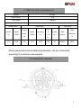
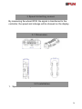
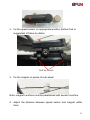
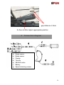
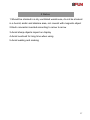
KIT CENTRAL 8
USER'S GUIDE
ENGLISH VERSION
Future Bike
www.future-bike.it
[email protected]
tel 0039 011 9699699
System composition
2
Catalog
1.1 Scope of application and numbering rule------------4
Central motor
1.2 Material and waterproof grade--------------------------4
1
1.3 Main technical parameters-------------------------------5
1.4 Installation diagram----------------------------------------5
1.5 Installation procedure-------------------------------------7
Display 2.1 Material and waterproof grade------------------------13
2 2.2 Dimension--------------------------------------------------13
2.3 Installation instruction-----------------------------------14
2.4 Button definition------------------------------------------15
2.5 Display Area-----------------------------------------------15
2.6 Power on---------------------------------------------------16
2.7 Adjust--------------------------------------------------------17
2.8 Parameter setting----------------------------------------20
2.9 Power off---------------------------------------------------22
2.10 Malfunction Code---------------------------------------22
Speed detecting
3.1 Installation dimension---------------------------------24
sensor 3
3.2 Installation-------------------------------------------------24
System connection
4 System connection diagram---------------------------26
diagram 4
Notes 5
After service &
warranty 6
Packing list 7
5 Notes---------------------------------------------------------27
6 After service & warranty-------------------------------28
7 Packing list-------------------------------------------------29
3
1 Central motor
★ Can be installed on standard bike frame easily.
★ High starting torque, Max torque≥80Nm, good performance on
climbing.
★ Double clutch is used on drive unit, more safety.
★ Speed sensor and torque sensor can be applied, controller
integrated.
★ High efficiency, low consumption, long travel mileage.
1.1 Scope of application and numbering rule
Countermark serial number on motor casing as following:
BBS01 36V 250W
15A 25km/h
13010001
1. “BBS01”: motor type(speed sensor);”BBS02”: motor type(speed
sensor with coaster brake);”BBT": motor type (torque sensor)
2. “36V”: rated voltage; 250W: rated power.
3. “15A”: limited current, 25km/h: max speed.
4. “1301”: production date, produced in January of 2013.
5. “0001”: serial number.
1.2 Material and waterproof grade
Die-cast aluminum electrophoresis black treatment, working
environment temperature:-25℃-55℃, waterproof grade: IP65.
4
1.3 Main technical parameters
Voltage
DC36V
Limit current
15A
Limit speed
25KM/H
Motor weight
3.7KG
no-load value
Rated value
Max value
torqu
Output
current
speed
(A)
(RPM)
power
(W)
MAX
speed
efficiency
e
current
MAX
(RPM)
(%)
(N
(A)
torque
≤9
≥80N.m
efficiency
(%)
m)
≤1.0
83±5
250
78±5
≥80%
≥30
≥80%
Above parameters as the default parameters, can be customized
according to customer requirements.
1.4 Installation diagram
5
6
Nut M33 nut
left crank
screw 2x M6*12
fixing plate
Self-tapping screw 5 x ST3.9
screw 5 x M5*10
Drive unit
chain wheel
right crank
chain cover
1.5 Installation procedure
1. Open the package and take out the drive unit and accessories;
And check the specification whether it is correct.
2. Fix the chain wheel on drive unit with 5pcs screw M5*10, (see
picture 1), then fix chain cover on chain wheel with 5pcs screw
ST3.9.
7
higher surface
5 x M5*10
lower surface
Picture1
3. Fix the drive unit axle tube on frame bottom bracket (see picture
2,picture 3)
Left
right
drive unit axle tube
Picture 2
8
Picture 3
ensure thread of axle tube extend
bottom bracket more than 10mm
4. The surface with teeth of fixing plate towards inside, then fix the
plate on drive unit with 2pcs M6*10.(see picture 4,picture 5)
the surface with teeth
of fixing plate
Picture 4
2xM6 nut
Outside surface
without teeth
Picture 5
9
5. Hold the drive unit near to bicycle fork, force less than 5KG, tight 1st
nut M33 onto axle tube with force:30-40N.m (see picture 6)
M33 nut
Picture 6
nd
6. Fix 2 nut M33 onto axle tube, tightening force:30-40N.m(see picture
7)
M33 nut
Picture 7
7.Fix the left crank on the bike with M8 inner hexagon screw. Tightening
force:35-40N.m (see picture 8)
10
M8 nut
left crank
Picture 8
8.Fix the right crank on the bike with M8 inner hexagon screw. Tightening
force:35-40N.m (see picture 9)
M8 nut
Picture 9
right crank
9.Connect all cables for battery, display, speed detecting sensor and so
on (see picture 10-12)
11
Water proof connector
for battery
Water proof
connector for display
Water proof
connector for speed
detecting sensor
12
2 C950 Display
2.1 Material and waterproof grade
Display’s casing use black/silver ABS materials, display window use
acrylic white transparent material.
Working temperature of display: - 20℃- 80℃.
Waterproof grade: IP65.
Ultrasonic is used for welding casing and display window.
2.2 Dimension (unit: mm)
13
2.3 Installation instruction
Fix the display onto the handlebar and adjust to an appropriate visual
angle, use a screw to fix the carrier onto bottom casing, then plug
display connector with controller connectors, that’s all.
Bottom casing
cable
Fixing slot
Fixing carrier
cable
Fixing carrier
3.3 用户设置概述
M3 screw
14
2.4 Button definition
C950 display is equipped with integrated buttons. The three buttons
are installed on the left side. The shape and location is as below:
System power switch
Mode selection, together with
for setting
back light switch, speed, mileage switch
2.5 Display Area
Display area includes battery capacity, riding mode, riding speed,
single riding distance, total riding distance, and malfunction code of
the electronic control system. Display area is as below:
15
Mode 1:walking assistant mode
Mode 2:economic mode
Mode 3:sports mode
Mode 4:power mode
2.6 Power on
First open the electric vehicle battery power.
Then press
to open system power(display below black font when
power on)
16
press
and choose favorite mode(refer to 2.7.1)
2.7 Adjustment
2.7.1 Mode selection
When e-bike power on, default mode is economic mode, press
0.5s to select mode, economic mode, sports mode and powerful
mode will be cyclic in order as following:
economic mode
sports mode
power mode
17
2.7.2 Walking Assistant
Hold
to enter walking assistant mode. The e-bike will go on at a
uniform speed below 6 KM/H. Release
, the e-bike goes back to
previous state, interface is as below:
Walking assistant mode
Warning:walking assistant function can only be used when the user is
pushing the e-bike. Please don’t use this function during riding.
2.7.3 Backlight turn On/Off
When the surrounding light is not enough or in the evening,turn on the
backlight. Hold
0.5s to switch on the backlight. Hold
0.5s
again to switch off the backlight.
2.7.4 Electric capacity display
When the battery capacity is overvoltage, the four battery segments
are all lighted and the battery display frame will flash. When the
18
battery capacity is normal, the four battery segments lighten
according to actual capacity. When the battery is under voltage, four
battery segments switch off and battery display frame will flash with
the frequency of 1 HZ, to remind user to recharge battery immediately.
2.7.5 Speed and mileage switch
When power on, display shows the current speed automatically. Hold
3s switch to total distance. Hold the
single riding distance. Hold
3s again switch to
3s again display will switch back to
current speed. Do this in turns and interface is as below:
current speed
19
total distance
single riding distance
2.8 Parameter setting
Parameter setting includes:wheel diameter setting(8inch~28inch)
and battery voltage setting(24V、36V).(The display is set already, do
not set it again except the user has special requirements.)
Put the power on,hold
and
together 3s to go the setting state,
the interface is as below:
2.8.1 Wheel size setting
Hold
0.5s to go into the wheel size setting state, hold
0.5s to
choose the right wheel size to make sure the speed and distance’s
20
accuracy. Wheel size includes 08、10、12、14、16、18、20、22、
26、28,choose in turn,interface is as below:
“"1":wheel size setting mode
"26":wheel size
2.8.2 Battery voltage setting
Hold
0.5s to go to voltage setting interface, hold
0.5s to choose
right voltage to make sure the display works normally. There are two
options of 24V and 36V, choose it in turn, interface is as below:
"2":voltage setting mode
"36":battery voltage
2.8.3 Single mileage reset
Press
0.5s to go into the single riding distance setting interface,
press
0.5s to clear the riding distance to zero, interface is as
21
below:
"3":riding distance reset
2.8.4 Exit the setting state
In the state of parameter setting, hold
and
for 3s to save the
current settings and exit the setting interface.
Attention: With no action for 5 seconds, it will exit the setting interface
automatically, and the adjustment will not be saved.
2.9 Power off
Hold
for 3 seconds to switch off display.
Power will be switch off automatically with no action of e-bike for 5
minutes.
Suggestion: Switch off the battery and storage it in a right way, if the
e-bike won’t be used.
2.10 Malfunction Code
If any errors appeared in electronic control system, the display will
show the error code automatically. For example:
22
"11": communication error
Note: The display can’t quit the malfunction code interface until the
malfunction is solved. The e-bike can not work when it is in
malfunction code display state.
No.
Code
1
02
2
03
3
4
5
04
05
06
6
07
7
08
8
09
9
10
10
11
11
12
Definition
chip system
abnormality
hall signal
abnormality
OVP
UVP
too hot on controller
over phase current
protection on motor
too hot on motor
throttle abnormality
/not connected
brake state
communication
abnormality
NTC abnormality on
motor
23
3 Speed detecting sensor
By measuring the wheel RPM, the signal is transferred to the
controller, the speed and mileage will be showed on the display.
3.1 Dimension
外观尺寸
外观尺寸
3.2 Installation
1. Speed sensor component
外观尺寸
外观尺寸
24
2. Fix the speed sensor on appropriate position (bottom fork is
suggested) of frame by ribbon.
tied by ribbon
3. Fix the magnet on spoke of rear wheel
Note: magnet's surface must be parallelized with sensor's surface
4. Adjust the distance between speed sensor and magnet within
5mm
25
gap distance ≤ 5mm
fix the nut after adjust appropriate position
4
Connection diagram
a) Brake sensor
b) Brake sensor
c) Display
d) Throttle
e) EB-BUS cable
f)
Battery
g) Speed detecting sensor
26
5 Notes
外观尺寸
1.Should be
stocked in a dry ventilated warehouse, do not be stocked
in a humid, acidic and alkaline area, not coexist with magnetic object
外观尺寸
2.Each connector inserted according to arrow to arrow
3.Avoid sharp objects impact on display
4.Avoid overload for long time when using
5.Avoid wading and soaking
27
6 After service and warranty
Suzhou
Bafang Electric Motor Science-Technology Co Ltd
外观尺寸
(hereinafter to be referred as “Bafang”) warrants that the products
bought from Bafang can be
provided service freely if the products are
外观尺寸
non-conformities in material and workmanship within warranty period.
Timing and scope of warranty: Warranty period starts from date of
Ex-factory, motor is within 30 months, controller, display, sensor and
other electric components is within 18 months.
Bafang limited warranty does not cover or apply to the following:
1) Damage, failure and/or loss caused by refitting, neglect,
improper maintenance, competition or commercial purpose,
misuse, abuse or accident;
2) Damage, failure and/or loss caused by shipping;
3) Damage, failure and/or loss caused by improper installation,
adjusting or repairing.
4) Damage, failure and/or loss irrelevant to material and
workmanship, e.g., failure to follow instructions by consumers;
5) Damage, failure and/or loss caused by product’s appearance
and surface change which doesn’t affect its function.
6) Damage, failure and/or loss caused by unauthorized service or
installation;
7) Damage, failure or loss caused by normal wear and tear.
Bafang reserves the right to repair the components or replace the
components, and is only responsible for repairing or replacing of the
products.
In case bike manufacturers or dealers encounter quality
problems when using or selling Bafang products, they can report the
purchase order number and products’ serial number to Bafang
technology service department who makes sure that if the products
are under warranty or not. If it is under warranty, Bafang will offer
repair or replacement for free. If it is out of warranty, Bafang still can
28
repair for customer, but the concerning material cost, labor cost,
freight etc. will be paid by customer.
If you have Bafang components on complete bikes need to be
repaired, please contact the bike manufacturer or dealer directly. If
this warranty statement is against to Chinese current law, the Chinese
law shall prevail. Bafang reserves the right to modify the terms without
any announcing in advance.
7 Packing list
Two sets system per carton with packing list:
1.BBS01 motor
2.display
3.brake
4.EB-BUS
5.fixing plate
6.chain wheel and chain cover
7.crank
8.M5*10 nut
9.M6*12 nut
10.M33 nut
11.ST 3.9 nut
12.speed detecting sensor
13.magnets
14.specification
2sets
2sets
2sets
2pcs
2pcs
2sets
2sets
10pcs
4pcs
4pcs
10pcs
2pcs
2pcs
2pcs
Above components list is for reference only, it can be changed with
different requirement.
29