1
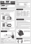
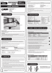
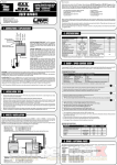
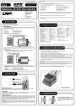
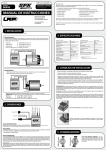
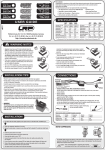
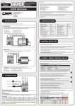
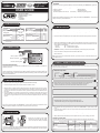
© LRP electronic GmbH 2007 RA00113 ORDER NO.: FORWARD/BRAKE OVER 6 TURNS 80800 USER GUIDE Dear customer, thank you for your trust in this LRP product. By purchasing a LRP IPC V8.1 GENERATION+ speed-control, you have chosen a high-performance speed-control. The new integrated V8.1 technology has even better driving feel and 25 (!) power maps for fine tuning. This speed-control is first choice for tough competition environments. Special highlights: • New V8.1 software • IceDrive Design • Optimised operation on 4 cells, w/o receiver battery • Launch Control • Digital Active Current Limiter • Multi-Protection-System LRP electronic GmbH Wilhelm-Enssle-Str. 132-134 73630 Remshalden Germany [email protected] www.LRP.cc • Advanced Digital • Improved brake feel • EPS Easy Programming System • Adjustable automatic- and initial-brake • 13AWG Power wires • Limited Lifetime Warranty Please read the following instructions to ensure, that your LRP IPC V8.1 GENERATION+ speed-control always works up to your full satisfaction. Please read and understand these instructions completely before you use this product! With operating this product, you accept the LRP warranty terms. 1. SPECIFICATION Forward/Brake Case Size Weight (excl. wires) Voltage Input Typical Voltage Drop* Rated Current* Rec. Motor Limit** B.E.C. yes 43x34x19mm 34g 4-8 cells (4.8-9.6V) @20A - 0.012V 480A over 6 Turns 5.8V * Transistors rating at 25°C junction temperature ** measured at 7.2V 4, 5, 6 cell optimised High Frequency IceDrive Design EPS Easy Programming System Improved Brake Feel Launch Control Digital Active Current Limiter Multi-Protection-System 13awg Power Wires yes yes yes yes yes yes yes yes yes Specifications subject to change without notice. • Mount the speedo using the supplied thick/black doubled-sided tape. • Connect the receiver connecting wire of the speed-control with the receiver (position: Channel 2). • Connect the speed-control to the motor: Red wire Connect to motor „Plus“ Blue wire Connect to motor „Minus“ CAUTION: Be careful with the correct polarity! • Doublecheck all connections before connecting the speed-control to a battery. CAUTION: If a battery is connected with reversed polarity it will destroy your speed-control! Motor - (Blue) Motor + (Red) • You can now switch on the speed-control with the On/Off switch. • The speed-control is now ready to be set-up (please see section 6 „Radio/speed-control set-up“ for further reference). brake FET-Servo wire blue On/Off Switch Receiver Connecting Wire For maximum performance, 13AWG power wires without any connectors are used for your LRP IPC V8.1 GENERATION+ speed-control. The motor power wires can be soldered directly to the motor. For the battery power wires we recommend to use reverse polarity protected plugs. • Solder some suitable plugs to the battery power wires (please also see section 2 „Connections“ for further reference). The plugs are not included with the speed-control. We recommend to use some reverse polarity protected plugs. Red wire Connect to battery „Plus“ Black wire Connect to battery „Minus“ 2. CONNECTIONS Battery + (Red) Battery - (Black) 5. INSTALLATION set RECEIVER CONNECTING WIRE: This LRP speed-control is equipped with a LRP Multicon receiver wire. As supplied, it will easily fit in all ordinary receivers. POWER WIRES: For maximum performance, 13AWG power wires without any connectors are used. The motor power wires can be soldered directly to the motor. For the battery power wires we recommend to use reverse polarity protected plugs. Nevertheless some soldering skills are required. Avoid soldering longer then 5sec per soldering joint to prevent possible damage due to overheating! (Please see section 5 „Installation“ for further reference) Note: If your servo has an external FET connection, you have to connect it to the blue FET servo wire of the speed-control. 6. RADIO / SPEED-CONTROL SET-UP In setup mode, the LRP IPC V8.1 GENERATION+ speed-control stores every step when you press the SET button. All the settings will be stored in the speed-controls memory even if the speed-control will be disconnected from the battery. TRANSMITTER SETTINGS Setup the following basic functions on your transmitter (if available): Throttle travel Brake travel Throttle exponential Neutral trim Servo reverse High ATV, EPA Low ATV, EPA, ATL EXP, EXPO SUB Trim Throttle reverse maximum maximum start with 0 centre any setting, don‘t change after set-up procedure! If your transmitter doesn‘t offer any of above functions, it‘s already in „basic setup“ mode. 3. INSTALLATION TIPS • Mount the speed-control using the supplied thick/black doubled-sided tape. • Position the speed-control where it is protected in the event of a crash. • Ensure that the speed-control is not connected to the drive battery and is switched off. • Remove motor pinion or ensure that the wheels of the model are free to rotate. • Switch the transmitter on and set the transmitter throttle stick to neutral. • Install the speed-control so that you have easy access to the connector and buttons. • Make sure there is enough clearance (about 3cm) between the speed-control, power-wires, antenna and receiver. Avoid any direct contact between power components, the receiver or the antenna. This can cause interference. If interference occurs, position the components at a different place in the model. • The aerial should be run vertically up and away from the receiver. Avoid contact with any parts made of carbon fibre or metal. If the aerial is too long, don’t coil up the excess length. It is better to cut it down to a length of about 35 cm. See also the instructions supplied with your radio control system. • Make sure there are enough cooling slits in the body. This will increase the performance and life of all the electronic components. HEATSINK: The supplied heatsink is not mandatory. But it improves and safeguards the performance capacity of your LRP IPC V8.1 GENERATION+ speed-control when used close to it‘s specified limits. Use only the genuine LRP IPC V8.1 GENERATION+ heatsink. Never allow the forward FETs or their heatsink to touch the brake FET or its heatsink. This will result in a short circuit! Racing motor Mabuchi motor 4. SUPPRESSION Motors with no capacitors or not enough capacitors may interfere with the speedcontrol. To avoid this, solder the supplied capacitors to your motor (see picture). The Schottky diode improves the efficiency of the speed-control/motor combination and provides extra protection to the brake FETs. Solder the diode in place as shown in the illustration. The white ring must always face the positive motor terminal. • Connect the speed-control to the battery and switch the unit on. • Hold the SET button pressed for at least 3sec using the supplied plastic screwdriver. You entered setup mode and the lower SET-LED flashes red (it will flash until the setup is completed). • Leave transmitter in neutral position and press the SET button once. Neutral setting is stored , the upper Brake-LED flashes green and the motor beeps. • Hold full throttle on transmitter and press the SET button once. Full-throttle setting is stored, the upper Brake-LED flashes red. • Hold full brake on transmitter and press the SET button once. Brake setting is stored, the upper Brake-LED and the lower SET-LED glow red. • This completes the setup procedure and your LRP IPC V8.1 GENERATION+ speed-control is ready to use. • If you have made a mistake so far, don’t worry: Switch off the speed-control for about 10 seconds and start over again. • After the run, first switch off the speed-control, unplug the battery and then switch off the transmitter. When you start again, first switch on the transmitter, then plug in the battery and switch on the speed-control. • Always disconnect the drive battery from the speed-control, if you are not using your model. CHECKING THE FUNCTIONS: Check the LED when moving your throttle stick and you will see if everything is setup correctly. FUNCTION Neutral with normal brake Neutral with automatic brake Forward Forward Brake Brake STATUS --partial throttle full throttle partial brake full brake LOWER SET-LED red off off red off red UPPER BRAKE-LED off red green green red red RA00112/RA00113 ! WARNHINWEISE © LRP electronic GmbH 2007 ! WARNING NOTES Kein Spielzeug. Nicht für Kinder unter 14 Jahren geeignet. No toy. Not suitable for children under 14 years. Bewahren Sie das Produkt außerhalb der Reichweite von kleinen Kindern auf. Keep the product out of the reach of children. Beachten Sie unbedingt die folgenden Hinweise, da diese Ihr Produkt zerstören können und die Gewährleistung ausschließen. Nichtbeachtung dieser Hinweise können zu Sach- und Personenschäden und schweren Verletzungen führen! • Lassen Sie das Produkt niemals unbeaufsichtigt, solange es eingeschaltet, in Betrieb oder mit einer Stromquelle verbunden ist. Im Falle eines Defekts könnte dies Feuer am Produkt oder seiner Umgebung verursachen. • Wickeln Sie Ihr Produkt niemals mit Plastikfolie, Metallfolie oder Ähnlichem ein, sondern sorgen Sie im Gegenteil für Frischluft. • Vermeiden Sie falschen Anschluss oder Verpolung des Produkts. • Alle Kabel und Verbindungen müssen gut isoliert sein. Kurzschlüsse können unter Umständen das Produkt zerstören. • Dieses Produkt oder andere elektronische Komponenten dürfen niemals mit Wasser, Öl, Treibstoffen oder anderen elektrisch leitenden Flüssigkeiten in Berührung kommen, da diese Mineralien enthalten können, die elektronische Schaltkreise korrodieren lassen. Bei Kontakt mit diesen Stoffen müssen Sie sofort den Betrieb einstellen und das Produkt sorgfältig trocknen. • Die Originalstecker und Originalkabel dürfen niemals verändert oder abgeschnitten werden. • Öffnen Sie niemals das Produkt und löten Sie keinesfalls auf der Platine oder anderen Komponenten • Benutzen Sie Ihr Produkt nicht mit geöffnetem, beschädigtem oder fehlendem Gehäuse oder in Schrumpfschlauch. Dies mindert den Störschutz, kann Kurzschlüsse verursachen und das Produkt beschädigen. • Entnehmen Sie immer den Akku aus Ihrem Produkt bzw. trennen Sie das Produkt von der Stromquelle, wenn das Produkt nicht verwendet wird. • Schalten Sie immer zuerst Ihren Sender ein, bevor Sie den Empfänger oder Fahrtenregler einschalten. Der Empfänger könnte Störsignale auffangen, Vollgas geben, und Ihr Modell beschädigen. Beim Ausschalten beachten Sie die umgekehrte Reihenfolge. Erst Empfänger und Fahrtenregler ausschalten, dann Sender ausschalten. • Solange der Motor an den Regler angeschlossen ist, dürfen Sie niemals den Motor mit einem separaten Akku oder mit einem Motor-Einlaufgerät laufen lassen. • Verändern Sie niemals die Polarität des Empfängersteckers. Pay close attention to the following points, as they can destroy the product and void your warranty. Non-observance of these points can lead to property damage, personal and severe injuries! • Never leave the product unsupervised while it is switched on, in use or connected with a power source. If a defect occurs, it could set fire to the product or the surroundings. • Never wrap your product in plastic film, metal foil or similar. In fact, make sure it gets enough fresh air. • Avoid incorrect connections or connections with reversed polarity of the product. • All wires and connections have to be well insulated. Short-circuits can possibly destroy the product. • Never allow this product or other electronic components to come in contact with water, oil or fuels or other electroconductive liquids, as these could contain minerals, which are harmful for electronic circuits. If this happens, stop the use of your product immediately and let it dry carefully. • Never cut off or modify the original plugs and original wires. • Never open the product and never solder on the PCB or other components. • Never use this product when the case is open, damaged or missing or when the product is wrapped in a shrink-fit tube. This will reduce protection, may cause short circuits and damage the product. • Always remove the battery from your product or disconnect the product from the power source, if the product is not in use. • Always switch on your transmitter first before you switch on the receiver or the speed control. The receiver could receive interference signals, start full acceleration and damage your model. When you switch off, make sure you do so in the reverse sequence. First switch off the receiver and speed control, then switch off the transmitter. • If the speed-control is connected to the motor, never run the motor directly with a separate battery or run-in device. • Never change the polarity of the receiver connector. • Always wire up all the parts of the equipment carefully. If any of the connections come loose as a result of vibration, you could loose control over your model. • Schließen Sie sämtliche Teile der Ausrüstung sorgfältig an. Falls sich die Verbindungen durch Vibrationen lösen, können Sie die Kontrolle über das Modell verlieren. Das Symbol einer durchgestrichenen Abfalltonne auf Rädern bedeutet, dass das Produkt in der Europäischen Union einer getrennten Müllsammlung zugeführt werden muss. Diese Produkte dürfen nicht über den unsortierten Hausmüll entsorgt werden. The crossed-out wheeled bin means that within the European Union the product must be taken to seperate collection at the product end-of-life. Do not dispose of these products as unsorted municipal waste. 7. SPECIAL FEATURES 10. TROUBLESHOOTING GUIDE Launch Control: The LRP IPC V8.1 GENERATION+ Launch Control gives you a crucial advantage at the start of a race. In this mode the response time of the speed-control is shortened (half-throttle on the transmitter corresponds to full-throttle on the speed-control) and the set current limiting value is doubled for the start of the race. The first time you reduce throttle (first turn) the LRP IPC V8.1 GENERATION+ speed-control automatically reverts to the normal racing program. Activating the Launch Control: Hold trigger of transmitter at full brake for 5sec before start. Ready and active!!! Improved Brake Feel: The LRP IPC V8.1 GENERATION+ speed-control features a fully proportional brake which can be applied very smoothly to maintain good grip on slippery surfaces. Thanks to the Advanced Digital technology, it was possible to improve the brake feel of the LRP IPC V8.1 GENERATION+ speed-control even more. Advantages: • Smooth, proportional braking • Superior braking power • Battery recharge during braking If the braking power is too strong for your driving style and conditions, you can reduce it by adjusting servo travel at the transmitter. Forward/Brake: Uncompromising and outstanding performance for top level competition was the target! Therefore the LRP engineering team developed a pure forward/brake competition speed-control without reverse function. IceDrive Design: LRP’s secret IceDrive Design results in lower speedo temperature under all racing conditions. Sorry, no further details to be disclosed. Simply a step ahead of the competition! Multi-Protection System, 3-way protection: The perfect protection against short-circuits (motor), overload and overheating. If your speed-control faces one of these problems, the motor function will be shut-off for protection and the LED will flash. The steering function will be maintained. Let everything cool down for a few minutes. If the speed-control switches off frequently, either the used motor is too strong, the motor pinion is too big or you are using full brake too often. You can improve this if you make additional cooling slots in the body. SYMPTOM CAUSE REMEDY Servo is working, no motor function. Speed-control plugged in incorrectly Plug speed-control in Ch 2 Overload protection activated Allow speed-control to cool down Wiring problem Check wires and plugs Motor defective Replace motor Motor brushes stuck Check that brushes are moving freely Speed-control defective Send in product for repair Speed-control plugged in incorrectly Plug speed-control in with correct polarity Crystal defective Replace components one by one. No servo and no motor function. Receiver defective Transmitter defective Speed-control defective Send in product for repair Motor runs in reverse when accelerating forward on the transmitter. Motor connected incorrectly Connect motor correctly Insufficient performance. E.g. poor brake power, topspeed or acceleration.. Motor pinion too big or gear ratio too long. Use smaller motor pinion/shorter gear ratio Transmitter settings changed after set-up Repeat set-up procedure Motor worn out Maintain motor Motor defective Replace motor Speed-control defective. Send in product for repair Motor stronger than motorlimit or input voltage too high Use only motors and batteries which are within the specifications of the speed-control Motor pinion too big or gear ratio too long. Use smaller motor pinion/shorter gear ratio Drive train or bearing problems. Check or replace components. Model used too often without cool-down periods Let speed-control cool down after every run Transmitter settings changed after set-up Repeat set-up procedure Humidity/water in speed-control Immediately unplug and dry speed-control Speed-control defective Send in product for repair Motor suppressors not sufficient Solder capacitors to motor Receiver or antenna too close to power wires, motor, battery or speed-control. Receiver aerial too short or coiled up See „Installation Tips“ and „Installation“ Receiver defective, too sensitive; Transmitter defective, transmitter output power too low, servo problem Replace components one by one Only use original manufacturers crystals Poor battery connection Check plugs and connecting wires Transmitter batteries empty Replace / recharge transmitter batteries Transmitter antenna too short Pull out antenna to full length Receiver problem (especially with some 2.4GHz systems) Use a power capacitor on the receiver Speed-control overheats or switches off frequently. Motor never stops, runs at constant slow speed Radio interference 8. BRAKE ADJUSTEMENT Normal brake: standard characteristics (for normal to slippery conditions): Rotate the brake potentiometer fully to the left. This produces a linear braking effect over the full stick travel, and provides perfect vehicle control during braking. Soft brake (for extremely slippery surfaces): Rotate the brake potentiometer fully to the left. If you still need a reduction in braking power, use the LOW ATV, EPA or ATL function (reduced brake travel) on your transmitter to reduce the braking power. Aggressive „hand-brake“: Turn the brake potentiometer to the right. This allows you to control your vehicle aggressively and throw it around corners. Turn the brake potentiometer to the right and the brake becomes more aggressive; turn it to the left and it becomes more gentle. Note that maximum braking power is unchanged regardless of the position of the brake potentiometer. If you wish to adjust overall braking power you should reduce the travel of the brake function on your transmitter. Automatic brake: As soon as you move the throttle stick to neutral, the speed-control brakes automatically, which allows even tighter turns. You can adjust the power of the automatic brake at neutral to any setting within the range of 1% (brake potentiometer fully left) and 60 % (brake potentiometer fully right). The maximum braking power will not be affected. Switching the brake programs: Applies if you change from normal to automatic brake and vice versa: Switch speed-control off --> Press and hold SET button --> Switch speed-control on (while SET button is pressed!) --> Brake programm changed. The chosen brake programm can be determined by the status of the LEDs (see „CHECKING THE FUNCTIONS“ in section 6). 9. DIGITAL ACTIVE CURRENT LIMITER The LRP IPC V8.1 GENERATION+ speed-control can be adjusted to meet the exact requirements of your model and the track. To activate current limiting you must install one of the plug-in chips (supplied in the values of 30A, 50A, 65A, 80A and 120A) or the infinitely variable limiter potentiometer (#8110). Without one of the chips or the limiter potentiometer fitted, maximum power is always available and the current limiting is not active. • The orientation of the plug-in chip determines the power program which is activated (see illustration). As soon as you open the throttle, the basic current limiting value (value on the chip) is in force, and after a defined period of acceleration (selected with the power program) the speed-control intelligently increases the maximum current, and repeats the process every time you resume acceleration. • The various programs represent a method of fine-tuning the speed-control’s response. The LRP IPC V8.1 GENERATION+ always provides a linear characteristic curve and superior battery efficiency, regardless of the program you choose. Start with the following settings: Racing Class 2WD Truck 4WD Pro 10 1/12 Touring Car Current Limiter 65A 80A 80A 65A 50A 80A Current Limiter Programs: Power Programm 2 3 3 3 2 3 Program 1 2 3 4 Acceleration Driveability O OO OOO OOOO 0000 000 00 0 Battery Efficiency 0000 Very gentle 000 Gentle 00 Power+Efficiency 0 Max. Power Programming with chips: Example: Chip 65 Ampere Power programm #3 Programming with limiter potentiometer: (#8110) The limiter potentiometer also provides 4 program settings and additionally a variable current limiting within the range of 0 - 100 Ampere. Speed-control looses settings REPAIR PROCEDURES / LIMITED WARRANTY All products from LRP electronic GmbH (hereinafter called “LRP”) are manufactured according to the highest quality standards. LRP guarantees this product to be free from defects in materials or workmanship for 90 days (non-european countris only) from the original date of purchase verified by sales receipt. This limited warranty doesn’t cover defects, which are a result of normal wear, misuse or improper maintenance. This applies among other things on: • • • • • • • Cut off original power plug or not using reverse polarity protected plugs Receiver wire and/or switch wire damaged Mechanical damage of the case Humidity/Water inside the speed-control Mechanical damage of electronical components/PCB Soldered on the PCB (except on external solder-tabs) Connected speed-control with reversed polarity To eliminate all other possibilities or improper handling, first check all other components and the trouble shooting guide, if available, before you send in this product for repair or warranty. Products sent in for repair, that operate perfect have to be charged with a service fee. By sending in this product, you assign LRP to repair the product, if it is no warranty or Limited Lifetime Warranty case. The original sales receipt including date of purchase needs to be included. Otherwise, no warranty can be granted. For quick repair- and return service, add your address and detailed description of the malfunction. Because we don’t have control over the installation or use of this product, we can‘t accept any liability for any damages resulting from using this product. Therefore using this product is at owner‘s risk. Our limited warranty liability shall be limited to repairing the unit to our original specifications. In no case shall our liability exceed the original cost of the unit. By installing or operating this product, the user accepts all resulting liability. The specifications like weight, size and others should be seen as guide values. Due to ongoing technical improvements, which are done in the interest of the product, LRP does not take any responsibility for the accuracy of these specs. With Limited Lifetime Warranty products, the warranty terms on the Limited Lifetime Warranty card do also apply. LRP-Distributor-Service: • Package your product carefully and include sales receipt and detailed description of malfunction. • Send parcel to your national LRP distributor. • Distributor repairs or exchanges the product. • Shipment back to you usually by COD (cash on delivery), but this is subject to your national LRP distributor‘s general policy.