1
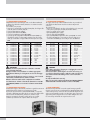
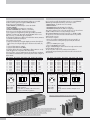
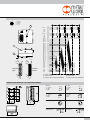
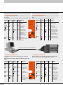
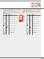
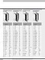
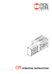
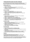
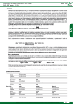
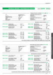
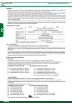
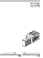
MANUALE D’USO
OPERATING INSTRUCTIONS
I
GB
1. INSTALLAZIONE E COLLEGAMENTI ELETTRICI
1. INSTALLATION AND ELECTRICAL CONNECTIONS
1.1 COLLEGAMENTO CLEVER CENTER
L’alimentazione ed il comando degli out di un isola Clever Multimach
si effettua sul modulo Clever Center, attraverso un connettore maschio
D-Sub 44 poli.
Sul connettore sono presenti:
•32 pin per il comando delle 32 valvole (elettropiloti), da collegare alle
uscite del sistema di controllo, PLC, PC…
•3 pin per l’alimentazione +24Vdc;
•3 pin per l’alimentazione 0V (GND);
•1 pin per la segnalazione guasto (Out DIAG);
•1 pin (39) per la configurazione PNP/NPN del sistema (CFG). Per
comandare le valvole con logica PNP, connettere il pin 39 a quello
+24V; per comandarle con logica NPN connettere il pin 39 a quello
GND.
PIN
1
2
3
4
5
6
7
8
9
10
11
12
13
14
15
Funzione
Comando EV1
Comando EV2
Comando EV3
Comando EV4
Comando EV5
Comando EV6
Comando EV7
Comando EV8
Comando EV9
Comando EV10
Comando EV11
Comando EV12
Comando EV13
Comando EV14
Comando EV15
PIN
16
17
18
19
20
21
22
23
24
25
26
27
28
29
30
Funzione
Comando EV16
Comando EV17
Comando EV18
Comando EV19
Comando EV20
Comando EV21
Comando EV22
Comando EV23
Comando EV24
Comando EV25
Comando EV26
Comando EV27
Comando EV28
Comando EV29
Comando EV30
PIN
31
32
33
34
35
36
37
38
39
40
41
42
43
44
Funzione
Comando EV31
Comando EV32
Out guasto DIAG
Riservato
Riservato
+24 Vdc
+24 Vdc
+24 Vdc
In. config. CFG
Riservato
Riservato
GND
GND
GND
PIN
1
2
3
4
5
6
7
8
9
10
11
12
13
14
15
Function
EV1 control
EV2 control
EV3 control
EV4 control
EV5 control
EV6 control
EV7 control
EV8 control
EV9 control
EV10 control
EV11 control
EV12 control
EV13 control
EV14 control
EV15 control
PIN
16
17
18
19
20
21
22
23
24
25
26
27
28
29
30
Function
EV16 control
EV17 control
EV18 control
EV19 control
EV20 control
EV21 control
EV22 control
EV23 control
EV24 control
EV25 control
EV26 control
EV27 control
EV28 control
EV29 control
EV30 control
PIN
31
32
33
34
35
36
37
38
39
40
41
42
43
44
Function
EV31 control
EV32 control
Output faulty DIAG
Reserved
Reserved
+24 Vdc
+24 Vdc
+24 Vdc
In CFG config.
Reserved
Reserved
GND
GND
GND
ATTENZIONE
Disattivare la tensione prima di inserire o disinserire i connettori
(pericolo di danni funzionali).
Collegare il modulo a terra, mediante un conduttore appropriato.
Eventualmente utilizzare per il collegamento uno dei fori di fissaggio
libero.
La mancanza di collegamento a terra può causare, in caso di scariche
elettrostatiche, malfunzionamenti e danni irreversibili.
WARNING
Power off the system before plugging in or unplugging the connectors
(risk of functional damages).
Connect the module to earth using the correct wire. If necessary, use
one of the free fixing holes. Failure to make the earth connection may
cause faults and irreversible damages in the event of electrostatic
discharges.
Utilizzare solamente unità di valvole completamente assemblate.
Only use power packs complying with the IEC 742/ EN60742/VDE0551
standard and with a minimum insulation resistance of 4kV (PELV).
Per l’alimentazione utilizzare esclusivamente alimentatori a norma IEC
742/ EN60742/VDE0551 con resistenza di isolamento minima di 4kV
(PELV).
1.2 COLLEGAMENTO ALLE VALVOLE
Il terminale di ingresso, Clever Center, trasforma i segnali che arrivano in
parallelo dai pin del connettore in una trasmissione seriale.
Il protocollo di comunicazione seriale Metal Work CM, si occupa del
comando e della diagnostica delle valvole. La connessione elettrica delle
valvole avviene automaticamente, attraverso il connettore 9 poli
integrato, avvicinando e fissando le valvole tra loro. E’ possibile
connettere più valvole fino al completo utilizzo dei 32 output.
2
1.1 CLEVER CENTER CONNECTION
The outputs of the array of Clever Multimach valves are powered and
controlled by the Clever Center module via a D-Sun 44-pin male
connector.
The connector has:
•32 pins for controlling the 32 valves (solenoid pilots), to be connected
to the control system inputs, the PLC, PC and other utilities…
•3 pins for +24 Vdc power supply;
•3 pins 0V (GND) power supply;
•1 pin for fault signals (Out DIAG);
•1 pin (39) PNP/NPN configuration of the system (CFG). To control
the valves with PNP logic, connect the pin 39 to the +24V one; to control them with NPN logic connect the pin 39 to the GND one.
Use fully assembled valve units only.
1.1 VALVE CONNECTION
Clever Center input terminal converts the signals arriving in parallel
from the connector pin into a serial transmission. Metal Work CM serial
communication protocol controls the valves and handles diagnostics. The
valves are automatically powered on via the built-in 9-pin connector, by
approaching and securing the valves one another. Multiple valves can
be connected up until all the 32 outputs have been used.
1.3 COLLEGAMENTO AI MODULI SLAVE
Il collegamento ai moduli Slave avviene con un connettore M8 4 poli,
che provvede sia all’alimentazione elettrica che al comando delle
valvole, attraverso il protocollo di comunicazione seriale Metal Work,
CM.
E’ possibile collegare in serie più isole slave fino al completo utilizzo dei
32 output.
1.3 SLAVE MODULE CONNECTION
The Slave modules can be connected using an M8 4-pin connector,
which feeds the valves and controls them via Metal Work CM serial
communication protocol.
Multiple slave module arrays can be connected up until all the 32 outputs
have been used.
1.4 TERMINAZIONE DELLA LINEA
Per un corretto funzionamento, è necessario terminare la linea seriale.
La linea delle valvole si termina automaticamente chiudendo il pacco
valvole con il terminale cieco. La linea di collegamento alle isole slave, si
termina inserendo l’apposito terminatore M8 nel connettore M8 femmina
del Clever Center se non ci sono isole Slave, oppure al connettore
dell’ultima isola Slave della rete. In caso di mancato inserimento del
terminatore, viene generata una segnalazione di bus interrotto.
1.4 SERIAL LINE COMPLETION
For correct operation, the serial line needs to be completed. The valve
line is completed automatically by closing the array of valves with a blind
terminal. The line connecting the slave modules is completed by inserting
the M8 terminal into the M8 female connector of the Clever Center if
there are no slave modules, or to the connector of the last slave module
in the network. If the terminal is not inserted, a bus-interrupted signal will
be generated.
1.5 CONFIGURAZIONE DELLE USCITE
Non è necessario eseguire l’indirizzamento dei moduli slave.
All’accensione, alle valvole connesse, viene attribuita automaticamente
una numerazione sequenziale, a partire dalla prima collegata al modulo
Clever Center fino all’ultima valvola collegata all’ultimo slave della rete.
Le valvole monostabili occupano 1 output, le valvole bistabili occupano
2 output.
1.5 OUTPUT CONFIGURATION
The slave modules need not to be addressed. The connected valves are
automatically assigned a number on start-up, from the first valve
connected to the Clever Center module to the last one connected to the
slave module in the network.
Monostable valves require 1 output, bistable valves 2 outputs.
Collegamento seriale / Serial connection
EV15
EV16/EV17
EV18
EV19
EV...32
EV1
EV2
EV3
EV4
EV5/EV6
EV7
EV8/EV9
EV10/EV11
EV12
EV13
EV14
Terminatore / Terminator
M8
M8
Slave 1
Slave 2
Clever Center
Cavo multipolare 44 PIN, fino a 32 OUTPUT / 44-pin multi-core cable, max 32 outputs
ATTENZIONE
In caso di modifiche alla configurazione delle isole, la numerazione
delle valvole viene automaticamente aggiornata.
WARNING
If the array configuration is modified, valve numbering will
automatically be updated.
3
2. COLLEGAMENTO DEI MODULI INPUT/OUTPUT
2. INPUT/OUTPUT MODULE CONNECTION
Scegliendo il Clever Center appositamente predisposto è possibile
inserire moduli di gestione di segnali di INPUT/OUTPUT.
Essi possono essere impiegati per:
• INPUT DIGITALI, quali ad esempio i sensori dei cilindri
• OUTPUT DIGITALI
• INPUT ANALOGICI (ma i LED non si accendono)
• OUTPUT ANALOGICI (ma i LED non si accendono)
Essi possono essere mescolati, anche sullo stesso modulo.
Si può scegliere tra collegamenti tipo PNP oppure NPN, impostando
mediante un selettore tipo DIP switch. Tutti gli IN/OUT devono essere
dello stesso tipo, cioè tutti PNP oppure tipo NPN.
Il collegamento degli input si effettua sul modulo Clever Center, attraverso
un connettore femmina D-Sub 44 poli.
Sul connettore sono presenti:
•32 pin per la lettura dei 32 segnali digitali provenienti dai moduli di
input connessi, da collegare agli ingressi del sistema di controllo, Plc,
PC…
•3 pin per l’alimentazione +24Vdc,
•3 pin per l’alimentazione 0V (GND).
La selezione del tipo di ingresso, PNP/NPN si effettua attraverso un dip
switch alloggiato sotto il coperchio del modulo Master.
Non è necessario eseguire l’indirizzamento dei moduli Input. L’indirizzo
viene attribuito automaticamente a partire dal primo modulo collegato al
Clever Center.
PIN
1
2
3
4
5
6
7
8
9
Funzione
Input 1
Input 2
Input 3
Input 4
Input 5
Input 6
Input 7
Input 8
Input 9
PIN
10
11
12
13
14
15
16
17
18
Funzione
Input 10
Input 11
Input 12
Input 13
Input 14
Input 15
Input 16
Input 17
Input 18
PIN
19
20
21
22
23
24
25
26
27
Funzione
Input 19
Input 20
Input 21
Input 22
Input 23
Input 24
Input 25
Input 26
Input 27
PIN
28
29
30
31
32
33
34
35
36
Funzione
Input 28
Input 29
Input 30
Input 31
Input 32
NC
NC
NC
+24 Vdc
PIN
37
38
39
40
41
42
43
44
By choosing the specially designed Clever Center you can add INPUT/
OUTPUT signal management modules, wich can be used for:
• DIGITAL INPUTS, as cylinder sensors for example
• DIGITAL OUTPUTS
• ANALOGUE INPUTS (but the LEDs do not light up)
• ANALOGUE OUTPUTS (but the LEDs do not light up)
They can be combined, even on the same module. You can choose between PNP or NPN connections via a dip switch-type selector.
All the INPUTS/OUTPUTS must be the same type, i.e. all PNP or NPN.
The inputs are connected on the Clever Center module using a D-Sub
44-pin female connector.
The connector comprises:
•32 pins for reading 32 digital signals from the input modules, to
be connected to the control system inputs, the PLC, PC and other
utilities...
•3 pins for +24VDC power supply
•3 pins for 0V (GND) power supply
The type of PNP/NPN input can be selected via a dip switch mounted
below the Master module cover.
The input modules need not to be addressed. The address is
automatically assigned starting from the first module connected to the
Clever Center.
Funzione
+24 Vdc
+24 Vdc
NC
NC
NC
GND
GND
GND
Connettore M8 3 poli Selezione tipo di ingresso PNP Selezione tipo di ingresso NPN
4
3
ON
OFF
PIN
10
11
12
13
14
15
16
17
18
M8 3-pin connector
4
SW1
3
PIN
19
20
21
22
23
24
25
26
27
Function
Input 19
Input 20
Input 21
Input 22
Input 23
Input 24
Input 25
Input 26
Input 27
PIN
28
29
30
31
32
33
34
35
36
PNP INPUT type selection
PIN
37
38
39
40
41
42
43
44
ON
SW1
OFF
OFF
50-pin connector
If the 2 dip switches are both OFF, the indicator lights do not
come on.
If the 2 dip switches are both ON, all the lights come on
together.
Selezione tipo di ingresso PNP-NPN / Input type selection PNP-NPN
IN 8
IN 7
Modulo input-output 1 (1÷8) / Input-output module 1 (1÷8)
Modulo input-output 2 (9÷16) / Input-output module 2 (9÷16)
Modulo input-output 3 (17÷24) / Input-output module 3 (17÷24)
Modulo input-output 4 (25÷32) / Input-output module 4 (25÷32)
4
Function
+24 Vdc
+24 Vdc
NC
NC
NC
GND
GND
GND
NPN INPUT type selection
50-pin connector
Pin 1 = +24 Vdc
Pin 3 = GND
Pin 4 = Input
Function
Input 28
Input 29
Input 30
Input 31
Input 32
NC
NC
NC
+24 Vdc
SW1
1
Connettore 50 poli
Se i 2 dip switch sono entrambi su OFF non si ha l’accensione
dei LED di segnalazione.
Se i 2 dip switch sono entrambi su ON si ha l’accensione
contemporanea di tutti LEDs di segnalazione.
Function
Input 10
Input 11
Input 12
Input 13
Input 14
Input 15
Input 16
Input 17
Input 18
ON
OFF
Connettore 50 poli
Pin 1 = +24 Vdc
Pin 3 = GND
Pin 4 = Input
Function
Input 1
Input 2
Input 3
Input 4
Input 5
Input 6
Input 7
Input 8
Input 9
ON
SW1
1
PIN
1
2
3
4
5
6
7
8
9
IN 1 IN 2
SCHEMA COLLEGAMENTO INPUT / INPUT CONNECTION DIAGRAM
2
1
4
3
1 = RTX +
2 = GND
3 = RTX 4 = Vcc
3
0 Vdc
NC
NC
NC
+24 Vdc
1
2
1
16
15
30
44
31
maschio
MALE
femmina
FEMALE
44
30
31
16
15
1
NC
NC
NC
IN 32
IN 31
IN 30
IN 29
IN 28
IN 27
IN 26
IN 25
IN 24
IN 23
IN 22
IN 21
IN 20
IN 19
IN 18
IN 17
IN 16
IN 15
IN 14
IN 13
IN 12
IN 11
IN 10
IN 9
IN 8
IN 7
IN 6
IN 5
IN 4
IN 3
IN 2
IN 1
44
43
42
41
40
39
38
37
36
35
34
33
32
31
30
29
28
27
26
25
24
23
22
21
20
19
18
17
16
15
14
13
12
11
10
9
8
7
6
5
4
3
2
1
PIN 1 PIN 3 PIN 1 PIN 3 PIN 1 PIN 3 PIN 1 PIN 3
X1...X8 X1...X8 X1...X8 X1...X8 X1...X8 X1...X8 X1...X8 X1...X8
X8
X7
X6
X5
X4
X3
X2
X1
X8
X7
X6
X5
X4
X3
X2
X1
a Led di segnalazione
b Messa a terra
c Selettore tipo di ingresso PNP/NPN
X8
X7
X6
X5
X4
X3
X2
X1
X8
X7
X6
X5
X4
X3
X2
X1
a Indicator LED
b Grounding
c Input selector type PNP/NPN
MODULO 8 INPUT-OUTPUT M8 / M8 8-INPUT-OUTPUT MODULE
INPUT PNP
1 = + 24 VDC 3 = OVDC 4 = INPUT
INPUT NPN
1 = + 24 VDC 3 = OVDC 4 = INPUT
OUTPUT PNP
1 = + 24 VDC 3 = OVDC 4 = INPUT
OUTPUT NPN
1 = + 24 VDC 3 = OVDC 4 = INPUT
DIP SWITCH
DIP SWITCH
OUTPUT ANALOGICO
OUTPUT ANALOGIC
INPUT ANALOGICO
INPUT ANALOGIC
5
3. DIAGNOSTICA
3.1 DIAGNOSTICA CLEVER CENTER
La diagnostica del modulo Clever Center, è definita dallo stato dei LEDs
di interfaccia.
La generazione di un allarme, attiva la segnalazione di guasto Out DIAG.
3.1 CLEVER CENTER DIAGNOSTICS
Clever Center module diagnostics is defined by the status of the interface
lights.
When an alarm is generated, and Out DIAG fault is indicated.
LED Verde LED Rosso LED Rosso OUT SIGNIFICATO
Power ON BUS error LOCAL error DIAG
Green power Red BUS Red local OUT MEANING
ON light error light error light DIAG
Power
VERDE OFF
OFF
ON
(lampeggiante)
ON (verde) OFF
ROSSO ON
(lampeggiante)
Numero di valvole
collegate alla rete
maggiore di 32.
Elettropilota interrotto o in corto circuito su elettrovalvola collegata
al modulo Clever Center.
Linea seriale di
collegamento delle
elettrovalvole al modulo Clever Center interrotta.
ON (verde) ROSSO OFF
ON
(lampeggiante) Linea seriale di
collegamento a un modulo
slave successivo interrotta
o non terminata.
ON (green) OFF OFF
OFF The module is
operating correctly.
Bus Error
Local Error
GREEN OFF
OFF
ON
(flashing)
ON (green)
OFF
RED ON
(flashing)
Number of valves
connected to the
network greater than 32.
Solenoid pilot interrupted
or short-circuit on the
solenoid valve connected to
the Clever Center module.
Serial line linking the
solenoid valve to the Clever
Center module interrupted.
82/84
ADE IN ITALY
ON (verde) OFF OFF
OFF Il modulo funziona
correttamente.
3. DIAGNOSTICS
1
3/5
11
ON (green)
RED OFF
ON Serial line connecting to a
(flashing)
subsequent slave module
interrupted or not completed.
segnale di errore OUT DIAG / Error signal OUT DIAG
3.2 DIAGNOSTICA MODULI SLAVE
La diagnostica dei moduli Slave, è definita dallo stato dei LEDs di
interfaccia.
La generazione di un allarme, attiva la segnalazione di guasto Out
DIAG.
LED Verde LED Rosso LED Rosso OUT
Power ON BUS error LOCAL error DIAG
SIGNIFICATO
ON (verde) OFF OFF
OFF Il modulo funziona
correttamente.
ROSSO
Power
ON
Elettropilota interrotto
(lampeggiante) (intermittente)o in corto circuito su
elettrovalvola collegata
al modulo.
ON (verde) OFF
ROSSO ON
(lampeggiante)
Linea seriale di
collegamento delle elettrovalvole al modulo
interrotta.
ON (verde) ROSSO OFF
ON
(lampeggiante) Linea seriale di
collegamento a un
modulo slave successivo
interrotta o non terminata.
Linea seriale Clever
Center interrotta.
6
Bus Error
Local Error
82/84
1
3/5
11
Green powerRed BUS Red local OUT
ON light
error light error light DIAG
MEANING
ON (green) OFF OFF
OFF The module is
operating correctly.
ON (green) OFF
RED
ON
Solenoid pilot (flashing)
(intermittent) interrupted or short
circuit on the solenoid valve connected
to the module.
ADE IN ITALY
ON (verde) OFF
3.2 SLAVE MODULE DIAGNOSTICS
Slave module diagnostics is defined by the status of the interface lights.
When an alarm is generated, and Out DIAG fault is indicated.
ON (green) OFF
RED ON
(flashing)
Serial line connecting
the solenoid valve to
the module interrupted.
ON (green) RED OFF
ON
(flashing)
Serial line connecting
to a subsequent slave
module interrupted
or not completed.
Center Clever serial
line interrupted.
3.3 DIAGNOSTICA MODULI VALVOLA
La diagnostica dei moduli valvola, è definita dallo stato dei LEDs di
interfaccia.
La generazione di un allarme, attiva la segnalazione di guasto Out
DIAG su Clever Center.
3.3 VALVE MODULE DIAGNOSTICS
Valve module diagnostics is defined by the status of the interface lights.
When an alarm is generated, and Out DIAG fault is indicated on clever
center.
LED 14
LED 12
SIGNIFICATO
LED 14
LED 12
MEANING
OFF OFF
Nessuna anomalia, EV1-EV2 = OFF
OFF OFF
No fault, EV1-EV2 = OFF
LED 12
ON (verde) OFF
Nessuna anomalia, EV1 = ON - EV2 = OFF
ON (verde) ON (verde) Nessuna anomalia, EV1-EV2 = ON
LED 14
ON (green) OFF
No fault, EV1 = ON - EV2 = OFF
ON (green) ON (green) No fault, EV1-EV2 = ON
OFF ON (verde) Nessuna anomalia, EV1 = OFF - EV2 = ON
OFF ON (green) No fault, EV1 = OFF - EV2 = ON
ROSSO OFF
Elettropilota EV1 interrotto e scollegato
RED (flashing)
OFF
Solenoid pilot EV1 interrupted or
disconnected
OFF ROSSO
Elettropilota EV2 interrotto e scollegato
OFF RED
(flashing)
Solenoid pilot EV2 interrupted or
disconnected
ON (red)
OFF
Solenoid pilot EV1 short circuit
(lampeggiante)
(lampeggiante)
ON (rosso) OFF
Elettropilota EV1 in cortocircuito
OFF ON (rosso) Elettropilota EV2 in cortocircuito
OFF ON (red)
Solenoid pilot EV2 short circuit
VERDE
OFF
(lampeggiante)
GREEN
OFF
(flashing)
Data update time out,
communication faulty
Time out aggiornamento dati,
comunicazione difettosa.
7
4. COLLEGAMENTO CAVO PRECABLATO
44 POLI FEMMINA PRECABLATO
PER VALVOLE
44 POLI MASCHIO PRECABLATO
PER INPUT/OUTPUT
44 PIN FEMALE PRE-WIRED
FOR VALVE
44 PIN MALE PRE-WIRED
FOR INPUT/OUTPUT
31
16
1
16
31
16
1
16
1
31
1
31
15
44
15
44
30
30
30
30
44
15
44
15
PIN Colore conduttore
corrispondente
1
bianco
2
marrone
3
verde
4
giallo
5
grigio
6
rosa
7
blu
8
viola
9
grigio/rosa
10 rosso/blu
11 bianco/verde
12 marrone/verde
13 bianco/giallo
14 giallo/marrone
15 bianco/grigio
16 grigio/marrone
17 bianco/rosa
18 rosa/marrone
19 bianco/blu
20 marrone/blu
21 bianco/rosso
22 marrone/rosso
23 bianco/nero
24 marrone/nero
25 grigio/verde
26 giallo/grigio
27 rosa/verde
28 giallo/rosa
29 verde/blu
30 giallo/blu
31 verde/rosso
32 giallo/rosso
33 verde/nero
8
4. PRE-WIRED CABLE CONNECTION
34
35
36
37
38
39
grigio/blu
grigio/rosso
rosso
rosso
rosso
giallo/nero
40
41
42
43
44
rosa/rosso
rosa/blu
nero
nero
nero
www.metalwork.eu
Funzione
Out 1
Out 2
Out 3
Out 4
Out 5
Out 6
Out 7
Out 8
Out 9
Out 10
Out 11
Out 12
Out 13
Out 14
Out 15
Out 16
Out 17
Out 18
Out 19
Out 20
Out 21
Out 22
Out 23
Out 24
Out 25
Out 26
Out 27
Out 28
Out 29
Out 30
Out 31
Out 32
Segnalazione
guasto
NC
NC
+24Vdc
+24Vdc
+24Vdc
Config.
PNP/NPN
NC
NC
0 Vdc
0 Vdc
0 Vdc
PIN Colore conduttore
corrispondente
1
bianco
2
marrone
3
verde
4
giallo
5
grigio
6
rosa
7
blu
8
viola
9
grigio/rosa
10 rosso/blu
11 bianco/verde
12 marrone/verde
13 bianco/giallo
14 giallo/marrone
15 bianco/grigio
16 grigio/marrone
17 bianco/rosa
18 rosa/marrone
19 bianco/blu
20 marrone/blu
21 bianco/rosso
22 marrone/rosso
23 bianco/nero
24 marrone/nero
25 grigio/verde
26 giallo/grigio
27 rosa/verde
28 giallo/rosa
29 verde/blu
30 giallo/blu
31 verde/rosso
32 giallo/rosso
33 verde/nero
34 grigio/blu
35 grigio/rosso
36 rosso
37 rosso
38 rosso
39 giallo/nero
40 rosa/rosso
41 rosa/blu
42 nero
43 nero
44 nero
Funzione
In 1
In 2
In 3
In 4
In 5
In 6
In 7
In 8
In 9
In 10
In 11
In 12
In 13
In 14
In 15
In 16
In 17
In 18
In 19
In 20
In 21
In 22
In 23
In 24
In 25
In 26
In 27
In 28
In 29
In 30
In 31
In 32
NC
NC
NC
+24Vdc
+24Vdc
+24Vdc
NC
NC
NC
0 Vdc
0 Vdc
0 Vdc
PIN Corresponding
wire colour
1
white
2
brown
3
green
4
yellow
5
gray
6
pink
7
blue
8
violet
9
gray/pink
10 red/blue
11 white/green
12 brown/green
13 white/yellow
14 yellow/brown
15 white/gray
16 gray/brown
17 white/pink
18 pink/brown
19 white/blue
20 brown/blue
21 white/red
22 brown/red
23 white/black
24 brown/black
25 gray/green
26 yellow/gray
27 pink/green
28 yellow/pink
29 green/blue
30 yellow/blue
31 green/red
32 yellow/red
33 green/black
34 gray/blue
35 gray/red
36 red
37 red
38 red
39 yellow/black
40
41
42
43
44
pink/red
pink/blue
black
black
black
Function
Out 1
Out 2
Out 3
Out 4
Out 5
Out 6
Out 7
Out 8
Out 9
Out 10
Out 11
Out 12
Out 13
Out 14
Out 15
Out 16
Out 17
Out 18
Out 19
Out 20
Out 21
Out 22
Out 23
Out 24
Out 25
Out 26
Out 27
Out 28
Out 29
Out 30
Out 31
Out 32
Fault reporting
NC
NC
+24Vdc
+24Vdc
+24Vdc
Config.
PNP/NPN
NC
NC
0 Vdc
0 Vdc
0 Vdc
Dimensioni e dati riportati nell’istruzione potranno essere
variate senza preavviso in qualsiasi momento
The dimensions and data shown in this instruction are subject to variations at any time without prior notice
PIN Corresponding
wire colour
1
white
2
brown
3
green
4
yellow
5
gray
6
pink
7
blue
8
violet
9
gray/pink
10 red/blue
11 white/green
12 brown/green
13 white/yellow
14 yellow/brown
15 white/gray
16 gray/brown
17 white/pink
18 pink/brown
19 white/blue
20 brown/blue
21 white/red
22 brown/red
23 white/black
24 brown/black
25 gray/green
26 yellow/gray
27 pink/green
28 yellow/pink
29 green/blue
30 yellow/blue
31 green/red
32 yellow/red
33 green/black
34 gray/blue
35 gray/red
36 red
37 red
38 red
39 yellow/black
40 pink/red
41 pink/blue
42 black
43 black
44 black
Function
In 1
In 2
In 3
In 4
In 5
In 6
In 7
In 8
In 9
In 10
In 11
In 12
In 13
In 14
In 15
In 16
In 17
In 18
In 19
In 20
In 21
In 22
In 23
In 24
In 25
In 26
In 27
In 28
In 29
In 30
In 31
In 32
NC
NC
NC
+24Vdc
+24Vdc
+24Vdc
NC
NC
NC
0 Vdc
0 Vdc
0 Vdc
ELZZZZ137 - IM02_01/2012