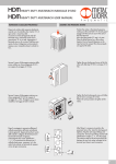
1
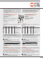
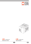
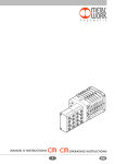
+ PROFIBUS DP
USER MANUAL
+ PROFIBUS DP
MANUALE D’USO
I
GB
Le valvole Heavy Duty Multimach - Profibus DP consentono il collegamento di isole
HDM ad una rete Profibus. Conformi alle specifiche Profibus DP DIN E 19245, offrono
funzioni di diagnostica e sono disponibili nella configurazione fino a 16 out.
1. CARATTERISTICHE
1.1 ALIMENTAZIONE
Per l’alimentazione elettrica si utilizza un connettore M8; l’alimentazione
di potenza è separata da quella del bus, per cui in caso di allarme si può
disinserire la potenza mentre la linea bus resta attiva. La mancanza di
alimentazione di potenza viene segnalata dall’accensione del led rosso EXT
FAULT. Il guasto viene segnalato al Master che deve provvedere ad una
adeguata gestione dell’allarme.
1.2 PROTEZIONI
Lo slave è protetto da inversione di polarità, da sovraccarichi mediante un
fusibile del tipo ripristinabile e i drivers di uscita integrano la protezione da
cortocircuito di ogni singola valvola. In caso di cortocircuito, segnalato
dall’accensione del led rosso EXT FAULT, solo la valvola guasta viene
disconnessa. Il guasto viene segnalato al Master che deve provvedere ad
una adeguata gestione dell’allarme. Dopo la rimozione della causa del
guasto, la segnalazione al master si resetta automaticamente, mentre
rimane attiva la segnalazione locale, EXT FAULT, per resettare l’allarme
si deve premere brevemente il pulsante di riarmo, oppure si deve togliere
alimentazione di potenza. Il fusibile e il pulsante di riarmo delle uscite si
trovano sotto al coperchio rettangolare. Sotto lo stesso coperchio si trovano
gli switch rotanti da utilizzare per l’indirizzamento e i dip switch per
l’inserimento delle resistenze di terminazione.
1.3 CONNESSIONI
I connettori Bus sono M12 con codifica di tipo B secondo la normativa
Profibus, per il collegamento si possono utilizzare anche cavi Profibus
precablati reperibili sul mercato, in modo da evitare i malfunzionamenti
dovuti a cablaggi difettosi. Per la connessione dell’alimentazione si deve
utilizzare un connettore M8 femmina 4 poli. Per la connessione del bus, in
alternativa ai cavi precablati, devono essere utilizzati dei connettori M12
metallici con il collegamento dello schermo del cavo al corpo del connettore.
Il collegamento dello schermo del connettore BUS IN a quello di BUS OUT,
è effettuato attraverso la filettatura M12 del coperchio metallico del modulo.
Lo slave deve essere collegato con la terra: per questo si può utilizzare uno
dei fori filettati del corpo metallico non utilizzato per il fissaggio dell’isola.
•
•
ATTENZIONE
La mancanza di collegamento a terra può causare, in caso di scariche
elettrostatiche, malfunzionamenti e danni irreversibili.
Per garantire il grado di protezione IP65 è necessario che gli scarichi
siano convogliati e che il connettore BUS OUT, in caso di inutilizzo, sia
tappanto.
2. ELEMENTI DI COLLEGAMENTO E SEGNALAZIONE
2
Heavy-Duty Multimach - Profibus DP valves can be used to link HDM islands to a
Profibus network. They comply with Profibus DP DIN E 19245 specifications, feature
diagnostic functions and are available with up to 16 outputs.
1. FEATURES
1.1 POWER SUPPLY
An M8 connector is used for the power supply, which is separate from that
of the bus, which means the power can be switched off if there is an alarm
while the bus line remains active. The EXT FAULT red light comes on when
the power supply is cut off. The fault is relayed to the Master, which must
provide adequate alarm management.
1.2 PROTECTIONS
The Slave is protected against polarity inversion and overloads by a
resettable fuse, and output drivers provide extra short-circuit protection for
each valve. Short-circuits are indicated by the EXT FAULT red light. In the
event of a short-circuit, only the faulty valve is disconnected. The fault is
relayed to the Master, which must proved adequate alarm management.
After the fault has been rectified, the Master signal resets automatically but
the local signal, EXT FAULT, remains active. To reset the alarm, press the
reset button briefly or switch off the power supply.
The fuse and reset button are located under the rectangular cover.
The rotary switches for addressing and the dip-switches for activating the
terminating resistances are located under the same cover.
1.3 CONNECTIONS
The Bus connectors are M12 with type B coding, in accordance with
Profibus standards. Pre-wired Profibus cables available from the trade can
also be used for connection in order to avoid malfunctions due to faulty
wiring. An M8 4-pin female connector must be used for connection to the
power mains. As an alternative to pre-wired cables, for the bus connection
you can use M12 metal connectors in which the cable shield is connected to
the body of the connector. The BUS IN and BUS OUT connector shields are
connected via the M12 threading of the metal cover of the module.
The Slave must be earthed. This can be done using one of the threaded
holes in the metal body not used for securing the island.
•
•
WARNING
Failure to earth the Slave properly may cause malfunctions and
serious damage in the event of electrostatic discharge.
In order to guarantee the protection degree IP65 it’s necessary that
the exhausts are conveyed and that - in case of no use - the
BUS OUT connector gets plugged.
2. CONNECTING AND SIGNALLING ELEMENTS
2.1 COLLEGAMENTI ELETTRICI: PIEDINATURA CONNETTORI
Connettore M8 per l’alimentazione del nodo e delle uscite
1 = +24VDC alimentazione nodo Profibus
2 = +24VDC alimentazione ausiliaria valvole
3 = GND
4 = GND
2.1 ELECTRICAL CONNECTIONS: CONNECTOR PIN CONFIGURATION
M8 connector for powering the node and outputs
1 = +24VDC Profibus node power supply
2 = +24VDC auxiliary valve power supply
3 = GND
4 = GND
Connettori per la connessione alla rete Profibus
BUS IN (connettore maschio)
BUS OUT (connettore femina)
1 = +5VDC *
1 = +5VDC *
2=A
2=A
3 = 0V *
3 = 0V *
4=B
4=B
5 = schermo
5 = schermo
Connectors for connection to the Profibus network
BUS IN (male connector)
BUS OUT (female connector)
1 = +5VDC *
1 = +5VDC *
2=A
2=A
3 = 0V *
3 = 0V *
4=B
4=B
5 = shield
5 = shield
ATTENZIONE
* NON COLLEGARE PIN 1 e PIN 3: da utilizzare solo l’alimentazione delle resistenze di terminazione esterne.
IMPORTANT
* DO NOT CONNECT PIN 1 and PIN 3: to be used only for feeding of the external terminating resistors.
• Per una corretta comunicazione, utilizzare cavi a norma Profibus con
lunghezza minima di 1 metro.
• Lo schermo deve essere collegato alla ghiera. Se ciò non fosse possibile,
lo si può collegare al pin 5. Entrambi questi metodi possono anche essere usati in combinazione.
2.2 COLLEGAMENTO E CONFIGURAZIONE DEL NODO
A Connessione al bus Profibus DP
B Connessione per l’alimentazione del nodo e per
l’alimentazione ausiliaria delle uscite
C Fusibile ripristinabile
D Pulsante di reset
E Selettore rotativo delle decine per l’indirizzamento del nodo
F Selettore rotativo delle unità per l’indirizzamento del nodo
G Interruttori per l’inserimento delle resistenze di
terminazione
H Leds di segnalazione
• For correct communication, use Profibus cables at least 1 metre long.
• The shield should be evenly distributed around the thread.
Should this not be possible, the shield can be connected to prin 5. Both of these methods can also be used in combination.
2.2 NODE CONNECTION AND CONFIGURATION
A Connection to the Profibus DP bus
B The node and the output power connection
C Resettable fuse
D Reset button
E Tenth selector for node addressing
F Unit selector for node addressing
G Terminating resistance switches
H Indicator lights
2.3 DIAGNOSTICA
La diagnostica di un modulo HDM AS-I, è definita dallo stato dei LEDs di
interfaccia:
2.3 DIAGNOSTICS
The diagnostics of an HDM-Profibus module is defined by the status of the
interface lights.
LED Verde LED Verde LED Rosso
Power ON BUS OK
BUS error
Green PowerGreen BUS Red BUS
ON light OK light error light
LED RossoSIGNIFICATO
EXT fault
ON (verde) ON (verde) OFF
OFF Il modulo funziona
correttamente.
OFF OFF
OFF
OFF
Il modulo non è alimentato
ON (verde) OFF
ON (rosso) OFF
Il modulo non comunica
con la rete
ON (verde) ON (verde) OFF
ON (rosso) Manca l’alimentazione
e ausiliaria o si è verificato
un guasto sulle uscite
3. INSTALLAZIONE E CONFIGURAZIONE DEL NODO
Red EXT MEANING
fault light
ON (green) ON (green) OFF
OFF The module is operating
correctly.
OFF OFF
OFF
OFF
The module is not powered on
ON (green) OFF
ON (red) OFF
The module is not communicating
with the network
ON (green) ON (green) OFF
ON (red) No auxiliary power supply
or output failure
3. NODE INSTALLATION AND CONFIGURATION
Gli elementi per la configurazione e il ripristino del corretto funzionamento,
si trovano sotto il coperchio di chiusura. Per accedervi svitare le due viti con
una chiave esagonale da 2.5 mm.
The elements required for the configuration and resumption of correct
operation are situated below the cover, which can be removed by
unscrewing the two screws using a 2.5 mm hexagonal wrench.
AVVERTENZE
• Disattivare la tensione prima di inserire o disinserire i connettori
(pericolo di danni funzionali).
• Collegare il modulo a terra, mediante un conduttore appropriato.
Eventualmente utilizzare per il collegamento uno dei fori di fissaggio libero. La mancanza di collegamento a terra può causare, in caso di
scariche elettrostatiche, malfunzionamenti e danni irreversibili.
• Utilizzare solamente unità di valvole completamente assemblate.
• Per l’alimentazione utilizzare esclusivamente alimentatori a norma
IEC 742/ EN60742/VDE0551 con resistenza di isolamento minima di 4kV (PELV).
WARNING
• Power off the system before inserting or removing the connectors
(risk of functional damage).
• Earth the module using the correct wire. Use one of the free holes, if
necessary. Failure to earth the system properly may cause malfunctions and serious damage in the event of electrostatic
discharge.
• Only use fully assembled valve units.
• Only use power supply units to IEC 742/ EN60742/VDE0551
standards with a minimum insulation resistance of 4kV (PELV).
3.1 INDIRIZZAMENTO
Prima di collegare uno Slave al sistema bus, si consiglia di assegnargli un
indirizzo non ancora occupato. L’indirizzo del nodo si configura impostando
sui selettori rotativi delle decine (E) e delle unità (F), il numero desiderato.
3.1 ADDRESSING
Before connecting a Slave to the bus system, it is advisable to assign it an
address. The node address is configured by entering the desired number on
the selectors for tenths (E) and units (F).
3.2 INSERIMENTO DELLE RESISTENZE DI TERMINAZIONE
L’ultimo nodo di ogni ramo della rete Profibus, deve essere terminato con le
apposite resistenze. Questo per evitare errori di riflessione durante la
comunicazione Master - Slave che possono generare malfunzionamenti.
L’inserimento si ottiene impostando su ON i due interruttori (G).
3.2 ACTIVATION OF TERMINATING RESISTANCES
The last node of each branch of the Profibus network must be terminated
with the required resistances. This is to avoid reflection errors during
Master-Slave communication, which can generate malfunctions. They can
be activated by pressing ON on the two switches (G).
ATTENZIONE
Per una migliore immunità ai disturbi, mantenere la velocità di comunicazione
più bassa possibile, compatibilmente con l’applicazione specifica.
IMPORTANT
To improve immunity to disturbance, keep the communication speed as slow as
possible, depending on the specific application.
3
3.3 RESET DEGLI ALLARMI
In caso di cortocircuito o sovraccarico di un uscita, interviene il circuito di
protezione che scollega l’uscita difettosa, mentre tutte le altre rimangono
attive. Contemporaneamente viene attivata sia la segnalazione locale con
l’accensione del Led EXT FAULT, che la segnalazione
al Master.
La segnalazione al Master si resetta automaticamente
alla rimozione del guasto.
Per resettare la segnalazione locale EXT FAULT, è
necessario premere il pulsante di reset (D) posizionato
sotto il coperchio, oppure togliere l’alimentazione di
potenza (24Vdc valvole). In caso di interruzione
dell’alimentazione ausiliaria delle uscite, viene
attivata sia la segnalazione locale con l’accensione del
Led EXT FAULT, che la segnalazione di errore al Master.
La segnalazione si resetta automaticamente al ripristino
dell’alimentazione.
In caso di superamento della corrente massima
simultanea, interviene il fusibile resettabile (C), che
sconnette l’alimentazione del nodo.
Per ripristinare il corretto funzionamento, scollegare il
cavo di alimentazione, rimuovere la causa del guasto e
ricollegare il cavo di alimentazione.
3.3 ALLARM RESET
In the event of an output short-circuit or overload, the safety circuit
disconnects the output but all the others remained active. At the same time,
the local signal is activated, and the EXT FAULT light comes on, as well as
the Master signal.
The Master signal resets automatically when the fault has
been rectified.
To reset the EXT FAULT local signal, press the reset
button (D) under the cover, or power off (24Vdc valves).
If the auxiliary power supply to the outputs is
interrupted, the local signal is activated, and the EXT FAULT
light comes on, as well as the Master error
signal. The signal resets automatically when the power
comes back on.
If the maximum simultaneous current is exceeded, the resettable fuse (C) cuts off power to the node.
If this happens, disconnect the power cable, remove the
cause of the fault and then reconnect it.
4. ASSEGNAZIONE DEI BIT DI DATI AGLI OUTPUT NEL SINGOLO NODO
4. ASSIGNING DATA BITS TO THE OUTPUTS FOR EACH NODE
bit 0
Out 1
bit 0
Out 1
bit 1
Out 2
bit 2
Out 3
bit 3
Out 4
...
...
bit 15
Out 16
bit 2
Out 3
bit 3
Out 4
...
...
bit 15
Out 16
4.1 INDIRIZZI DI USCITA DEI SOLENOIDI PER SINGOLO NODO, ESEMPIO:
4.1 SOLENOID OUTPUT ADDRESSES FOR EACH NODE, EXAMPLE:
Valvola Valvola
Valvola
Valvola Valvola
Valvola
Bistabile Monostabile Monostabile Bistabile Bistabile Monostabile
Out 3
Out 4
Out 5 ...
Out 16
Out 1
Out 2
Out 6 ...
La mappatura degli indirizzi è in funzione della configurazione del Master.
Bistable Monostable Monostable Bistable Bistable
valve
valve
valve
valve
valve
Out 3
Out 4
Out 5 ...
Out 1
Out 2
Out 6 ...
Address mapping depends on Master configuration.
5. DATI TECNICI
DESCRIZIONE
Impostazioni di fabbrica: indirizzo
Alimentazione
Protezione
Assorbimento di corrente max
(tutte le valvole ON)
Indirizzameto
N° max dell’indirizzo impostabile
Diagnostica di difetto periferico
Difetti segnalati
For general features, refer to the pneumatics section.
DESCRIPTION
MODULO PROFIBUS DP PER VALVOLE HDM
Factory setting: address
Power supply
3
24VDC +/- 10%
Slave protetto da sovraccarico e da inversione di
polarità
Uscite protette da sovraccarichi e cortocircuiti
~ 500 mA
Protection
Max input current
(all valves ON)
Addressing
Max. settable address numbers
Peripheral defect diagnostics
Defects signalled
Tramite selettori rotativi
99
Segnalazione locale tramite LED e segnalazione al Master
Cortocircuito o sovraccarico dell’uscita
Mancanza delll’alimentazione ausiliaria
Stato del modulo in caso di difetto
Comunicazione Profibus attiva
periferico
Il bit “Difetto Periferico” è attivo e accessibile alla
stazione master
Valore del bit di dato
0 = non attivo
1 = attivo
Stato delle uscite in assenza di
Inattive
comunicazione
www.metalwork.eu
Monostable
valve
Out 16
5. TECHNICAL DATA
Per le caratteristiche generali, vedi la descrizione della parte pneumatica.
4
bit 1
Out 2
Module status in the event of a
peripheral defect
Data bit value
Output status in the absence of
communication
DP PROFIBUS MODULE FOR HDM VALVES
3
24VDC +/- 10%
Slave protected by overload and polarity reversal
Outputs protected from overloads and short-circuits
~ 500 mA
Via rotary selectors
99
LED local signal and Master signal
Output short-circuit or overload
No auxiliary power
Profibus communication active
The “Peripheral Defect” bit is active and accessible at
the Master station
0 = not active
1 = active
Inactive
ELZZZZ129 - IM04_05/2012