1
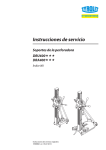
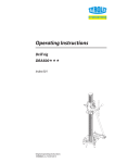
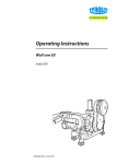
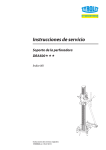
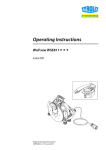
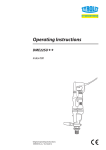
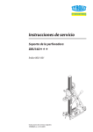
Operating Instructions Drill rigs DRU400 DRA400 Index 001 Original operating instructions 10988838 en / 03.07.2013 Congratulations! With a Hydrostress unit from TYROLIT you have chosen a tried and tested piece of equipment designed and built to the highest technical standards. Only genuine TYROLIT Hydrostress replacement parts can guarantee quality and interchangeability. If maintenance work is neglected or carried out inexpertly we will be unable to honour our warranty obligations. Any repair work must be carried out by trained personnel only. Our after-sales service is available to help ensure that your TYROLIT Hydrostress units remain in perfect working order. We hope that working with your TYROLIT unit will be a satisfying and fault-free experience. TYROLIT Hydrostress Copyright © TYROLIT Hydrostress TYROLIT Hydrostress AG Witzbergstrasse 18 CH-8330 Pfäffikon Switzerland Tel. 0041 (1) 952 18 18 Fax 0041 (1) 952 18 00 Page 2 TYROLIT Hydrostress AG 1 Safety These instructions are just one part of the documentation which is supplied together with the drill rig. These instructions go together with the "Core Drill Safety Manual / System Description" to form a complete set of documentation. DANGER Failure to comply with the safety instructions in the "Core Drills Safety Manual / System Description" may result in serious injury or even death. XX Please ensure that the "Core Drills Safety Manual / System Description" has been read and understood in full. DANGER Death or serious injury can be caused by a sudden start-up of the machine. XX Before switching on the system, ensure that no other person is present in the danger areas. XX Switch the system off before connecting or disconnecting cables. XX Switch the system off when you leave and secure it so that it cannot be switched back on again. Death or serious injury as a result of the drill bit continuing to run after an accident. XX Ensure that the ON / OFF button can be reached quickly. Electric shock from live cables and connectors. XX Switch the drill motor off before connecting or disconnecting cables. Risk of fire due to incorrect mains voltage. XX Make sure that the mains voltage and mains frequency match the mains settings of the drill motor. Page 3 TYROLIT Hydrostress AG 2 Description 2.1 Core drilling system The DRU400 and DRA400 drill rigs are part of core drill systems comprising the appropriate TYROLIT Hydrostress components. Example: DRU400 Core drilling system 1 2 3 4 Page 4 Vacuum pump Vacuum hose Vacuum seal Vacuum cap 5 6 7 Drill bit Drill motor Drill rig TYROLIT Hydrostress AG 2.2 Main components of the DRU400 Main components of the DRU400 1 2 3 4 5 6 2.3 Cap Column Gear support Level Centre indicator Vacuum foot 7 8 9 10 11 Vacuum valve Support rod Locking device for support Hand crank Grip Main components of the DRA400 Main components of the DRA400 1 2 3 4 5 Cap Column Gear support Level Dowel foot 6 7 8 9 Support rod Locking device for support Hand crank Grip Page 5 TYROLIT Hydrostress AG 3 Assembly 3.1 Locking the support XX 3.2 Drill motor interface 99 Lock the support before securing the drill motor. (see 3.1 Locking the support) 3.2.1 Mounting the drill motor XX Page 6 TYROLIT Hydrostress AG 3.3 3.3.1 Surface interface Dowel anchoring The DRA400 and DRU400 drill rigs can be securely attached to the surface with dowel anchoring. Information on safe dowel anchoring can be found in the "Core Drills Safety Manual / System Description". 3.3.2 Vacuum fixing The DRU400 drill rig can be securely attached to the surface with the appropriate TYROLIT Hydrostress components. Information on safe vacuum anchoring can be found in the "Core Drills Safety Manual / System Description". Page 7 TYROLIT Hydrostress AG 4 Settings 4.1 Angled position XX 4.2 Brake XX Page 8 TYROLIT Hydrostress AG 4.3 Adjusting the rollers XX Page 9 TYROLIT Hydrostress AG 5 Servicing and maintenance Yearly X X X X X X XX Clean teeth of guide column Support After damage X XX Lubricate threads of adjustable feet XX Tighten loose screws and nuts Weekly X XX Wash down with water After faults Drill rigs At end of work Before starting up (every time) Maintenance and servicing table X XX Tighten loose screws and nuts X X XX Check roller guide and adjust if necessary (see roller adjustment 4.2) X X X XX Replace roller guide Service Page 10 XX To be performed by TYROLIT Hydrostress AG or an authorised workshop. X First service after 100 operating hours Further services after every further 200 operating hours TYROLIT Hydrostress AG 6 Faults Malfunctions Malfunction Possible cause Solution Diamond drill bit jams Diamond drill bit off centre due to inadequate anchoring of guide rail or drill rig foot XX Loosen and extract diamond drill bit. Break up drilling core and correct drill rig anchoring. Diamond drill bit drifts due to excessive play in the roller guides XX Loosen drill rig and readjust roller guides Drill segments are worn (No free cutting) XX Replace drill bit Diamond drill bit poorly guided in the drill hole XX Adjust roller guides Defective drill motor bearings XX Replace drill motor XX Contact TYROLIT Hydrostress AG aftersales. Feed jams along the whole length of the guide rail Locking device on the roller guides is too tight. XX Adjust roller guide clamping Feed jams at one point on the guide rail Guide rail is distorted or damaged XX Contact TYROLIT Hydrostress AG aftersales Difficulty in centring drill bit Diamond drill bit off centre due to poor anchoring of the drill rig XX Correct drill rig anchoring Diamond drill bit drifts due to excessive play in the roller guides XX Adjust roller guides Poor concentricity of drill bit XX Replace drill bit XX Use TYROLIT diamond tool Difficult or impossible to twist the foot adjustment screw Thread not lubricated XX Lubricate thread Feet distorted XX Contact TYROLIT Hydrostress AG aftersales Difficult or impossible to incline the drill rig Guide rail distorted or damaged XX Contact TYROLIT Hydrostress AG aftersales. Vacuum cannot be generated Defective vacuum seal on vacuum foot XX Replace vacuum seal Defective vacuum valve on vacuum foot XX Replace vacuum valve Defective vacuum pump or hose XX Replace vacuum pump or hose Surface not suitable for vacuum anchoring XX Choose another type of anchoring Major wear on the drill bit tube Page 11 TYROLIT Hydrostress AG 7 Technical data Dimensions Dimensions DRU400 DRA400 Length L 507 mm 305 mm Width B 300 mm 205 mm Height H 1,063 mm 1,055 mm DRU400 DRA400 18 kg 19 kg Weights Weight (without hand crank) Page 12 TYROLIT Hydrostress AG Drill bits DRU400 DRA400 Ø 50 – Ø 250 mm Ø 50 – Ø 250 mm Max. drill diameter with 180 mm distance plate Ø 400 mm Ø 250 mm (vacuum) Ø 400 mm Drill diameter range with vacuum anchoring Ø 50 – Ø 250 mm – Max. drill diameter with water collection ring Ø 250 mm – 737 mm 746 mm DRU400 DRA400 Aluminium dowel vacuum foot Steel dowel foot Drill diameter range with dowel anchoring Max. drill bit length Design Foot Feed gears Two-speed feed gearbox i = 1:1 and i = 1:3.5 Feed Angular adjustment Centre indicator Adjustable feet Drill motor mount Support guide by hand crank 90°-45° with angle display Indicator retractable No indicator M12 bolt ModulDrill quick change clamping system Adjustable interchangeable roller guide Page 13 TYROLIT Hydrostress AG 8 EC Declaration of Conformity Description Drill rigs Type designation DRU400 DRA400 Year of construction 2009 We declare under our sole responsibility that this product complies with the following directives and standards: Directive applied Machinery Directives 2006/42/EC Applied standards EN 12100-1 EN 12100-2 Safety of machinery – Basic concepts, general design principles. EN 12348 Core drilling machines on stands - Safety EN 14121-1 Safety of machines - Risk assessment, Part 1: Principles In the system with drill motors: EC Low Voltage Directive Vibration Regulation Noise Protection Regulation Page 14 2006/95/EC 2002/44/EC 2000/14/EC