1
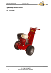
Operating Instructions Wall saw WSE811 Index 000 Original operating instructions 10995043 en / 05. June 2015 Congratulations! You have decided to purchase a tried-and-tested TYROLIT Hydrostress unit and have thus acquired a highly sophisticated and reliable state-of-the-art device. Only genuine TYROLIT Hydrostress replacement parts can guarantee quality and interchangeability. If maintenance work is neglected or carried out inexpertly, we will be unable to honour our warranty obligations. All repairs must be carried out by trained personnel only. Our after-sales service is available to help ensure that your TYROLIT Hydrostress units remain in perfect working order. We hope that working with your TYROLIT unit will be a satisfying and fault-free experience. TYROLIT Hydrostress Copyright © TYROLIT Hydrostress TYROLIT Hydrostress AG Witzbergstrasse 18 CH-8330 Pfäffikon Switzerland Tel. 0041 (0) 44 952 18 18 Fax 0041 (0) 44 952 18 00 Page 2 Wall saw WSE811 TYROLIT Hydrostress AG Table of contents Page 1.Safety . . . . . . . . . . . . . . . . . . . . . . . . . . . . . . . . . . . . . . . . . . . . . . . . . . . . . . . . . . . . . . . . . . . . . . . . . . . 5 1.1 Generally applicable safety instructions. . . . . . . . . . . . . . . . . . . . . . . . . . . . . . . . . . . . . 5 1.2 Signs on the equipment. . . . . . . . . . . . . . . . . . . . . . . . . . . . . . . . . . . . . . . . . . . . . . . . . . . . 6 1.3 Action in an emergency . . . . . . . . . . . . . . . . . . . . . . . . . . . . . . . . . . . . . . . . . . . . . . . . . . . . 6 2.Description . . . . . . . . . . . . . . . . . . . . . . . . . . . . . . . . . . . . . . . . . . . . . . . . . . . . . . . . . . . . . . . . . . . . . 7 2.1 Wall saw system. . . . . . . . . . . . . . . . . . . . . . . . . . . . . . . . . . . . . . . . . . . . . . . . . . . . . . . . . . . . 7 2.2 Intended use. . . . . . . . . . . . . . . . . . . . . . . . . . . . . . . . . . . . . . . . . . . . . . . . . . . . . . . . . . . . . . . 7 2.3 Wall saw system components. . . . . . . . . . . . . . . . . . . . . . . . . . . . . . . . . . . . . . . . . . . . . . . 7 2.4 Wall saw head with integrated control unit. . . . . . . . . . . . . . . . . . . . . . . . . . . . . . . . . . 8 2.5 Remote controller. . . . . . . . . . . . . . . . . . . . . . . . . . . . . . . . . . . . . . . . . . . . . . . . . . . . . . . . . . 3.Assembly/disassembly. . . . . . . . . . . . . . . . . . . . . . . . . . . . . . . . . . . . . . . . . . . . . . . . . . . . . . . . . . Wall saw WSE811 9 12 3.1 Placing the wall saw on the guide rail . . . . . . . . . . . . . . . . . . . . . . . . . . . . . . . . . . . . . . . 12 3.2 Adjusting the guide rollers. . . . . . . . . . . . . . . . . . . . . . . . . . . . . . . . . . . . . . . . . . . . . . . . . . 13 3.3 Mounting the saw blade. . . . . . . . . . . . . . . . . . . . . . . . . . . . . . . . . . . . . . . . . . . . . . . . . . . . 14 3.4 Mounting the blade guard. . . . . . . . . . . . . . . . . . . . . . . . . . . . . . . . . . . . . . . . . . . . . . . . . . 17 3.5 Mounting the blade guard. . . . . . . . . . . . . . . . . . . . . . . . . . . . . . . . . . . . . . . . . . . . . . . . . . 17 3.6 Establishing the mains connection and water supply. . . . . . . . . . . . . . . . . . . . . . . . 18 4.Operation . . . . . . . . . . . . . . . . . . . . . . . . . . . . . . . . . . . . . . . . . . . . . . . . . . . . . . . . . . . . . . . . . . . . . . . 21 4.1 Overview of controls . . . . . . . . . . . . . . . . . . . . . . . . . . . . . . . . . . . . . . . . . . . . . . . . . . . . . . . 21 4.2 Starting the wall saw . . . . . . . . . . . . . . . . . . . . . . . . . . . . . . . . . . . . . . . . . . . . . . . . . . . . . . . 22 4.3 Frequency change of the remote controller . . . . . . . . . . . . . . . . . . . . . . . . . . . . . . . . . 23 4.4 Selecting the tool station. . . . . . . . . . . . . . . . . . . . . . . . . . . . . . . . . . . . . . . . . . . . . . . . . . . 24 4.5 Adjusting the feed. . . . . . . . . . . . . . . . . . . . . . . . . . . . . . . . . . . . . . . . . . . . . . . . . . . . . . . . . . 24 4.6 Manually adjusting the feed speed. . . . . . . . . . . . . . . . . . . . . . . . . . . . . . . . . . . . . . . . . . 25 4.7 Locking the feed . . . . . . . . . . . . . . . . . . . . . . . . . . . . . . . . . . . . . . . . . . . . . . . . . . . . . . . . . . . 25 4.8 Switching off the wall saw . . . . . . . . . . . . . . . . . . . . . . . . . . . . . . . . . . . . . . . . . . . . . . . . . . 26 4.9 Blowing out water. . . . . . . . . . . . . . . . . . . . . . . . . . . . . . . . . . . . . . . . . . . . . . . . . . . . . . . . . . 26 4.10 Deactivating the EMERGENCY STOP. . . . . . . . . . . . . . . . . . . . . . . . . . . . . . . . . . . . . . . . . 27 4.11 After finishing the work. . . . . . . . . . . . . . . . . . . . . . . . . . . . . . . . . . . . . . . . . . . . . . . . . . . . . 27 4.12 Reacting to displays. . . . . . . . . . . . . . . . . . . . . . . . . . . . . . . . . . . . . . . . . . . . . . . . . . . . . . . . 28 Page 3 TYROLIT Hydrostress AG 5. Servicing and maintenance. . . . . . . . . . . . . . . . . . . . . . . . . . . . . . . . . . . . . . . . . . . . . . . . . . . . . 31 5.1Cleaning. . . . . . . . . . . . . . . . . . . . . . . . . . . . . . . . . . . . . . . . . . . . . . . . . . . . . . . . . . . . . . . . . . . 31 5.2 Blowing out water. . . . . . . . . . . . . . . . . . . . . . . . . . . . . . . . . . . . . . . . . . . . . . . . . . . . . . . . . . 32 5.3 Replacing the guide rollers . . . . . . . . . . . . . . . . . . . . . . . . . . . . . . . . . . . . . . . . . . . . . . . . . 5.4 Lubricating the lock unit . . . . . . . . . . . . . . . . . . . . . . . . . . . . . . . . . . . . . . . . . . . . . . . . . . . 33 5.5 Cleaning the water filter. . . . . . . . . . . . . . . . . . . . . . . . . . . . . . . . . . . . . . . . . . . . . . . . . . . . 33 5.6 Changing the gear oil. . . . . . . . . . . . . . . . . . . . . . . . . . . . . . . . . . . . . . . . . . . . . . . . . . . . . . . 34 5.7 Taking waste for recycling . . . . . . . . . . . . . . . . . . . . . . . . . . . . . . . . . . . . . . . . . . . . . . . . . . 34 32 6.Malfunctions . . . . . . . . . . . . . . . . . . . . . . . . . . . . . . . . . . . . . . . . . . . . . . . . . . . . . . . . . . . . . . . . . . . . 35 7. Technical data . . . . . . . . . . . . . . . . . . . . . . . . . . . . . . . . . . . . . . . . . . . . . . . . . . . . . . . . . . . . . . . . . . 37 7.1Dimensions . . . . . . . . . . . . . . . . . . . . . . . . . . . . . . . . . . . . . . . . . . . . . . . . . . . . . . . . . . . . . . . . 37 7.2Weight. . . . . . . . . . . . . . . . . . . . . . . . . . . . . . . . . . . . . . . . . . . . . . . . . . . . . . . . . . . . . . . . . . . . . 38 7.3Design. . . . . . . . . . . . . . . . . . . . . . . . . . . . . . . . . . . . . . . . . . . . . . . . . . . . . . . . . . . . . . . . . . . . . 38 Page 4 7.4 Saw blade drive motor. . . . . . . . . . . . . . . . . . . . . . . . . . . . . . . . . . . . . . . . . . . . . . . . . . . . . . 38 7.5 Feed motor, travel. . . . . . . . . . . . . . . . . . . . . . . . . . . . . . . . . . . . . . . . . . . . . . . . . . . . . . . . . . 38 7.6 Feed motor, swivel. . . . . . . . . . . . . . . . . . . . . . . . . . . . . . . . . . . . . . . . . . . . . . . . . . . . . . . . . . 39 7.7 Noise level . . . . . . . . . . . . . . . . . . . . . . . . . . . . . . . . . . . . . . . . . . . . . . . . . . . . . . . . . . . . . . . . . 39 7.8 Saw blades. . . . . . . . . . . . . . . . . . . . . . . . . . . . . . . . . . . . . . . . . . . . . . . . . . . . . . . . . . . . . . . . . 39 7.9 Lubricants and fluids . . . . . . . . . . . . . . . . . . . . . . . . . . . . . . . . . . . . . . . . . . . . . . . . . . . . . . . 40 7.10Water. . . . . . . . . . . . . . . . . . . . . . . . . . . . . . . . . . . . . . . . . . . . . . . . . . . . . . . . . . . . . . . . . . . . . . 40 7.11 Recommended ambient temperature. . . . . . . . . . . . . . . . . . . . . . . . . . . . . . . . . . . . . . . 40 7.12 Electrical data. . . . . . . . . . . . . . . . . . . . . . . . . . . . . . . . . . . . . . . . . . . . . . . . . . . . . . . . . . . . . . 40 7.13 Remote controller. . . . . . . . . . . . . . . . . . . . . . . . . . . . . . . . . . . . . . . . . . . . . . . . . . . . . . . . . . 41 7.14 Name plate. . . . . . . . . . . . . . . . . . . . . . . . . . . . . . . . . . . . . . . . . . . . . . . . . . . . . . . . . . . . . . . . . 41 8. EC Declaration of Conformity . . . . . . . . . . . . . . . . . . . . . . . . . . . . . . . . . . . . . . . . . . . . . . . . . . . 42 Wall saw WSE811 TYROLIT Hydrostress AG 1 Safety 1.1 Generally safety instructions These instructions are just one part of the documentation which is supplied together with the wall saw. These instructions go together with the "Safety Manual/System Description for Wall Saws" to form a complete set of documentation. DANGER Failure to comply with the safety instructions in the "Safety Manual/System Handbook" and the operating instructions may result in serious injury or even death. XX Please ensure that the "Safety Manual/System Description for Wall Saws" and the operating instructions have been read and understood in full. DANGER Laceration from the saw blade. XX Always wear protective gloves when working on the wall saw, particularly when working on the saw blade. XX Always use the blade guard when operating the wall saw. DANGER Serious injury or material damage as a result of uncontrolled movements of the wall saw. XX Never connect or disconnect cables when the wall saw is running. DANGER Death or serious injury can be caused by sudden start-up of the machine. XX Before switching on the system, ensure that no other persons are present in the danger areas. XX On leaving the system, switch it off and ensure that it cannot be switched on again. DANGER Death or serious injury as a result of the sawing machine continuing to run after an accident. XX Ensure that the EMERGENCY STOP button can be reached quickly. DANGER Electric shock from live cables and connectors. XX Switch off the wall saw WSE811 before connecting or disconnecting cables. XX Ensure that the power supply is earthed and fitted with a residual current circuit breaker (FI Type B) with a maximum residual current of 30 mA. DANGER Risk of fire due to incorrect mains voltage. XX Make sure that the mains voltage and mains frequency correspond with the mains settings of wall saw WSE811. Wall saw WSE811 Page 5 TYROLIT Hydrostress AG 1.2 Signs on the machine Safety sign 1 Wear safety shoes 2 Wear gloves 3 4 Wear a breathing mask Wear a helmet, goggles and hearing protection 5 6 Read the instructions Before working on the equipment unplug mains Name plate 1.3 Behaviour in an emergency XX Press the EMERGENCY STOP button on the remote controller. If the EMERGENCY STOP is activated on the radio remote controller, the LED warning light flashes rapidly. In an emergency, the sawing machine can be also switched off using the main switch on the saw head of the WSE811. EMERGENCY STOP Page 6 Wall saw WSE811 TYROLIT Hydrostress AG 2 Description 2.1 Wall saw system The design and function of the wall saw systems are described in the “Safety Manual/System Description for Wall Saws”. 2.2 Intended use Transportable wall saw for use on construction sites, for cutting (reinforced) concrete, stone and masonry. Only for industrial use. Not suitable for use in potentially explosive atmospheres. 2.3 Wall saw system components Wall saw system 1 2 3 4 Wall saw WSE811 Radio remote controller Mains cable with connector Rail Rotating rail support 5 6 7 8 Wall saw head with integrated control unit Undercarriage Diamond wire saw Blade guard Page 7 TYROLIT Hydrostress AG 2.4 Wall saw head with integrated control unit 2.4.1 Wall saw head components Components 1 Mains cable with connector 2 Undercarriage 3 Casing 4 5 6 7 8 9 Page 8 Protective hood Guide roller Diamond saw blade flange Protective holder Grip Rotating chassis 10 Blade guard uptake 11 Water connections 12 Connector to the remote controller cable 13 Roller locking handle 14 Main ON/OFF switch 15 Hour counter Wall saw WSE811 TYROLIT Hydrostress AG 2.5 Remote controller The remote controller can be used to control all functions of the wall saw WSE811★★★. The saw blade speed is automatically adjusted using the diameter selector switch on the remote controller. The remote controller can be used as a radio remote controller with a rechargeable battery or an ordinary battery. Additionally, the remote controller can be operated using a cable. Radio remote controller The transmitter and receiver are a pair of matched units. They cannot be used with other devices. The number on the back of the remote controller must match the serial number on the machine name plate. Serial number 2.5.1 Operating modes Rechargeable battery operation: The interchangeable rechargeable battery is inserted in the base of the casing of the remote controller. The operating period with a fully charged battery is approximately 12 hours. The reception distance is approx. 25 m. Ordinary battery operation: The battery holder is included in the scope of supply and allows operation with three 1.5-V AA batteries. The reception distance is approx. 25 m. Cable operation: The cable insert is included in the scope of supply and allows connection of the remote controller to the control unit WSE811. The cable length is 10 m. Cable operation makes it possible to work in areas where radio operation is not allowed (e.g. hospitals). When working with the cable connection, all control signals are transmitted via the electric cable. The rechargeable/ordinary battery holders must not be inserted in the base of the casing during cable operation. Wall saw WSE811 Page 9 TYROLIT Hydrostress AG 2.5.2 Main components of remote controller Main components of remote controller 1 2 3 4 5 6 7 8 9 Page 10 EMERGENCY STOP On/Off, main motor Diameter selector switch Water On/Off Locking button (traverse feed) Cable connection Reset button Feed motor potentiometer Indicator lights 10 11 12 13 14 15 Warning light (radio & battery) Feed joystick Start switch Casing Remote controller pulse button Hip belt Wall saw WSE811 TYROLIT Hydrostress AG 2.5.3 Accessories for remote controller The battery charger is exclusively for recharging the interchangeable rechargeable batteries. The battery holder and the cable connection must not be inserted. Accessories 1 2x interchangeable rechargeable batteries 2 Rechargeable battery charger Wall saw WSE811 No. 10984306 No. 10984305 Rechargeable battery charger with 10–30 VDC connection No.10984840 3 Remote controller cable 4 Battery holder 5 Key No. 10991362 No. 10984307 No. 10984309 Page 11 TYROLIT Hydrostress AG 3 Assembly/disassembly 3.1 Placing the wall saw on the guide rail Assembly of wall saw If the swivelling handle fails to engage or the wall saw sits too loosely on the guide rail: adjust the guide rollers. Page 12 Wall saw WSE811 TYROLIT Hydrostress AG 3.2 Adjusting the guide rollers 99 Tool Fork wrench Size 22 TYROLIT no. 10995086 Allen key Size 8 Allen key Size 5 (grips must be removed first) Adjusting the guide rollers The guide rollers are set correctly when they align in the roller groove and it is possible to turn them by hand. In order for the machine to travel parallel to the rail, both guide rollers must be adjusted identically. Wall saw WSE811 Page 13 TYROLIT Hydrostress AG 3.3 Assembling the saw blade DANGER Death or serious injury can be caused by an escaping saw blade. XX Only use original screws and bolts from TYROLIT Hydrostress AG. DANGER Serious injury can be caused by sudden start-up of the saw blade. XX Switch off the wall saw before working on the saw blade. XX Isolate the wall saw from the mains supply. The direction of rotation of the saw blade must match the direction of rotation of the machine. Correct alignment: Countersinking of the fixing holes against the blade cover. 3.3.1 Saw blade fixing for normal cutting Saw blade diameter Ø650 mm/Ø750 mm 99 Tool Fork wrench Size 19 Allen key Size 5 Saw blade fixing for normal cutting Page 14 Wall saw WSE811 TYROLIT Hydrostress AG 3.3.2 Saw blade uptake Diamond saw blades can be mounted on the wall saw WSE811 using uptake drill holes with Ø60 mm and Ø25.4 mm. For diamond saw blades with uptake drill hole Ø25.4 mm, the support spindle of the blade flat flange needs be rotated by 180°. 99 Tool Fork wrench Size 19 Allen key Size 5 Allen key Size 2.5 Saw blade uptake Disassembly help Two screws can be used as a disassembly help for the support spindle. 99 Tool Allen key Size 2.5 Disassembly help Wall saw WSE811 Page 15 TYROLIT Hydrostress AG 3.3.3 Saw blade fixing for flush cutting Saw blade diameter Ø650 mm/Ø750 mm 99 Tool Allen key Size 5 Allen key Size 6 Set screw M12x12 Saw blade fixing for flush cutting If the distance from the saw blade to the wall is more than 10 mm in places, then, for controlled cooling water distribution, a set screw M12x12 mm (TYROLIT no. 10981971) must be screwed flush in the centre of the saw blade uptake. Page 16 Wall saw WSE811 TYROLIT Hydrostress AG 3.4 Assembling the blade guard XX Assemble the blade guard according to the instruction leaflet. 99 Tool Fork wrench Size 19 Assembling/disassembling the blade guard 3.5 Disassembling the blade guard Disassemble the blade guard in the reverse order to the installation/assembly process. Wall saw WSE811 Page 17 TYROLIT Hydrostress AG 3.6 3.6.1 Connecting the mains and water supply Mains 99 Connectors/plugs are clean 99 Cables are undamaged 99 The power supply is earthed and fitted with a residual current circuit breaker (FI type B; max. residual current 30 mA) 99 Sufficient cable cross-sections: up to 25 m long 4 x 2.5 mm2, more than 25 m long 4 x 4 mm2 3.6.2 Water Wet and dry cutting The wall saw WSE811 can be used for wet and dry cutting. Wet cutting Wet cutting Page 18 Wall saw WSE811 TYROLIT Hydrostress AG Dry cutting For dry cutting, the water is led away via a bypass. When dry cutting, continuous operation is not possible, because otherwise the gearbox will overheat. After using for a ¼ hour, a ½ hour break must be maintained for cooling: For dry cutting, special TYROLIT diamond saw blades must be used. Dry cutting Wall saw WSE811 Page 19 TYROLIT Hydrostress AG Cutting without the blade guard DANGER Danger from segments or concrete chips flying off from the cutting tool. XX Sawing without the blade guard is prohibited. If the blade guard is not mounted, the water emerges in an uncontrolled manner over the blade guard uptake. Cutting without the blade guard Page 20 Wall saw WSE811 TYROLIT Hydrostress AG 4 Operation 4.1 Overview of controls Controls on the remote controller 1 2 3 4 5 6 7 EMERGENCY STOP On/Off, main motor Diameter selector switch Water On/Off Locking button (traverse feed) Cable connection Reset button 8 9 10 11 Main motor potentiometer Feed joystick Start switch Remote controller pulse button Controls on the wall saw 1 2 3 4 Wall saw WSE811 Mains cable with connector Main ON/OFF switch Roller locking handle Connector to the remote controller cable 5 6 7 8 Water connection/water bypass Grip Blade guard uptake Diamond saw blade flange Page 21 TYROLIT Hydrostress AG 4.2 Starting the wall saw 99 The rail is firmly connected to the subsurface. 99 The wall saw head is correctly mounted on the rail. 99 The protective cup on the remote controller cable connector is locked securely. 99 The diamond tool is correctly secured using the blade flange. 99 The blade guard is correctly mounted. 99 The wall saw WSE811 is connected to the mains and the water supply. 99 The remote controller EMERGENCY STOP (1) has been deactivated. Starting the wall saw WSE811 XX Move the controls listed below on the remote controller to the 0 position. Feed potentiometer (8) Starter switch (14) Main motor On/Off (2) Water switch (4) XX Switch on the wall saw WSE811 using the main switch on the wall saw head. XX Switch on the radio remote controller using the starter switch (14). –– Warning light (12) lights up red at first –– An audible signal sounds simultaneously –– Indicators flash coloured –– Second audible signal sounds –– Warning light (12) flashes green XX Press the pulse button (15) on the remote controller briefly. –– The reset indicator (11) lights up blue. XX Press the reset button (7) on the remote controller. –– The ready indicator (9) flashes green. XX Press the pulse button (15) briefly. –– The ready indicator (9) lights up green. XX Open the water valve on the system supply line. XX Press the water On/Off switch (4) on the remote controller to 1. –– Water flows from the diamond tool. XX Using the diameter selector (3), choose the diamond tool diameter. XX Press the main motor On/Off switch (2) on the remote controller to position 1. –– The electric motor starts. XX The wall saw WSE811 has started and is ready for operation. Page 22 Wall saw WSE811 TYROLIT Hydrostress AG 4.3 Frequency change of the remote controller Frequency search The radio remote controller systems are equipped with a frequency generator for selecting a frequency. If the systems are malfunctioning or the radio connection is interrupted (external transmitter, range, rechargeable battery empty), the system immediately goes into the EMERGENCY STOP state. New frequency search: The next frequency is selected by switching the start switch on the remote controller off and then on again. The process of switching off and on is limited to four attempts (channels). If the system does not find a suitable frequency after four attempts, then a changeover to cable operation is necessary. Wall saw WSE811 Page 23 TYROLIT Hydrostress AG 4.4 Selecting the tool station After the wall saw WSE811 has been started correctly, you can select between the tool stations Ø650 mm or Ø750 mm. Selecting the tool station The tool stations must not be changed during operation. The tool stations are set with reference to the tool diameter for the optimum rotational speed and cutting performance. 4.5 Adjusting the feed The feed movements are selected with the joystick. Adjusting the feed During the cutting process, the feed speed is automatically supported by an assisted feed. Page 24 Wall saw WSE811 TYROLIT Hydrostress AG 4.6 Manually adjusting the feed speed 99 The wall saw WSE811 has been started XX Select the required feed speed via the potentiometer. Manually adjusting the feed speed 4.7 Locking the feed Locking the feed So that the joystick does not have to be held in position during the travel feed motion, the travel feed can be locked. Proceed as follows: XX Push the joystick in the desired travel direction and, at the same time, press the locking switch. XX When the joystick and the locking switch are released, the feed is locked. In order to release the feed lock, move the joystick slightly in any desired direction or press the locking button (traverse feed). Wall saw WSE811 Page 25 TYROLIT Hydrostress AG 4.8 Switching off the wall saw Switching off the wall saw Proceed as follows: XX Press the start switch (1) on the remote controller to the 0 position. XX Turn off the cooling water, switch (2) water 0/1. XX Switch off the wall saw WSE811 using the main switch (3). XX Switch off the WSE811 wall saw using the main switch on the wall saw head. Caution Frost can damage the wall saw WSE811! XX Blow out any water if there is a risk of frost (see chapter 4.9, Blowing out the water). Only stop the wall saw WSE811 using the EMERGENCY STOP function in an emergency. 4.9 Blowing out the water 99 The main switch is set to OFF XX Disconnect the mains plug. XX Disconnect all water lines. XX Connect the purge pump to the water nipple. XX Blow out water until all of the cooling water has been removed (see chapter 5.2). XX Remove the pump. Page 26 Wall saw WSE811 TYROLIT Hydrostress AG 4.10 Deactivating the EMERGENCY STOP If the EMERGENCY STOP is activated on the radio remote controller, the radio and battery light (5) flash quickly. Deactivating the EMERGENCY STOP The following controls must be moved to the 0 position: Potentiometer (3) Feed joy stick (6). Main motor On/Off (2). Turn the EMERGENCY STOP button (1) clockwise. Push the pulse button (7) to the ON position. 4.11 After finishing the work Proceed as follows: XX Disconnect the water hoses from the wall saw WSE811. XX Blow out the water from all the lines (see chapter 5.2). XX Turn the main switch on the wall saw WSE811 to the 0 position. XX Disconnect the mains plug. XX Clean the wall saw WSE811, the remote controller and the cables with a damp cloth. Cleaning using high pressure cleaning equipment is not permitted. Products containing cleaning agent can damage parts of the wall saw WSE811, the radio remote controller and the cables. Wall saw WSE811 Page 27 TYROLIT Hydrostress AG 4.12 Reacting to indicators Indicators Lights on the remote controller 1 Ready light 2 Service fault 3 Group alarm 4 5 Reset light Radio and battery Power and fault indicators on the remote controller Power and fault indicators on the remote controller Symbol Response Possible cause Action Flashes orange Rechargeable battery voltage too low XX Recharge rechargeable battery Flashes green rapidly No radio connection The EMERGENCY STOP has been activated XX Switch on the remote controller XX Defective receiver XX Connection not matched to receiver, see page 9 Flashes red • Group alarm on the remote controller • On operating the pulse switch on the remote controller, the main motor On/Off switch is in the On position XX Turn the potentiometer to the 0 position XX Put the main motor On/Off switch into the Off position Lights up yellow Service indicator: After the first 100 operating hours, then after every 200 operating hours. Carried out only by TYROLIT Hydrostress AG or an authorised representative Lights up green The motor is ready to start XX After 30 seconds of inactivity, the pulse button must be pressed again Flashes green The machine is in the standby position XX Press the pulse switch on remote controller Shows the current power range Ideally: At the second, orange-coloured diode (in iron the third, red diode). Page 28 Wall saw WSE811 TYROLIT Hydrostress AG Overview of flash code The flash code is used for fault detection and is displayed in red on the group alarm light on the remote controller. Flash code indicators Flash code for fault indicators Flash code Example 3x Fault Possible cause Action 2x Mains phase is missing • Fault during installation • Fuse defective • Check phases and fuses 3x DC motors are overheating • Absence of cooling • Allow machine to cool for 3 minutes • Avoid direct contact with sunlight Blade motor is overheating • Absence of cooling • No, too little or too hot cooling water • See Technical data, chapter 7.10 4x Wall saw WSE811 Short circuit fault • Contact TYROLIT Hydrostress AG after-sales service Short circuit detection • Earth fault • Contact TYROLIT Hydrostress AG after-sales service Main motor overcurrent • Main motor blocked • Overcurrent earth fault • Contact TYROLIT Hydrostress AG after-sales service Main motor earth fault • Electrical connection earth fault • Contact TYROLIT Hydrostress AG after-sales service Page 29 TYROLIT Hydrostress AG Flash codes for power and fault indicators Flash code Example 3x Fault Possible cause Action Overcurrent DC axis • Feed motor overloaded • Reduce feed DC motor short circuit • Blocked feed motor • Defective feed motor • Contact TYROLIT Hydrostress AG after-sales service The safety relay no longer switches properly • Hardware defect • Contact TYROLIT Hydrostress AG after-sales service The safety contact no longer functions properly. • Hardware defect • Contact TYROLIT Hydrostress AG after-sales service 7x Transformer fault • Motor outside of possible parameters • Contact TYROLIT Hydrostress AG after-sales service 8x Direct current link voltage too low • Incorrect mains voltage • Check the power supply See Technical data, chapter 7.12 Direct current link voltage too high • Mains overvoltage • The saw blade feeds back too much energy. • Check the power supply See Technical data, chapter 7.12 • Use only diamond saw blades with Ø650 mm and Ø750 mm Communication fault • Communication fault due to interference • Contact TYROLIT Hydrostress AG after-sales service 5x 6x 9x Page 30 Wall saw WSE811 TYROLIT Hydrostress AG 5 Servicing and maintenance Wall saw head Lock unit X X X X XX Check the condition and cleanliness of couplings. X X X X XX Retighten loose bolts, screws and nuts (refer to the tightening torque specifications) X X X XX Check cleanliness X X X X XX Clean latching recesses and guide grooves X X X X X X Guide rollers After faults Weekly X XX Lubricate (see chapter 5.4) After damage XX Check the condition and cleanliness of electric cables, plugs/connectors and switches. Annually On finishing work Electrical system Before starting up Maintenance and servicing table XX Check the bearing clearance for wear X X X X XX Clean X X X X X XX Replace (see chapter 5.3) Rotating chassis X XX Clean with water XX Check the saw blade uptake for wear X XX Change the gear oil (see chapter 5.5) Water economy Saw blade XX Check the water line for cleanliness and leak-tightness Service X X XX Clean with water X XX To be performed by TYROLIT Hydrostress AG or an authorised workshop 5.1 X X X X X Every 100 h XX Blow out water (see chapter 5.2) XX Check for wear X X X After 100/300/500/700 hours Cleaning Caution Cleaning using high pressure cleaning equipment is not permitted. Cleaning using high pressure cleaning equipment can damage the wall saw WSE811. Products containing cleaning agent can damage parts of the wall saw WSE811, the remote controller and the cables. Wall saw WSE811 Page 31 TYROLIT Hydrostress AG 5.2 Blowing out the water Blowing out the water The blade guard must be fitted, so that the water can be properly blown out of the lines. Use the TYROLIT purge pump, no.10982667. 5.3 Replacing the guide rollers Replacing the guide rollers XX Defective guide rollers should be replaced with the replacement set. Guide roller No.10993972 Eccentric roller No.10993974 Page 32 Wall saw WSE811 TYROLIT Hydrostress AG 5.4 Lubricating the lock unit Lubricating the lock unit Lubricating grease 1 Treat joints and lock unit with lubricant TYROLIT no. 975061 (spray). 2 Lubricate using a grease gun (EP Grease 2) 5.5 Cleaning the water filter 99 Tool Fork wrench Size 18 Cleaning the water filter Clean and disassemble the water filter Clean the water filter with warm water. Wall saw WSE811 Page 33 TYROLIT Hydrostress AG 5.6 Changing the gear oil The use of unsuitable oil can damage the wall saw. XX Use only TYROLIT Hydrostress AG oil containers (no. 10995817, 0.4 dl). 99 Tool Allen key Size 5 Oil container 0.4 dl (TYROLIT no.10995817) Change gear oil Allow gear oil to drain. To ensure all the gear oil can drain out, let the hub rotate for about a ½ hour. 5.7 Recycling waste TYROLIT Hydrostress power tools are manufactured using a high proportion of recyclable materials. A prerequisite for recycling is proper material separation. In many countries, TYROLIT is already prepared for taking back your used equipment for recycling. Contact TYROLIT customer service or your sales adviser. Page 34 Wall saw WSE811 TYROLIT Hydrostress AG 6 Malfunctions Malfunctions Malfunction Possible cause Solution The control unit does not run even though the mains cable is connected Wall saw is turned off XX Switch the wall saw on, see chapter 4. Defective mains cable XX Replace the mains cable. No voltage at the power supply (building site) XX Check the power supply. Power supply phases incorrectly connected XX Check the power supply. Phase missing See the chapter entitled "Reacting to indicators" Flash code 2x. The control unit starts and then cuts out again Power supply fuse at the building site trips XX Check and if necessary adapt the fuse protection. XX If necessary, change the power supply. XX See chapter 4.12 entitled "Reacting to indicators". No power, even though the wall saw is running Incorrect voltage Defective main motor XX Make sure that the control unit voltage and frequency match the mains supply specifications. XX Contact TYROLIT Hydrostress AG after-sales service. Power range indicator within the red zone XX Blade jammed, switch off main motor and loosen the deadlock. Over or undervoltage XX Check the power supply. Refer to fault Flash code. Cross section of power supply cable too small XX Check the power supply. Defective plug connection XX Check the plug connection. XX Check the power supply. Group alarm XX Refer to the fault indicator • Defective main motor On/Off switch on remote controller XX Contact TYROLIT Hydrostress AG after-sales service. XX Switch on the control unit, see chapter 4.2 The wall saw suddenly cuts out Main motor is not running The remote controller ready light does not come on. The EMERGENCY STOP is activated XX Deactivate EMERGENCY STOP, see chapter 4.10. Overheating XX Check the water circuit and the plug-in couplings. XX Refer to the fault indicator. No water XX Turn on the water. XX Refer to the fault flash code Remote controller not working Rechargeable battery or batteries have too little charge Indicator lights, flashes orange XX Replace and recharge the rechargeable battery or install cable operation. XX Replace the batteries. Feed potentiometer indicates no function • Defective potentiometer in the remote controller • Defective feed motor • Joystick is in the zero position XX Contact TYROLIT Hydrostress AG after-sales service. XX See the chapter entitled “Reacting to indicators” Flash code 3x XX See chapters 4.5/4.6 Overload coupling has triggered • If the saw blade jams - Wall saw produces a rattling noise - Flash code 4x XX Put main motor On/Off switch on the remote controller into 0 position and wait until no more rattling noises can be heard. Lift the saw blade from the cut. Loosen the jammed blade. Wall saw WSE811 Page 35 TYROLIT Hydrostress AG Malfunctions Malfunction Possible cause Solution Feed motor fails to build up power Remote controller potentiometer is defective or in the 0-position XX Contact TYROLIT Hydrostress AG after-sales service. XX See chapter 4.5 Automatic feed: Power range indicator within the red zone XX Blade jammed, switch off main motor and loosen the deadlock Defective motor XX See the chapter entitled “Reacting to indicators” Flash code 3x. XX Contact TYROLIT Hydrostress AG after-sales service. Water line or filter clogged XX Clean the water line. XX Clean the water filter (see chapter 5.5) Water valve on the supply or water hose is closed XX Open the water valve. Insufficient water pressure XX Make sure that the water pressure is at least 2 bar. Defective switch on the remote controller XX Contact TYROLIT Hydrostress AG after-sales service. Defective watervalve XX Contact TYROLIT Hydrostress AG after-sales service. • Water valve on the wall saw head is faulty • Defective switch on the radio remote controller XX Stop water outlet using the hose water valve. XX Contact TYROLIT Hydrostress AG after-sales service. • Blade guard not assembled XX Assemble the blade guard No water outlet Uncontrolled water outlet Group alarm on the remote controller XX See the chapter entitled "Reacting to indicators". If you are unable to remedy a fault, please call our service centre (see manufacturer's address on the reverse of the title page). To guarantee a rapid and professional solution to the problem, it is important that you prepare as follows before calling: Name plate Proceed as follows: XX Try to describe the fault as precisely as possible. XX Note the type and index designation of your unit (name plate). XX Have the operating instructions close to hand. Page 36 Wall saw WSE811 TYROLIT Hydrostress AG 7 7.1 Technical data Dimensions Measurements in mm Wall saw WSE811 Page 37 TYROLIT Hydrostress AG 7.2 Weights Weight 7.3 Parameter Value Wall saw head complete 25 kg Remote controller 1.5 kg Design Design 7.4 Parameter Value Construction Light aluminium/steel construction Disc rotor drive 360° Power transmission Toothed wheel Grips 4 pieces, 1 grip with locking function Guide rollers Low-wearing Rail mounting Locking and safety function on grip Main motor High-frequency, water-cooled Feed motor/swivelling motor Electric motor with gearbox Flush cutting Flange without blade cover Normal cutting Flange with blade cover Water Water connection on chassis Saw blade drive motor Blade drive motor 7.5 Parameter Value Electric motor High-frequency, water-cooled Voltage 380–420 V Frequency 50–667 Hz Feed motor, travel Electric feed motor with gearbox Page 38 Parameter Value Gear reduction 1:26 Voltage 48 V Feed Toothed wheel on rail Worm gear 1:16 Power 150 W Wall saw WSE811 TYROLIT Hydrostress AG 7.6 Feed motor, swivel Electric feed motor with gearbox 7.7 Parameter Value Gear reduction 1:19 Voltage 48 V Swivel range (swivel arm) 360° Worm gear 1:16 Power 150 W Noise level Noise data according to ISO 3744 Parameter Value Sound pressure level L pA 77 dB(A) * Highest value of sound pressure L pCpeak 105 dB Acoustic power level L WA 97 dB(A) * Conditions for the measurement: * Saw blade Ø750 mm not in cutting operation under full load 7.8 Saw blades Saw blades Parameter Value Saw blade max. Ø750 mm Fully detachable saw blade Ø650 mm Blade uptake Ø60 mm/Ø25.4 mm Blade flange fixing at wall saw Flange Saw blade fixing on blade flange (also for flush cuts) 6 countersunk screws M8x12 10.9 reference circle 90 mm Blade cover fixing on blade flange 1 x hexagon head cap screws, M12x25 8.8 Cutting depth Wall saw WSE811 Ø600 mm 240 mm Ø650 mm 265 mm Ø750 mm 315 mm Page 39 TYROLIT Hydrostress AG 7.9 Lubricants and fluids Lubricants and fluids Parameter Value Gear oil (swivel arm) Klüber EG 4 (TYROLIT no. 10981362) Grease (lock unit) TYROLIT no. 975057 Penetration 265 to 295 NLGI 2 Penetration 400 to 430 NLGI 00 Universal Spray 250 ml (lock unit) TYROLIT no. 975061 Grease (travel and swivel gear) 7.10 Water Water connection 7.11 Parameter Value Pressure Min. 2 bar/max. 6 bar Quantity Min. 4 l/min Max. temperature 25 °C Ambient temperature recommendation Ambient temperature 7.12 Parameter Value Storage -20 °C to 50 °C Operation -15 °C to 45 °C Electrical data Electrical data Parameter Wall saw WSE811 Value Protection class IP 65 Connected values 380 to 420 VAC/50 Hz/60 Hz Power consumption 16 A (400 V/50 Hz) Power 16 A 9 kW Internal control voltages Computer/remote controller 24 VDC Feed drives 48 VDC Main drive unit 400 VAC, 0...667 Hz Page 40 TYROLIT Hydrostress AG 7.13 Remote controller Remote controller 7.14 Parameter Value Cable length (optional) 10 m Nominal voltage 24 VDC Protection class IP 65 Weight 1.5 kg Frequency 2.4 GHz Name plate Name plate Page 41 Wall saw WSE811 TYROLIT Hydrostress AG 8 EC Declaration of Conformity Description Wall saw Type designation WSE811 Year of construction 2014 We declare under our sole responsibility that this product complies with the following directives and standards: Directive applied 2006/42/EC 2011/65/EU 2012/19/EU 2014/30/EU 1999/5/EC from 17 May 2006 from 08 June 2011 from 04 July 2012 from 26 February 2014 from 09 March 1999 Applied standards EN 15027/A1: 2009 EN ISO12100: 2010 EN 60204-1/A1: 2006 EN 61000-6-2/A2: 2005 EN 61000-6-4/A2: 2007 TYROLIT Hydrostress AG Witzbergstrasse 18 CH-8330 Pfäffikon Switzerland Pfäffikon, 09 April 2015 Pascal Schmid Head of Development Wall saw WSE811 Page 42 TYROLIT Hydrostress AG Notes: Wall saw WSE811 Page 43