1
Gearmotors \ Industrial Gear Units \ Drive Electronics \ Drive Automation \ Services
MOVIDRIVE® compact MCH4_A
Edition 11/2006
11535415 / EN
Operating Instructions
SEW-EURODRIVE – Driving the world
1 Structure of the Safety Notes................................................................................ 5
2 Safety Notes ........................................................................................................... 6
2.1 General information ....................................................................................... 6
2.2 Target group .................................................................................................. 6
2.3 Designated use .............................................................................................. 6
2.4 Transportation, putting into storage ............................................................... 7
2.5 Installation ...................................................................................................... 7
2.6 Electrical connection ...................................................................................... 7
2.7 Safe disconnection......................................................................................... 7
2.8 Operation ....................................................................................................... 8
3 Unit Design ............................................................................................................. 9
3.1 Unit designation, nameplates and scope of delivery...................................... 9
3.2 Size 1 MCH4_A ........................................................................................... 11
3.3 Size 2 MCH4_A ........................................................................................... 12
3.4 Size 3 MCH4_A ........................................................................................... 13
3.5 Size 4 MCH4_A ........................................................................................... 14
3.6 Size 5 MCH4_A ........................................................................................... 15
4 Installation ............................................................................................................ 16
4.1 Installation instructions for the basic unit ..................................................... 16
4.2 Installation notes for PROFIBUS-DP interface (MCH41A)........................... 22
4.3 Installation notes for the INTERBUS-LWL interface (MCH42A) .................. 25
4.4 UL compliant installation .............................................................................. 29
4.5 Shield clamps............................................................................................... 30
4.6 Touch guard ................................................................................................. 31
4.7 Wiring diagram for basic unit........................................................................ 32
4.8 Removing the connection unit...................................................................... 38
4.9 Assignment of braking resistors, chokes and filters ..................................... 39
4.10 Installing the system bus (SBus).................................................................. 42
4.11 Connecting option USS21A (RS232 and RS485) ........................................ 44
4.12 Connecting the interface adapter USB11A / DKG11A ................................. 45
4.13 Connection of motor encoder and external encoder .................................... 47
5 Startup................................................................................................................... 57
5.1 General startup instructions ......................................................................... 57
5.2 Preliminary work and resources................................................................... 59
5.3 Startup with the DBG11B keypad ................................................................ 60
5.4 Startup with PC and MOVITOOLS®............................................................. 67
5.5 Starting the motor ........................................................................................ 68
5.6 Complete parameter list ............................................................................... 72
5.7 Starting the inverter with PROFIBUS-DP (MCH41A)................................... 79
5.8 Starting up the inverter with INTERBUS (MCH42A) .................................... 94
Operating Instructions – MOVIDRIVE® compact MCH4_A Drive Inverters
3
6 Operation ............................................................................................................ 122
6.1 Operating displays for MC_40A (without fieldbus) ..................................... 122
6.2 Operating displays for MC_41A (PROFIBUS-DP) ..................................... 123
6.3 Operating displays of MCH42A (INTERBUS LWL).................................... 124
6.4 DBG11B keypad ........................................................................................ 127
7 Service ................................................................................................................ 131
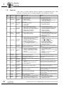
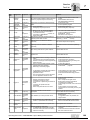
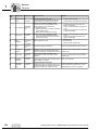
7.1 Fault information ........................................................................................ 131
7.2 Fault list...................................................................................................... 132
7.3 SEW Electronics Service ........................................................................... 135
7.4 Extended storage ....................................................................................... 136
7.5 Waste disposal........................................................................................... 136
8 Technical Data and Dimension Drawings ........................................................ 137
8.1 CE marking, UL approval and unit designation.......................................... 137
8.2 General technical data ............................................................................... 138
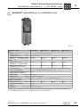
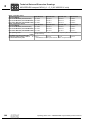
8.3 MOVIDRIVE® compact MCH4_A...-5_3 (AC 400/500 V units) .................. 139
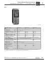
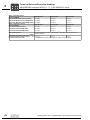
8.4 MOVIDRIVE® compact MCH4_A...-2_3 (AC 230 V units) ......................... 149
8.5 MOVIDRIVE® compact MCH electronics data........................................... 157
8.6 MOVIDRIVE® compact dimension drawings ............................................. 160
9 Index .................................................................................................................... 165
4
Operating Instructions – MOVIDRIVE® compact MCH4_A Drive Inverters
Structure of the Safety Notes
1
1
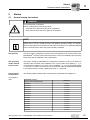
Structure of the Safety Notes
Betriebsanleitung
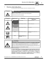
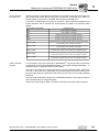
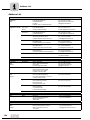
The safety notes in these operating instructions are designed as follows:
Pictogram
SIGNAL WORD!
Type and source of danger.
Possible consequence(s) if the safety notes are disregarded.
•
Pictogram
Example:
Measure(s) to prevent the danger.
Signal word
Meaning
Consequences in case of
disregard
DANGER!
Imminent danger
Severe or fatal injuries
WARNING!
Possible dangerous situation
Severe or fatal injuries
CAUTION!
Possible dangerous situation
Minor injuries
STOP!
Possible damage to property
Damage to the drive system or its
environment
NOTE
Useful information or a tip
Simplifies the handling of the
drive system
General danger
Specific danger,
e.g. electric shock
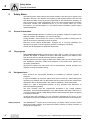
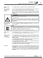
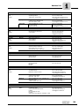
CAUTION!
A requirement of fault-free operation and fulfillment of any rights to claim under
limited warranty is that you adhere to the information in the operating instructions.
Therefore, read the operating instructions before you start operating the unit!
Make sure that the operating instructions are available to persons responsible for the
plant and its operation, as well as to persons who work independently on the unit. You
must also ensure that the documentation is legible.
Exclusion of liability:
You must comply with the information contained in these operating instructions
to ensure safe operation of the MOVIDRIVE® compact drive inverters and to
achieve the specified product characteristics and performance requirements.
SEW-EURODRIVE assumes no liability for injury to persons or damage to
equipment or property resulting from non-observance of these operating
instructions. In such cases, any liability for defects is excluded.
Operating Instructions – MOVIDRIVE® compact MCH4_A Drive Inverters
5
Safety Notes
General information
2
2
Safety Notes
The following basic safety notes must be read carefully to prevent injury to persons and
damage to property. The operator must make sure that the basic safety notes are read
and observed. Make sure that persons responsible for the plant and its operation, as
well as persons who work independently on the unit, have read through the operating
instructions carefully and understood them. If you are unclear about any of the
information in this documentation, or if you require further information, please contact
SEW-EURODRIVE.
2.1
General information
Never install damaged products or take them into operation. Submit a complaint to the
shipping company immediately in the event of damage.
During operation, drive inverters can have live, bare and movable or rotating parts as
well as hot surfaces, depending on their enclosure.
Removing covers without authorization, improper use or incorrect installation and
operation may result in severe injuries to persons or damage to machinery.
Consult the documentation for additional information.
2.2
Target group
Only qualified personnel are authorized to install, start up, repair or service the units
(observe IEC 60364 or CENELEC HD 384 or DIN VDE 0100 and IEC 60664 or DIN
VDE 0110 as well as national accident prevention guidelines).
Qualified personnel in the context of these basic safety notes are: all persons familiar
with installation, assembly, startup and operation of the product who possess the
necessary qualifications.
All persons involved in any other work, such as transportation, storage, operation and
disposal, must have suitable training.
2.3
Designated use
Drive inverters are components intended for installation in electrical systems or
machines.
In case of installation in machines, startup of the drive inverters (i.e. start of designated
operation) is prohibited until it is determined that the machine meets the requirements
stipulated in the EC Directive 98/37/ EC (machine guideline); observe EN 60204.
Startup (i.e. start of designated operation) is only permitted with adherence to
EMC (89/336/EEC) guideline.
The drive inverters meet the requirements stipulated in low voltage guideline
73/23/EEC. The harmonized standards of the EN 61800-5-1/DIN VDE T105 series in
connection with EN 60439-1/VDE 0660 part 500 and EN 60146/VDE 0558 are applied
to these drive inverters.
Technical data and information on the connection requirements are given on the
nameplate and in the documentation; they have to be observed under all circumstances.
Safety functions
6
The MOVIDRIVE® compact drive inverters may not perform safety functions without
higher-level safety systems. Use higher-level safety systems to ensure protection of
personnel and equipment.
Operating Instructions – MOVIDRIVE® compact MCH4_A Drive Inverters
Safety Notes
Transportation, putting into storage
2.4
2
Transportation, putting into storage
Observe the notes on transportation, storage and proper handling. Observe the climatic
conditions as stated in the section "General technical data."
2.5
Installation
Installation and cooling of the devices must take place according to the guidelines listed
in the corresponding documentation.
Protect the drive inverters from excessive strain. Especially during transportation and
handling, do not allow the components to be deformed or insulation spaces altered.
Avoid contact with electronic components and contacts.
Drive inverters contain components that can be damaged by electrostatic energy and
improper handling. Prevent mechanical damage or destruction of electric components
(may pose health risk!)
The following applications are prohibited unless measures are expressly taken to make
them possible:
2.6
•
Use in potentially explosive atmospheres
•
Use in areas exposed to harmful oils, acids, gases, vapors, dust, radiation, etc.
•
Use in non-stationary applications that are subject to mechanical vibration and shock
loads in excess of the requirements in EN 50178
Electrical connection
Observe the applicable national accident prevention guidelines when working on live
drive inverters (e.g. BGV A3).
Perform electrical installation according to the pertinent regulations (e.g. line cross
sections, fusing, protective conductor connection). For any additional information, refer
to the applicable documentation.
You will find notes on EMC-compliant installation, such as shielding, grounding,
arrangement of filters and routing of lines, in the documentation of the drive inverters.
Always observe these notes even with drive inverters bearing the CE marking. The
manufacturer of the system or machine is responsible for maintaining the limits
established by the EMC legislation.
Preventive measures and protection devices must correspond to the regulations in force
(e.g. EN 60204 or EN 61800-5-1).
Required preventive measures: Ground the unit.
2.7
Safe disconnection
The unit meets all requirements for safe disconnection of power and electronic
connections in accordance with EN 61800-5-1. All connected circuits must also satisfy
the requirements for safe disconnection.
Operating Instructions – MOVIDRIVE® compact MCH4_A Drive Inverters
7
Safety Notes
Operation
2
2.8
Operation
Systems with integrated drive inverters must be equipped with additional monitoring and
protection devices, if necessary, according to the applicable safety guidelines, such as
the law governing technical equipment, accident prevention regulations, etc. Changes
to the drive inverter using the operating software are permitted.
Do not touch live components or power connections immediately after disconnecting the
drive inverters from the supply voltage because there may still be some charged
capacitors. Note the respective reference plates on the drive inverter.
Keep all covers and doors closed during operation.
The fact that the status LED and other display elements are no longer illuminated does
not indicate that the unit has been disconnected from the power supply and no longer
carries any voltage.
Mechanical blocking or internal safety functions of the unit can cause a motor standstill.
Removing the cause of the problem or performing a reset can result in the drive restarting on its own. If, for safety reasons, this is not permitted for the driven machine,
disconnect the unit from the mains before correcting the fault.
8
Operating Instructions – MOVIDRIVE® compact MCH4_A Drive Inverters
Unit Design
Unit designation, nameplates and scope of delivery
3
Unit Design
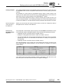
3.1
Unit designation, nameplates and scope of delivery
3
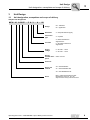
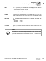
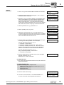
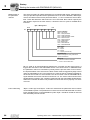
Sample unit designation
MCH 41 A 0055 - 5 A 3 - 4 - 00
Design
00 = Standard
0T = Application
Quadrants
4 = 4Q (with brake chopper)
Connection
type
3 = 3-phase
Line filter
Supply
voltage
Recommended motor
power
A = Radio interference
suppression A
0 = No radio interference
suppression
5 = AC 380 ... 500 V
2 = AC 200 ... 240 V
0055 = 5.5 kW
Version A
Series and
variants
40 = without fieldbus
41 = with PROFIBUS-DP
42 = with INTERBUS-LWL
Series
Operating Instructions – MOVIDRIVE® compact MCH4_A Drive Inverters
MCH = field-oriented with encoder
(Hiperface®, sin/cos or TTL) for
asynchronous and synchronous motor
9
Unit Design
Unit designation, nameplates and scope of delivery
3
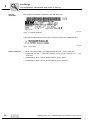
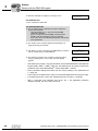
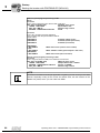
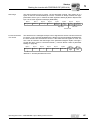
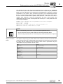
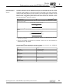
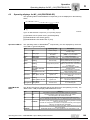
Sample
nameplate
The complete nameplate is attached to the side of the unit.
Figure 1: Complete nameplate
05230AXX
A type label is attached to the front of the control unit (above the TERMINAL slot).
05231AXX
Figure 2: Type label
Scope of delivery
10
•
MCH: Connector housing for all signal terminals (X10 ... X12), connected
•
Additionally for size 1: Connector housing for the power terminals (X1 ... X4),
connected
•
Additionally for sizes 1 and 2: Shield clamp for power section
•
Additionally for sizes 4 and 5: Touch guard for power terminals.
Operating Instructions – MOVIDRIVE® compact MCH4_A Drive Inverters
Unit Design
Size 1 MCH4_A
3.2
3
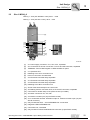
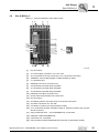
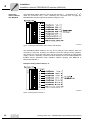
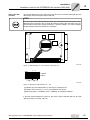
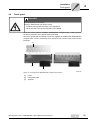
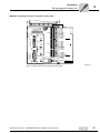
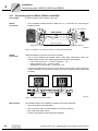
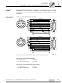
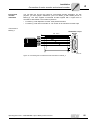
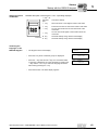
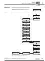
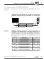
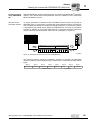
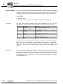
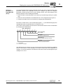
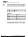
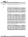
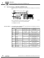
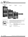
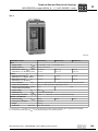
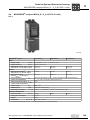
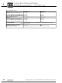
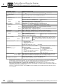
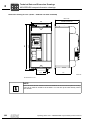
Size 1 MCH4_A
MCH4_A...-5A3 (AC 400/500 V units): 0015 ... 0040
MCH4_A...-2A3 (AC 230 V units): 0015 ... 0037
[1]
[2]
[3]
[4]
[5]
[6]
[7]
[19]
[18]
[17]
[16]
[8]
[20]
[9]
[15]
[10]
[11]
[14] [13][12]
60122AXX
[1]
X1: Power supply connection 1/L1, 2/L2, 3/L3, separable
[2]
X4: Connection for DC link connection –UZ/+UZ and PE connection, separable
[3]
TERMINAL: Slot for DBG keypad or USS21A/USB11A option
[4]
V1: Operation LED
[5]
Retaining screw A for connection unit
[6]
Panel on connection unit with label
[7]
X10: Electronics terminal strip, separable
[8]
X11: Electronics terminal strip, separable
[9]
X12: Electronics terminal strip, separable
[10] Retaining screw B for connection unit
[11] Screw of the shield clamp for the control unit
[12] X3: Braking resistor connection 8/+R, 9/–R and PE connection, separable
[13] Connection for shield clamp of the power section (not visible)
[14] X2: Motor connection 4/U, 5/V, 6/W
[15] X15: Motor encoder input (15-pole Sub-D socket)
[16] X14: Incremental encoder simulation output or external encoder input (15-pole
Sub-D connector)
[17] Only for MCH42A X30 ... X33: INTERBUS-LWL connections
[18] Diagnostic LEDs INTERBUS-LWL
[19] Connection unit, removable
[20] Only for MCH41A X30: PROFIBUS-DP connection (9-pole Sub-D socket)
Operating Instructions – MOVIDRIVE® compact MCH4_A Drive Inverters
11
Unit Design
Size 2 MCH4_A
3
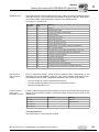
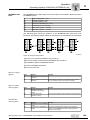
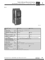
3.3
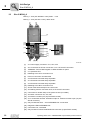
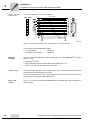
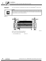
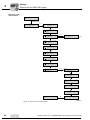
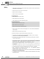
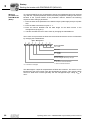
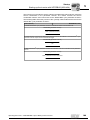
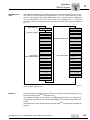
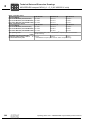
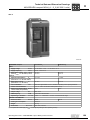
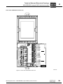
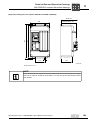
Size 2 MCH4_A
MCH4_A...-5A3 (AC 400/500 V units): 0055 ... 0110
MCH4_A...-2A3 (AC 230 V units): 0055 / 0075
[1]
[2]
[3]
[4]
[5]
[6]
[7]
[19]
[18]
[17]
[16]
[8]
[20]
[9]
[15]
[10]
[11]
[14]
[13] [12]
60124AXX
[1]
X1: Power supply connection 1/L1, 2/L2, 3/L3
[2]
X4: Connection for DC link connection –UZ/ +UZ/ and PE connection
[3]
TERMINAL: Slot for DBG keypad or USS21A/USB11A option
[4]
V1: Operation LED
[5]
Retaining screw A for connection unit
[6]
Panel on connection unit with label
[7]
X10: Electronics terminal strip, separable
[8]
X11: Electronics terminal strip, separable
[9]
X12: Electronics terminal strip, separable
[10] Retaining screw B for connection unit
[11] Screw of the shield clamp for the control unit
[12] X3: Braking resistor connection 8/+R, 9/–R and PE connection
[13] Connection for shield clamp of the power section (not visible)
[14] X2: Motor connection 4/U, 5/V, 6/W
[15] X15: Motor encoder input (15-pole Sub-D socket)
[16] X14: Incremental encoder simulation output or external encoder input (15-pole
Sub-D connector)
[17] Only for MCH42A X30 ... X33: INTERBUS-LWL connections
[18] Diagnostic LEDs INTERBUS-LWL
[19] Connection unit, removable
[20] Only for MCH41A X30: PROFIBUS-DP connection (9-pole Sub-D socket)
12
Operating Instructions – MOVIDRIVE® compact MCH4_A Drive Inverters
Unit Design
Size 3 MCH4_A
3.4
3
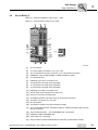
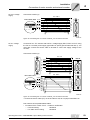
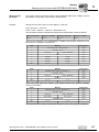
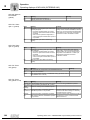
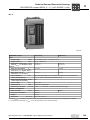
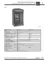
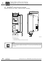
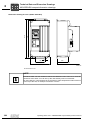
Size 3 MCH4_A
MCH4_A...-503 (AC 400/500 V units): 0150 ... 0300
MCH4_A...-203 (AC 230 V units): 0110 / 0150
[1]
[2]
[3]
[4]
[5]
[6]
[7]
[20]
[19]
[18]
[19]
[8]
[9]
[16]
[21]
[10]
[11]
[12]
[15]
[14]
[13]
60126AXX
[1]
PE connections
[2]
X1: Power supply connection 1/L1, 2/L2, 3/L3
[3]
X4: Connection for DC link connection –UZ/ +UZ/ and PE connection
[4]
TERMINAL: Slot for DBG keypad or USS21A/USB11A option
[5]
V1: Operation LED
[6]
Retaining screw A for connection unit
[7]
X10: Electronics terminal strip, separable
[8]
X11: Electronics terminal strip, separable
[9]
X12: Electronics terminal strip, separable
[10] Retaining screw B for connection unit
[11] Screw of the shield clamp for the control unit
[12] Panel on connection unit with label
[13] X3: Braking resistor connection 8/+R, 9/–R and PE connection
[14] X2: Motor connection 4/U, 5/V, 6/W
[15] PE connections
[16] X15: Motor encoder input (15-pole Sub-D socket)
[17] X14: Incremental encoder simulation output or external encoder input (15-pole
Sub-D connector)
[18] Only for MCH42A X30 ... X33: INTERBUS-LWL connections
[19] Diagnostic LEDs INTERBUS-LWL
[20] Connection unit, removable
[21] Only for MCH41A X30: PROFIBUS-DP connection (9-pole Sub-D socket)
Operating Instructions – MOVIDRIVE® compact MCH4_A Drive Inverters
13
Unit Design
Size 4 MCH4_A
3
3.5
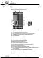
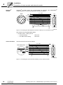
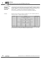
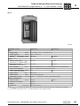
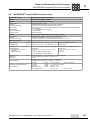
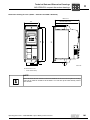
Size 4 MCH4_A
MCH4_A...-503 (AC 400/500 V units): 0370 / 0450
MCH4_A...-203 (AC 230 V units): 0220 / 0300
[1]
[2]
[3]
[1]
[4]
[5]
[6]
[7]
[19]
[18]
[17]
[16]
[8]
[9]
[15]
[20]
[10]
[11]
[12] [14]
[13]
[12]
60131AXX
[1]
PE connections
[2]
X1: Power supply connection 1/L1, 2/L2, 3/L3
[3]
X4: Connection for DC link connection –UZ/ +UZ/ and PE connection
[4]
TERMINAL: Slot for DBG keypad or USS21A/USB11A option
[5]
V1: Operation LED
[6]
Retaining screw A for connection unit
[7]
X10: Electronics terminal strip, separable
[8]
X11: Electronics terminal strip, separable
[9]
X12: Electronics terminal strip, separable
[10] Retaining screw B for connection unit
[11] Screw of the shield clamp for the control unit
[12] PE connections
[13] X3: Braking resistor connection 8/+R, 9/–R and PE connection
[14] X2: Motor connection 4/U, 5/V, 6/W
[15] X15: Motor encoder input (15-pole Sub-D socket)
[16] X14: Incremental encoder simulation output or external encoder input (15-pole
Sub-D connector)
[17] Only for MCH42A X30 ... X33: INTERBUS-LWL connections
[18] Diagnostic LEDs INTERBUS-LWL
[19] Connection unit, removable
[20] Only for MCH41A X30: PROFIBUS-DP connection (9-pole Sub-D socket)
14
Operating Instructions – MOVIDRIVE® compact MCH4_A Drive Inverters
Unit Design
Size 5 MCH4_A
3.6
3
Size 5 MCH4_A
MCH4_A...-503 (AC 400/500 V units): 0550 / 0750
[1]
[2]
[3]
[1]
[4]
[5]
[6]
[7]
[19]
[18]
[17]
[16]
[8]
[9]
[15]
[20]
[10]
[11]
[12] [14]
[13]
[12]
60134AXX
[1]
PE connections
[2]
X1: Power supply connection 1/L1, 2/L2, 3/L3
[3]
X4: Connection for DC link connection –UZ/ +UZ/ and PE connection
[4]
TERMINAL: Slot for DBG keypad or USS21A/USB11A option
[5]
V1: Operation LED
[6]
Retaining screw A for connection unit
[7]
X10: Electronics terminal strip, separable
[8]
X11: Electronics terminal strip, separable
[9]
X12: Electronics terminal strip, separable
[10] Retaining screw B for connection unit
[11] Screw of the shield clamp for the control unit
[12] PE connections
[13] X3: Braking resistor connection 8/+R, 9/–R and PE connection
[14] X2: Motor connection 4/U, 5/V, 6/W
[15] X15: Motor encoder input (15-pole Sub-D socket)
[16] X14: Incremental encoder simulation output or external encoder input (15-pole
Sub-D connector)
[17] Only for MCH42A X30 ... X33: INTERBUS-LWL connections
[18] Diagnostic LEDs INTERBUS-LWL
[19] Connection unit, removable
[20] Only for MCH41A X30: PROFIBUS-DP connection (9-pole Sub-D socket)
Operating Instructions – MOVIDRIVE® compact MCH4_A Drive Inverters
15
Installation
Installation instructions for the basic unit
4
4
Installation
4.1
Installation instructions for the basic unit
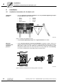
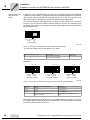
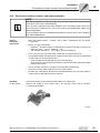
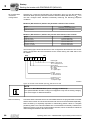
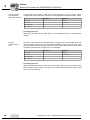
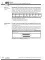
Tightening
torques
•
Only use genuine connection elements. Note the permitted tightening torques
for MOVIDRIVE® power terminals.
–
–
–
–
Size 1
Size 2
Size 3
Sizes 4 and 5
→
→
→
→
0.6 Nm
1.5 Nm
3.5 Nm
14 Nm
Nm!
59847AXX
Figure 3: Observe the tightening torques
Minimum
clearance and
mounting
position
•
The permitted tightening torque of the signal terminals is 0.6 Nm.
•
Leave 100 mm clearance at the top and bottom for optimum cooling. There is no
need for clearance at the sides. You can line up the units directly next to one another.
With sizes 4 and 5 do not install any components that are sensitive to high
temperatures within 300 mm of the top of the unit. Only install the units vertically.
You must not install them horizontally, tilted or upside down.
100 mm
E
Q
E
Q
E
Q
E
Q
100 mm
Figure 4: Minimum clearance and mounting position of the units
16
60136AXX
Operating Instructions – MOVIDRIVE® compact MCH4_A Drive Inverters
Installation
Installation instructions for the basic unit
Separate cable
ducts
•
Route power cables and electronics cables in separate cable ducts.
Fuses and earthleakage circuit
breakers
•
Install the fuses at the beginning of the supply system lead after the supply bus
junction (→ Wiring diagram for basic unit, power section and brake).
•
SEW-EURODRIVE recommends that you do not use earth-leakage circuit breakers.
However, if an earth-leakage circuit breaker is stipulated for direct or indirect
protection against contact, observe the following information in accordance with
EN 61800-5-1:
4
WARNING!
Incorrect earth-leakage circuit breaker installed.
Severe or fatal injuries.
MOVIDRIVE® can cause direct current in the protective earth. In cases where an earthleakage circuit breaker is used for protection against direct or indirect contact, only
install a type B earth-leakage circuit breaker on the power supply end of the
MOVIDRIVE® unit.
Mains and brake
contactors
•
Only use contactors in utilization category AC-3 (EN 60947-4-1) as mains and
brake contactors.
NOTES
•
Only use the mains contactor K11 (→ Sec. "Wiring diagram for basic unit") to
switch the inverter on and off. Do not use it for jog mode. Use the commands
"Enable/Stop", "CW/Stop" or "CCW/Stop" for jog mode.
•
Observe a minimum switch-off time of 10 s for the input contactor K11.
More than four
units
•
With more than four units on an input contactor configured for the total current:
Insert a 3-phase line choke in the circuit to limit the inrush current.
PE power supply
connection
(→ EN 61800-5-1)
•
For a supply system lead < 10 mm2: Route a second PE conductor with the
cross section of the supply system lead parallel to the protective earth via
separate terminals or use a copper protective earth conductor with a cross
section of 10 mm2.
•
For a supply system lead 10 mm2 ... 16 mm2: Route a copper protective earth
conductor with the cross section of the power supply line.
•
For a supply system lead 16 mm2 ... 35 mm2: Route a copper protective earth
conductor with the cross section of 16 mm2.
•
For a supply system lead > 35 mm2: Route a copper protective earth conductor
with half the cross section of the power supply line.
•
SEW-EURODRIVE recommends using earth-leakage monitors with pulse-code
measurement for voltage supply systems with a non-grounded star point
(IT systems). Using such devices prevents the earth-leakage monitor mis-tripping
due to the ground capacitance of the inverter. No EMC limits are specified for
interference emission in voltage supply systems without grounded star point
(IT systems).
IT systems
Operating Instructions – MOVIDRIVE® compact MCH4_A Drive Inverters
17
Installation
Installation instructions for the basic unit
4
Cross sections
•
Supply system lead: Cross section according to rated input current Imains at rated
load.
•
Motor lead: Cross section according to rated output current Irated.
•
Electronics cables for MCH:
– Only single cores 0.20...1.5 mm2 (AWG 24...12)
– Use right-angled crimping pliers with 1.5 mm2 (AWG 16)
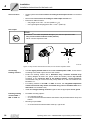
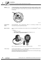
Unit output
STOP!
MOVIDRIVE® can suffer irreparable damage if you connect capacitive loads.
•
Only connect ohmic/inductive loads (motors).
•
Never connect capacitive loads.
E
Q
Figure 5: Only connect ohmic/inductive loads; do not connect capacitive loads
Connecting
braking resistors
Installing braking
resistors BW... /
BW..-T / BW...-P
60135AXX
•
Use two tightly twisted leads or a 2-core shielded power cable. Cross section
according to the rated output current of the inverter.
•
Protect the braking resistor with a bimetallic relay / thermal overload relay
(→ Wiring diagram for basic unit, power section and brake). Set the trip current
according to the technical data of the braking resistor. SEW-EURODRIVE
recommends using an overcurrent relay of trip class 10 or 10A in accordance with
EN 60947-4-1.
•
For braking resistors of the BW...-T / BW...-P series, the integrated temperature
switch/overcurrent relay can be connected using a 2-core shielded cable as an
alternative to a bimetallic relay.
•
Install the flat-type braking resistors together with the appropriate touch guard.
•
Permitted mounting options:
– on horizontal surfaces
– on vertical surfaces with brackets at the bottom and perforated sheets at top and
bottom
•
Mounting not permitted:
– on vertical surfaces with brackets at the top, right or left
18
Operating Instructions – MOVIDRIVE® compact MCH4_A Drive Inverters
Installation
Installation instructions for the basic unit
Operating
braking resistors
•
4
The connection leads to the braking resistors carry a high pulsed DC voltage during
rated operation.
WARNING!
The surfaces of the braking resistors get very hot when the braking resistors are loaded
with Prated.
Risk of burns and fire.
•
Choose a suitable installation location. Braking resistors are usually installed on top
of the control cabinet.
•
Do not touch the braking resistors.
Binary inputs /
binary outputs
•
The binary inputs are electrically isolated by optocouplers.
•
The binary outputs are short-circuit proof and protected against external
voltage to DC 30 V. External voltages > DC 30 V can cause irreparable damage to
binary outputs.
EMC compliant
installation
•
Only use shielded control cables.
•
All cables except for the supply system lead must be shielded. As an alternative to
shielding, the HD.. output choke option can be used for the motor cable to achieve
the emitted interference limit values.
•
When using shielded motor cables, e.g. prefabricated motor cables from
SEW-EURODRIVE, you must keep the unshielded conductors between the
shield and connection terminal of the inverter as short as possible.
•
Apply the shield by the shortest possible route and make sure it is grounded
over a wide area at both ends. Ground one end of the shield via a suppression
capacitor (220 nF / 50 V) to avoid ground loops. If using double-shielded cables,
ground the outer shield on the controller end and the inner shield on the other end.
Figure 6: Correct shield connection using metal clamp (shield clamp) or cable gland
60028AXX
•
You can also use grounded sheet-metal ducts or metal pipes to shield the
cables. Route the power and control cables separately.
•
Provide high frequency compatible grounding for the inverter and all additional
units (wide area metal-on-metal contact between the unit housing and ground, e.g.
unpainted control cabinet mounting panel).
Operating Instructions – MOVIDRIVE® compact MCH4_A Drive Inverters
19
Installation
Installation instructions for the basic unit
4
NOTE
Line filter
Interference
emission
20
•
This is a product with restricted availability in accordance with IEC 61800-3. It may
cause interference in residential environments. In this case, the operator may need
to implement appropriate measures.
•
For detailed information on EMC compliant installation, refer to the publication
"Electromagnetic Compatibility in Drive Engineering" from SEW-EURODRIVE.
•
Sizes 1 and 2 are fitted with a line filter as standard. This line filter ensures that
limit value class A is maintained on the supply side. Use an NF...-... line filter as
an option to maintain the class B limit.
•
The NF...-... input filter option is required for sizes 3 to 5 to maintain class A and
B limits.
•
Install the line filter close to the inverter but outside the minimum clearance for
cooling.
•
Do not switch between the line filter and MOVIDRIVE®.
•
Keep the length of the cable between the line filter and inverter to an absolute
minimum, and never more than 400 mm. Unshielded, twisted cables are sufficient.
Use also unshielded lines for the supply system lead.
•
This line filter must be mounted either directly at the entry point into the switch
cabinet or close to the inverter if several inverters are connected to the same
line filter. The line filter must be chosen on the basis of the total current of the
connected inverters.
•
No EMC limits are specified for interference emission in voltage supply
systems without earthed star point (IT systems). The effectiveness of line filters
in IT systems is severely limited.
SEW-EURODRIVE recommends the following EMC measures on the output side to
maintain the class A and B limits:
•
Shielded motor cable
•
HD... output choke option
Operating Instructions – MOVIDRIVE® compact MCH4_A Drive Inverters
Installation
Installation instructions for the basic unit
HD... output choke
4
•
Install the output choke close to the inverter but outside the minimum clearance
for cooling.
•
Route all three phases of the motor cable [1] through the output choke. To
achieve a higher filter effect, do not route the PE conductor through the output
choke.
4
5
6
®
MOVIDRIVE
n=5
HD...
PE U V W
[1]
60029AXX
[1] Motor cable
Operating Instructions – MOVIDRIVE® compact MCH4_A Drive Inverters
21
Installation
Installation notes for PROFIBUS-DP interface (MCH41A)
4
4.2
Installation notes for PROFIBUS-DP interface (MCH41A)
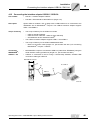
Pin assignment
For connection to the PROFIBUS network, use a 9-pole Sub-D connector in accordance
with IEC 61158 (→ following figure). The T-bus connection must be made using a plug
with the corresponding configuration.
02893AEN
®
As a rule, the MOVIDRIVE compact drive inverter is connected to the PROFIBUS
system using a shielded twisted-pair cable. Observe the maximum supported
transmission rate when selecting the bus connector.
The twisted-pair cable is connected to the PROFIBUS connector using pins 3
(RxD/TxD-P) and 8 (RxD/TxD-N). Communication takes place via these two contacts.
The RS485 signals RxD/TxD-P and RxD/TxD-N must be connected to the same
contacts in all PROFIBUS stations. Otherwise, no communication is possible via the bus
medium. The PROFIBUS interface sends a TTL control signal for a repeater or fiber
optic adapter (reference = pin 9) via pin 4 (CNTR-P).
22
Operating Instructions – MOVIDRIVE® compact MCH4_A Drive Inverters
Installation
Installation notes for PROFIBUS-DP interface (MCH41A)
Shielding and
routing bus
cables
4
The PROFIBUS interface supports RS485 transmission technology and requires the
cable type A to IEC 61158 specified as the physical medium for PROFIBUS. This cable
must be a shielded, twisted-pair cable.
Correct shielding of the bus cable attenuates electrical interference that may occur in
industrial environments. The following measures ensure the best possible shielding:
•
Manually tighten the mounting screws on the connectors, modules, and equipotential
bonding conductors.
•
Use only connectors with a metal housing or a metallized housing.
•
Connect the shielding in the connector over a wide surface area.
•
Apply the shielding of the bus line on both ends.
•
Route signal and bus cables in separate cable ducts. Do not route them parallel to
power cables (motor leads).
•
Use metallic, grounded cable racks in industrial environments.
•
Route the signal cable and the corresponding equipotential bonding close to each
other using the shortest possible route.
•
Avoid using plug connectors to extend bus cables.
•
Route the bus cables closely along existing grounding surfaces.
NOTE
In case of fluctuations in the ground potential, a compensating current may flow via the
bilaterally connected shield that is also connected to the protective earth (PE). Make
sure you supply adequate equipotential bonding according in accordance with relevant
VDE regulations in such a case.
Bus termination
for MCH41A
MCH41A is not provided with bus terminating resistors. This enables the bus system to
be taken into operation more easily and reduces the number of error sources.
Use a connector with an integrated bus terminating resistor if the inverter is at the
beginning or end of a PROFIBUS segment and only one PROFIBUS cable leads to the
inverter.
Switch on the bus terminating resistors for this PROFIBUS connector.
Operating Instructions – MOVIDRIVE® compact MCH4_A Drive Inverters
23
Installation
Installation notes for PROFIBUS-DP interface (MCH41A)
4
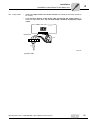
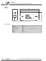
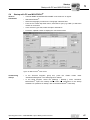
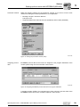
Setting the
station address
with MCH41A
The PROFIBUS station address is set using DIP switches 1 ... 8 (significance 20... 26)
under the connection unit (→ Sec. "Removing the connection unit" on page 38).
MOVIDRIVE® compact supports the address range 0 to 125.
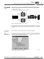
Figure 7: Setting the PROFIBUS station address with MCH41A
05527AEN
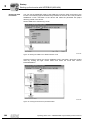
The PROFIBUS station address can only be set using the DIP switches when the
connection is removed. Therefore, the address cannot be changed during operation.
The change only comes into effect when the drive inverter is switched on again (power
supply + DC 24 V OFF/ON). The drive inverter displays the current station address in
fieldbus monitor parameter P092 "Fieldbus address" (display with DBG11B or
MOVITOOLS/SHELL).
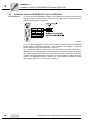
Example: Setting station address 17
Figure 8: Setting station address 17
24
05528AEN
Operating Instructions – MOVIDRIVE® compact MCH4_A Drive Inverters
Installation
Installation notes for the INTERBUS-LWL interface (MCH42A)
4.3
4
Installation notes for the INTERBUS-LWL interface (MCH42A)
Bus connection
via fiber optic
cable (LWL)
The bus connection is made using a fiber optic cable. Polymer fiber cables and HCS
cables may be used for this purpose.
Polymer fiber
cables
This type of cable is used for distances of up to 70 meters between two INTERBUS
participants. Depending on the system, several designs are available. This type of cable
is characterized by simple and cost-effective installation.
HCS cable
This type of cable can be used for distances up to 500 m because they are characterized
by considerably lower attenuation compared to polymer fibers.
The bus cable must be at least 1 m long. For shorter distances, use cable jumpers from
Phoenix Contact.
NOTE
For more information on proper routing of fiber optic cables, please refer to the Fiber
Optic Installation Guidelines from Phoenix Contact (item designation IBS SYS FOC
ASSEMBLY).
Check list for installing fiber optic cables
Installing fiber optic
cables
•
Do not exceed the maximum cable length
•
Observe the permitting bending radii
•
Do not squeeze or bend fiber optic cables
•
Do not exceed the tensile load when installing the cable
•
The optical fiber cable must be uncoiled using an uncoiling device
•
Protect fiber optic cables against strain and impermissibly small bending radii
•
Install the cables without loops
•
Protect cables against sharp edges
•
Use a special cable type if fiber optic cables are installed in special areas (e.g. in the
ground or close to welding robots)
•
Strip off the outer cable sheath and the individual wire without damaging them
•
Fix the individual wire in the connector (strain relief)
•
Polish and install the front of the connector according to the guidelines
Measuring fiber
optic cables
•
Check whether the light intensity complies with the limit values (optical diagnostics
using CMD tool or fiber-optic measuring instrument)
Connecting fiber
optic connectors
The fiber optic cable is connected to MOVIDRIVE® compact MCH42A using F-SMA
connectors. Two connectors are required each for the incoming and outgoing remote
bus (transmitter and receiver). SEW-EURODRIVE recommends using F-SMA
connectors with bending protection to ensure that the optimum bending radius is
maintained.
Order information
F-SMA connector (e.g. Phoenix Contact).
Protective
measures for fiber
optic cables
Prefabricating fiber
optic cables
Article designation
Designation
F-SMA connector set for polymer fiber cables (4 connectors) with bending protection
PSM-SET-FSMA/4-KT
Operating Instructions – MOVIDRIVE® compact MCH4_A Drive Inverters
25
Installation
Installation notes for the INTERBUS-LWL interface (MCH42A)
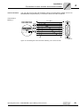
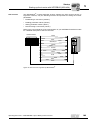
INTERBUS remote bus with fiber optic cable
X30
X31
X32
Direction
Wire color of FO
cable
FO Remote IN
(Incoming remote bus)
Receive data
Orange (OG)
Send data
Black (BK)
FO Remote OUT
(outgoing remote bus)
Receive data
Black (BK)
Send data
Orange (OG)
UL
CC
BA
RD
TR
FO1
FO2
X33
Signal
X10
X30
X14
OG
X31
BK
X11
1
2
3
4
5
6
7
8
9
X12
1
2
3
4
5
6
7
X32
X15
BK
X33
1
2
3
4
5
6
7
8
9
10
11
UL
CC
BA
RD
TR
FO1
FO2
Connection
X30
OG
X14
Pin assignment
X31
BK
X32
X15
4
X33
OG
Figure 9: FO connection assignment
Use fiber optic cables of different lengths to prevent the fiber optic cables from bending.
Observe the length data in the following figure.
X
+
18
mm
Length of the fiber
optic cable
05208AXX
X
+
18
mm
X
X
Figure 10: Different lengths of the fiber optic cables
26
50589BXX
Operating Instructions – MOVIDRIVE® compact MCH4_A Drive Inverters
Installation
Installation notes for the INTERBUS-LWL interface (MCH42A)
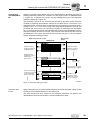
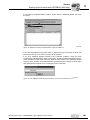
Setting the DIP
switches
4
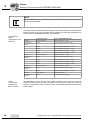
The six DIP switches S1 to S1 under the connection unit are used for setting the process
data length, the PCP length and the baud rate.
STOP!
You can only access the DIP switches when the connection unit is removed (→ Sec.
"Removing the connection unit" on page 38). Before removing the connection unit, you
must disconnect the power supply and DC 24 V auxiliary voltage. You cannot change
the DIP switches when the system is in operation.
ON
ON
1
1
2
2
3
4
3
5
4
6
5
6
X1
Figure 11: DIP switches S1... S6 under the connection unit
1
05216AXX
4
ON
1
2
3
20 21 22
[1]
4
5
6
0.5 MBaud
2 MBaud
2
[2]
[3]
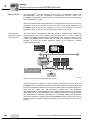
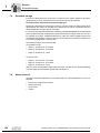
Figure 12: Settings for DIP switches S1 ... S6
05215AXX
[1] Number of process data items (1 to 6 PD), for example 2 PD
[2] Number of PCP words (1, 2 or 4), for example 2 PCP words
[3] Baud rate (ON = 0.5 MBaud, OFF = 2 MBaud), for example 2 MBaud
If the DIP switch settings are incorrect, the drive inverter responds with the ID code
"Microprocessor not ready" (38 hex).
Operating Instructions – MOVIDRIVE® compact MCH4_A Drive Inverters
27
4
Installation
Installation notes for the INTERBUS-LWL interface (MCH42A)
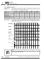
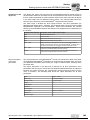
Setting the process
data and PCP
length
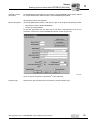
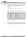
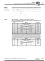
A maximum of six INTERBUS data words can be exchanged between the INTERBUS
interface and the inverter. These data words can be distributed between the process
data channel and the PCP channel using DIP switches S1 to S5. The restriction to six
data words results in settings that cannot be mapped onto the INTERBUS.
The inverter issues the "Microprocessor not ready" ID code (38hex) if the setting is
incorrect. The red TR LED indicates that the setting is incorrect. The following figure
shows the limit conditions for setting the process data length and PCP length with the
following restrictions:
1
4
4
5
ON
1
2
3
20 21 22
6
2
6 PD
[1]
ID: 03hex (3dez)
05217AXX
Figure 13: Settings for operating the inverter with 6 process data items
[1] The PCP settings with S4 and S5 are not in effect.
Process data length in words
PCP length
ID-Code
6
PCP setting not in effect;
no PCP channel available
03hex (3dec)
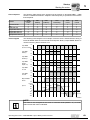
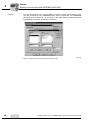
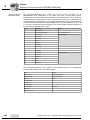
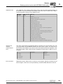
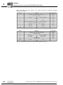
Examples:
1
4
1
ON
4
ON
1
2
3
20 21 22
5 PD
4
5
6
1
2
3
4
20 21 22
2
1 PCP
4 PD
ID: E3hex (227dez)
1
4
4
5
ON
5
6
1
2
3
20 21 22
2
2 PCP
2 PD
ID: E0hex (224dez)
6
2
4 PCP
ID: E1hex (225dez)
Figure 14: Examples for setting the PCP length and maximum process data length
05218AXX
PCP length
Maximum process data length
ID-Code
1 word
5 words
E3 hex (227dec)
2 words
4 words
E0 hex (224dec)
4 words
2 words
E1 hex (225dec)
If maximum length is exceeded or the
setting is 0 or 7 PD
38 hex (56dec) = "Microprocessor not
ready"
All settings not listed here result in the ID code "Microprocessor not ready." The inverter
then signals 0PD in parameter P090 "PD configuration" and indicates that the setting is
incorrect by means of the red TR LED.
28
Operating Instructions – MOVIDRIVE® compact MCH4_A Drive Inverters
Installation
UL compliant installation
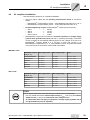
4.4
4
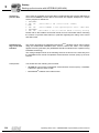
UL compliant installation
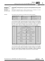
Note the following points for UL-compliant installation:
•
Only use copper cables with the following rated thermal values as connection
cables:
– MOVIDRIVE® compact MCH4_A0015 ... 0300: Rated thermal value 60 °C / 75 °C
– MOVIDRIVE® compact MCH4_A0370 ... 0750: Rated thermal value 75 °C
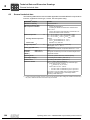
Permitted tightening torques for MOVIDRIVE® compact power terminals:
•
–
–
–
–
Size 1
Size 2
Size 3
Sizes 4 and 5
→
→
→
→
0.6 Nm
1.5 Nm
3.5 Nm
14 Nm
MOVIDRIVE® compact drive inverters are suited for operation on voltage supply
systems with grounded star point (TN and TT systems) that supply a maximum
current according to the following tables and have a max. voltage of AC 240 V for
MOVIDRIVE® compact MCH4_A...2_3 (AC 230 V units) and AC 500 V for
MOVIDRIVE® compact MCH4_A...-5_3 (AC 400/500 V units). The performance data
of the fuses must not exceed the values listed in the tables.
•
400/500 V units
MOVIDRIVE® compact
MCH4_A...5_3
Max. supply current
0015/0022/0030/0040
AC 10000 A
AC 500 V
AC 35 A / 600 V
0055/0075/0110
AC 5000 A
AC 500 V
AC 30 A / 600 V
0150/0220
AC 5000 A
AC 500 V
AC 175 A / 600 V
0300
AC 5000 A
AC 500 V
AC 225 A / 600 V
0370/0450
AC 10000 A
AC 500 V
AC 350 A / 600 V
0550/0750
AC 10000 A
AC 500 V
AC 500 A / 600 V
MOVIDRIVE® compact
MCH4_A...2_3
Max. supply current
Max. supply voltage
Fuses
0015/0022/0037
AC 5000 A
AC 240 V
AC 30 A / 250 V
0055/0075
AC 5000 A
AC 240 V
AC 110 A / 250 V
0110
AC 5000 A
AC 240 V
AC 175 A / 250 V
0150
AC 5000 A
AC 240 V
AC 225 A / 250 V
0220/0300
AC 10000 A
AC 240 V
AC 350 A / 250 V
Max. supply voltage
Fuses
230 V units
STOP!
The UL approval becomes void if the following conditions are not adhered to:
•
Use only tested units with a limited output voltage (Vmax = DC 30 V) and limited
output current (I ≤ 8 A) as an external DC 24 V voltage source.
•
UL certification does not apply to operation in voltage supply systems with a
non-grounded star point (IT systems).
Operating Instructions – MOVIDRIVE® compact MCH4_A Drive Inverters
29
Installation
Shield clamps
4
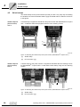
4.5
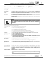
Shield clamps
The shield clamps for the power sections provide you with a very easy way of installing
the shield for the motor and brake cables. Apply the shield and PE conductor as shown
in the figures.
Shield clamp for
power section,
size 1
A shield clamp is supplied as standard for the power section with MOVIDRIVE® compact
size 1. Install this shield clamp together with the unit’s retaining screws.
[1]
[2]
02012CXX
Figure 15: Attaching the shield clamp of the power section (MOVIDRIVE® compact size 1)
Shield clamp for
power section,
size 2
[1]
Shield clamp
[2]
PE connection (댷)
A shield clamp for the power section is supplied as standard with two retaining screws
for MOVIDRIVE® compact size 2. Install these shield clamp using the two retaining
screws.
[1]
[2]
59874AXX
Figure 16: Attaching the shield clamp of the power section (MOVIDRIVE® compact size 2)
30
[1]
Shield clamp
[2]
PE connection (댷)
Operating Instructions – MOVIDRIVE® compact MCH4_A Drive Inverters
Installation
Touch guard
4.6
4
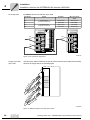
Touch guard
DANGER!
Uncovered power connections.
Severe or fatal injuries from electric shock.
•
Install the touch guard according to the regulations.
•
Never start the unit if the touch guard is not installed.
When the touch guard is installed, MOVIDRIVE® compact sizes 4 and 5 provide
enclosure protection IP10; without touch guard IP00.
Two touch guards with 8 retaining screws are supplied as standard with MOVIDRIVE®
compact sizes 4 and 5. Install the touch guard on both covers of the power section
terminals.
[2]
[1]
[3]
Figure 17: Touch guard for MOVIDRIVE® compact sizes 4 and 5
[1]
Cover
[2]
Connection plate
[3]
Aperture
Operating Instructions – MOVIDRIVE® compact MCH4_A Drive Inverters
06624AXX
31
Installation
Wiring diagram for basic unit
4
4.7
Wiring diagram for basic unit
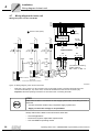
Wiring the power section and brake
L1
L2
L3
PE
F11/F12/F13
K11
(AC-3)
Protective earth (shield)
L1 L2
V AC
V AC
V AC
F14/F15
F14/F15
L3
NF... line filter option
L1' L2' L3'
1
F14/F15
2
DC link
connection*
3
7
L1 L2 L3
-UZ +UZ PE
X4:
X1:
K11
(AC-3)
K11
(AC-3)
Power section
K11
(AC-3)
X3:
X2:
DBØØ
DGND
DBØØ
DBØØ
K12
(AC-3)
1
BG 2
3
BGE 4
5
Brake connector
U
V
W
4
5
6
+R -R PE
8
9
K12
(AC-3)
DGND
1
BMK 2
3
4
13
14
15
8
see section "Connecting
braking resistors
BW... / BW..-T / BW...-P"
DGND
white
red
blue
CT/CV/DT/DV/D:
Cut-off in the DC and
AC circuits
1
BG 2
3
BGE 4
5
white
red
blue
M
3-phase
CT/CV/DT/DV/D:
Cut-off in the AC
circuit
CT/CV, CM71 ... 112: Cut-off in the DC and AC circuits
Figure 18: Wiring diagram, power section and brake
*
55310CEN
With sizes 1 and 2, there is no PE connection next to the supply system connection terminals and motor
connection terminals (X1, X2). In this case, use the PE terminal next to the DC link connection (X4).
Important: Read the operating instructions for the motors when connecting the brake.
STOP!
If the brake rectifier is connected via the supply system lead, the braking function is
restricted.
•
Connect the brake rectifier using a separate supply system lead.
•
Supply via the motor voltage is not permitted!
Always switch off the brake on the DC and AC sides with:
– All hoist applications
– Drives that require a rapid brake response time
– CFC and SERVO operating modes
32
Operating Instructions – MOVIDRIVE® compact MCH4_A Drive Inverters
Installation
Wiring diagram for basic unit
Brake rectifier in
control cabinet
4
Install the connection cables between the brake rectifier and the brake separately from
other power cables when installing the brake rectifier in the control cabinet. Joint
installation is only permitted with shielded power cables.
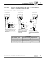
Connecting BW... / BW...-...-T /BW...-...-P braking resistors
Power section
Power section
X3:
X3:
+R -R PE
X3:
+R -R PE
8
8
+R -R
PE
Power section
9
9
F16
Has effect
on K11
BW...-...-P
97
F16
98
4
BW...-...-T
95
T2
RB1
Has effect
on K11
Has effect
on K11
96
T1
6
BW...
RB2
When the internal temperature switch
triggers, K11 must be opened and
DIØØ"/Controller inhibit assigned
a "0" signal. Do not interrupt the
resistor circuit!
When the auxiliary contact trips, K11 must
be opened and DIØØ"/Controller inhibit"
assigned a "0" signal. Do not interrupt the
resistor circuit!
When the external bimetallic relay
(F16) triggers, K11 must be opened
and DIØØ"/Controller inhibit" assigned
a "0" signal. Do not interrupt the resistor
circuit!
59500AEN
Overload protection
Braking resistor type
Design
specified
Internal temperature switch
(..T)
External bimetallic relay
(F16)
BW...
-
-
Required
BW...-...-T
-
One of the two options (internal temperature switch / external
bimetallic relay) is required.
BW...-003 / BW...-005
Adequate
-
Operating Instructions – MOVIDRIVE® compact MCH4_A Drive Inverters
Permitted
33
Installation
Wiring diagram for basic unit
4
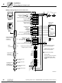
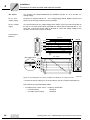
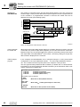
MCH4_A: Wiring diagram for the control unit
Control unit
+10 V
Optional
keypad
Optional
serial
interface
Output incremental
encoder simulation
or external
encoder input
0...10 V*, +/-10 V, n1
0...20 mA, 4...20 mA
n2(0...10 V)/TF/TH input*
Reference potential for analog signals
-10 V
System bus high
System bus low
Reference potential for binary signals
System bus high
System bus low
/Controller inhibit
CW/stop*
CCW/stop*
Enable/stop*
n11/n21*
n12/n22*
Reference X10: DIØØ...DIØ5
DC+24 V output
Reference potential for binary signals
X14:
Relay contact / brake
Ready*
N.O. contact relay
N.C. contact relay
No function*
DC+24 V input
Reference potential for binary signals
Motor
encoder input
X10:
REF1
AI11
AI12
AI21
AGND
REF2
SC11
SC12
DGND
SC21
SC22
R11
1
2
3
4
5
6
7
8
9
10
11
X11:
DIØØ
DIØ1
DIØ2
DIØ3
DIØ4
DIØ5
DCOM**
VO24
DGND
Binary input
Binary
outputs
Reference for
binary outputs
DGND
X12:
DBØØ 1
DOØ1-C 2
DOØ1-NO 3
DOØ1-NC 4
DOØ2/AO1 5
VI24
6
DGND 7
System bus terminating resistor
Change I-signal<-> U-signal*
K12
(AC-3)
DC 24 V
S12
S11
X31: LWL Remote IN
send data
X32: LWL Remote OUT
receive data
X33: LWL Remote OUT
send data
Settings
PROFIBUS-DP
only in MCH41A
INTERBUS-LWL
connections
(F-SMA connector)
only in MCH42A
Settings
INTERBUS
only in MCH42A
X31: LWL Remote IN
receive data
1
2
3
4
5
6
7
8
S6
S5
S4
S3
S2
S1
Protective earth (shield)
* Factory setting
** If the binary inputs are switched
by VO24 with DC 24 V, then
DCOM must be jumpered with
DGND !
Shield
terminal
X30:
AGND (Reference potential
DC 10 V analog signals)
DGND (reference potential
DC 24 V analog signals
ON OFF
PROFIBUS-DP
connection
only in MCH41A
Higher-level
controller
1
2
3
4
5
6
7
8
9
ON OFF
X15:
-10 V...+10 V
0(4)...20 mA
59872AEN
34
Operating Instructions – MOVIDRIVE® compact MCH4_A Drive Inverters
Installation
Wiring diagram for basic unit
•
MCH41A (with PROFIBUS-DP) / MCH42A (with INTERBUS-LWL):
SEW-EURODRIVE recommends that you always supply these units with DC 24 V at
terminal X10:24 (VI24). This external DC 24 V voltage supply must be able to provide
50 W continuous power and 100 W peak power (1s).
•
Analog input AI21 (X10:4) can be used either as a 10 V voltage input or as a TF/TH
input. It is switched over using parameter P120.
•
You can only access DIP switches S11, S12, 1 ... 8 and S1 ... S6 when the
connection unit is removed (→ Sec. "Removing the connection unit").
•
For an explanation of the function of DIP switches 1 ... 8, see the sections "Bus
termination for MCH41A" and "Setting the station address with MCH41A" on page 23
and page 24 .
•
The function of the DIP switches S1 ... S6 is explained in the section "DIP switch
settings."
•
The TF/TH line must either be shielded or routed at a distance of at least 0.2 m from
power cables (e.g. motor or brake cables). The TF/TH line must be separately
shielded if hybrid cables are used for the motor and TF/TH connection.
4
NOTE
TF can be connected to X15:6 and X15:14 or X10:1 and X10:4.
•
If TF is connected to X15, set P530 sensor type 1 to "TF/TH."
•
If TF is connected to X10, set P120 AI2 operating mode to "TF/TH."
With P835 Response TF signal you have to set the fault response.
Analog output
AO1
For MCH4_A, the binary output DOØ2 (X12:5) can also be used as 0(4)...20 mA analog
output AO1. Switch the settings with parameters P621 "Binary output DOØ2" and P642
"Operating mode AO1".
Function of X12:5
Binary output DOØ2
Analog output AO1
No function
P621 "Binary output DOØ2"
P642 "Operating mode AO1"
≠ set NO FUNCTION
= set OFF
= set NO FUNCTION
≠ set OFF
≠ set NO FUNCTION
≠ set OFF
= set NO FUNCTION
= set OFF
Operating Instructions – MOVIDRIVE® compact MCH4_A Drive Inverters
35
Installation
Wiring diagram for basic unit
4
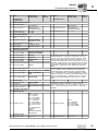
MCH4_A: Functional description of the terminals on the basic unit
Terminal
Function
X1:1/2/3
X2:4/5/6
X3:8/9
X4:
L1/L2/L3 (PE)
U/V/W (PE)
+R/-R (PE)
+UZ/-UZ (PE)
Power supply connection
Motor connection
Braking resistor connection
DC link connection
X10:1
X10:2/3
X10:4
X10:5
X10:6
REF1
AI11/12
AI21
AGND
REF2
DC+10 V (max. 3 mA) for setpoint potentiometer
Setpoint input n1 (differential input or input with AGND reference potential), signal form → P11_ / S11
Either setpoint input n2 (0...10 V) or TF/TH input, setting → P120
Reference potential for analog signals (REF1, REF2, AI..)
DC–10 V (max. 3 mA) for setpoint potentiometer
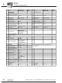
X10:7/8
SC11/SC12
X10:9
DGND
X10:10/11 SC21/SC22
System bus high/low, electrically connected with SC21/SC22 (X10:10/X10:11)
Reference potential system bus
System bus high/low, electrically connected with SC11/SC12 (X10:7/X10:8)
X11:1
X11:2
X11:3
X11:4
X11:5
X11:6
DIØØ
DIØ1
DIØ2
DIØ3
DIØ4
DIØ5
Binary input 1, with fixed assignment"/Controller inhibit" •
Binary input 2, factory setting "CW/stop"
Binary input 3, factory setting "CW/stop"
•
Binary input 4, factory setting to "Enable/Stop"
Binary input 5, factory setting "n11/n21"
Binary input 6, factory setting "n11/n22"
X11:7
DCOM
Reference for binary inputs DIØØ to DIØ5 (X11:1 to X11:6)
• Switching binary inputs with DC+24 V external voltage: DCOM (X11:7) must be connected to the
reference potential of the external voltage.
– Without jumper DCOM-DGND (X11:7-X11:9) → Isolated binary inputs
– With jumper DCOM-DGND (X11:7-X11:9) → Non-isolated binary inputs
X11:8
X11:9
VO24
DGND
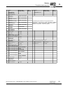
X12:1
DBØØ
•
The binary inputs are electrically isolated by
optocouplers.
Selection options for binary inputs 2 to 6 (DIØ1
... DIØ5) → Parameter menu P60_
Switching binary inputs with DC+24 V from VO24 (X11:8) → DCOM-DGND jumper required.
Auxiliary supply voltage DC+24 V (max. DC 200 mA) for external command switches
Reference potential for binary signals
Binary output 0, with fixed assignment "/Brake", max. load capacity DC 150 mA (short-circuit proof, protected
against external voltage to DC 30 V)
X12:2
DOØ1-C
Shared contact binary output 1, factory setting "Ready"
X12:3
DOØ1-NO
Normally open contact binary output 1, max. load capacity of relay contacts DC 30 V and DC 0.8 A
X12:4
DOØ1-NC
NC contact binary output 1
X12:5
DOØ2/AO1
Binary output 2, factory setting "No function," load capacity max. DC 50 mA (short-circuit proof, protected
against external voltage to DC 30 V), can also be used as analog output AO1, switch using P621 and P642
Selection options for binary outputs 1 and 2 (DOØ1 and DOØ2) → Parameter menu P62_
Do not apply external voltage to binary outputs DBØØ (X12:1) and DOØ2/AO1 (X12:5).
X12:6
VI24
Input DC+24 V voltage supply (backup voltage, unit diagnosis when supply system off)
X12:7
DGND
Reference potential for binary signals
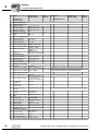
The following encoders can be connected as external encoders:
X14:1
Input for
Signal track A (K1)
• Hiperface encoder type AS1H, ES1H or AV1H
X14:2
external
Signal track B (K2)
• sin/cos encoder type ES1S, ES2S or EV1S
X14:3
encoder or
Signal track C (K0)
• 5 V TTL sensor with DC -24 V voltage supply type ES1R, ES2R or EV1R
X14:4
output for
DATA +
• 5 V TTL sensor with DC 5 V voltage supply type ES1T, ES2T or EV1T via
X14:5/6
incremental
Reserved
option DWI11A
X14:7
encoder sim- switchover
X14:8
ulation
Reference potential DGND If X14: is used as an incremental encoder simulation output, the switchover
X14:9
Signal track A (K1)
(X14:7) must be jumpered with DGND (X14:8).
Signal track B (K2)
X14:10
The DC 12 V supply voltage from X14 and X15 is sufficient to operate SEW
Signal track C (K0)
X14:11
encoders with a DC 24 V supply voltage.
DATA X14:12
Reserved
X14:13/14
DC+12 V (max. DC 180 mA)
X14:15
The following encoders can be connected:
X15:1
Motor
Signal track A (K1)
• Hiperface encoder type AS1H or ES1H
X15:2
encoder input Signal track B (K2)
• sin/cos encoder type ES1S, ES2S or EV1S
X15:3
Signal track C (K0)
• 5 V TTL sensor with DC -24 V voltage supply type ES1R, ES2R or EV1R
X15:4
DATA +
• 5 V TTL sensor with DC 5 V voltage supply type ES1T, ES2T or EV1T via
X15:5
Reserved
option DWI11A
X15:6
TF2
X15:7
Reserved
X15:8
Reference potential DGND The DC 12 V supply voltage from X14 and X15 is sufficient to operate SEW
X15:9
Signal track A (K1)
encoders with a DC 24 V supply voltage.
Signal track B (K2)
X15:10
Signal track C (K0)
X15:11
DATA X15:12
Reserved
X15:13
TF2
X15:14
DC+12 V (max. DC 180 mA)
X15:15
36
S1 ... S6
DIP switches for INTERBUS settings → Sec. "DIP switch settings" (page 27)
S11:
S12:
Change I-signal DC (0(4)...20 mA) ↔ U-signal DC (-10 V...0...10 V, 0...10 V), factory set to U signal.
Switch system bus terminating resistor on/off; factory setting: OFF.
TERMINAL
Slot for option DBG11B or options USS21A / USB11A
Operating Instructions – MOVIDRIVE® compact MCH4_A Drive Inverters
Installation
Wiring diagram for basic unit
4
X11
X15 Encoder IN
Remote OUT
X32 IN
X12
Remote OUT
X33 OUT
1
2
3
4
5
6
7
8
9
1
2
3
4
5
6
7
X10
X14 Encoder I/O
Remote IN
X31 OUT
1 REF1
2 AI11
3 AI12
4 AI21
5 AGND
6 REF2
7 SC11
8 SC12
9 DGND
10 SC21
11 SC22
X11
X10
Remote IN
X30 IN
1
2
3
4
5
6
7
8
9
10
11
1
2
3
4
5
6
7
8
9
DIØØ
DIØ1
DIØ2
DIØ3
DIØ4
DIØ5
DCOM
VO24
DGND
X12
UL
CC
BA
RD
TR
FO1
FO2
MCH42A: Assigning electronics terminals and the label
1
2
3
4
5
6
7
DBØØ
DOØ1-C
DOØ1-NO
DOØ1-NC
DOØ2
VI24
DGND
MCH 42A
Figure 19: Electronics terminals and label on MCH42A
Operating Instructions – MOVIDRIVE® compact MCH4_A Drive Inverters
max 24V !
(EN 61131-2)
59897AXX
37
Installation
Removing the connection unit
4
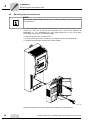
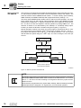
4.8
Removing the connection unit
NOTE
Turn off the supply voltage and DC 24 V auxiliary voltage before removing the
connection unit.
For simple installation of the control leads, remove the entire connection unit from the
control unit. You have to remove the connection unit to set the DIP switches for
PROFIBUS (1 ... 10), INTERBUS (S1...S6), signal switchover n1 (S11) and SBus
terminating resistor (S12). Proceed as follows:
1. Open the panel of the connection unit.
2. Loosen retaining screws A and B; they are captive screws and cannot fall out.
3. Remove the connection unit from the control module.
ON
OF
F
2
S11
S1
S
BULT
U
FA
N
RU
3.
2.
A
1.
2.
B
60111AXX
Follow the instructions in reverse order when installing the connection unit.
38
Operating Instructions – MOVIDRIVE® compact MCH4_A Drive Inverters
Installation
Assignment of braking resistors, chokes and filters
4.9
4
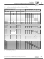
Assignment of braking resistors, chokes and filters
AC 400/500 V units, sizes 1 and 2
MOVIDRIVE® compact MC_4A...-5A3
0015
0022
Size
0030
0040
0055
1
Braking resistors
BW... / BW..-..-T
Trip current
Part number
BW...
BW100-005
IF = 0.8 ARMS
826 269 1
BW100-006/
BW100-006-T
IF = 2.4 ARMS
821 701 7
BW168/BW168-T
IF = 3.4 ARMS
820 604 X
1820 133 4
BW268/BW268-T
IF = 4.2 ARMS
820 715 1
1820 417 1
BW147/BW147-T
IF = 5 ARMS
820 713 5
1820 134 2
BW247/BW247-T
IF = 6.5 ARMS
820 714 3
1820 084 2
BW347/BW347-T
IF = 9.2 ARMS
820 798 4
1820 135 0
BW039-012/
BW039-012-T
IF = 5.5 ARMS
821 689 4
1820 136 9
BW039-026-T
IF = 8.1 ARMS
1820 415 5
BW039-050-T
IF = 11.3 ARMS
1820 137 7
Line chokes
0110
2
Part number
BW...-...-T
1820 419 8
Part number
ND020-013
Σ Imains = AC 20 A
826 012 5
ND045-013
Σ Imains = AC 45 A
826 013 3
Line filter
Part number
NF009-503
827 412 6
A
NF014-503
827 116 X
B
NF018-503
0075
Vmax = AC 550 V
NF035-503
A
B
827 413 4
827 128 3
Output chokes
Internal diameter
Part number
HD001
d = 50 mm
813 325 5
for cable cross sections 1.5 ... 16 mm2 (AWG 16 ... 6)
HD002
d = 23 mm
813 557 6
for cable cross sections ≤ 1.5 mm2 (AWG 16)
HD003
d = 88 mm
813 558 4
for cable cross sections > 16 mm2 (AWG 6)
Output filter (only in VFC operating
mode)
Part number
HF015-503
826 030 3
A
HF022-503
826 031 1
B
HF030-503
826,032 X
HF040-503
826 311 6
HF055-503
826 312 4
HF075-503
826 313 2
HF023-403
825 784 1
HF033-403
825 785 X
A
In rated operation (100 %)
B
With variable torque load (125 %)
Operating Instructions – MOVIDRIVE® compact MCH4_A Drive Inverters
A
B
A
B
A
B
A
B
A
B
A
B
39
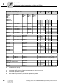
Installation
Assignment of braking resistors, chokes and filters
4
AC 400/500 V units, sizes 3 to 5
MOVIDRIVE® compact MC_4_A...-503
0150
Size
0300
0370
3
Braking
resistors
BW... /
BW...-...-T
BW...-...-P
Trip current
Part
number
BW...
BW018-015/
BW018-015-P
IF = 9.1 ARMS
821 684 3
BW018-035-T
IF = 13.9 ARMS
BW018-075-T
IF = 20.4 ARMS
BW915-T
IF = 32.6 ARMS
1820 413 9
BW012-025/
BW012-025-P
IF = 14.4ARMS
BW012-050-T
IF = 20.4 ARMS
1820 140 7
BW012-100-T
IF = 28.8 ARMS
1820 141 5
BW106-T
IF = 47.4 ARMS
1820 083 4
BW206-T
IF = 54.7 ARMS
1820 412 0
Line chokes
Part
number
BW...-...-T
Σ Imains = AC 45 A
ND085-013
ND150-013
0750
5
C
C
1820 138 5
C
C
1820 139 3
C
C
1820 416 3
821 680 0
0550
Part
number
BW...-...-P
1820 414 7
826 013 3
A
Σ Imains = AC 85 A
826 014 1
B
Σ Imains = AC 150 A
825 548 2
A
B
Part number
NF035-503
827 128 3
A
NF048-503
827 117 8
B
NF063-503
NF085-503
0450
4
Part number
ND045-013
Line filter
40
0220
827 414 2
Vmax = AC 550 V
A
B
NF115-503
827 416 9
NF150-503
827 417 7
NF210-503
827 418 5
A
B
827 415 0
A
B
A
B
Output chokes
Inside diameter
Part number
HD001
d = 50 mm
813 325 5
for cable cross sections 1.5...16 mm2 (AWG 16...6)
HD003
d = 88 mm
813 558 4
for cable cross sections > 16 mm2 (AWG 6)
Output filter
(only in VFC operating mode)
Part number
HF033-403
825 785 X
A
B/D
HF047-403
825 786 8
B
A
HF450-503
826 948 3
A
In rated operation (100 %)
B
With variable torque load (125 %)
C
Connect two braking resistors in parallel and set twice the trip current at F16 (2 x IF)
D
Connect two output filters in parallel
E
In rated operation (100 %): One output filter
With variable torque load (125 %): Connect two output filters in parallel
A/D
B
E
D
D
Operating Instructions – MOVIDRIVE® compact MCH4_A Drive Inverters
Installation
Assignment of braking resistors, chokes and filters
4
AC 230 V units, sizes 1 to 4
MOVIDRIVE® compact MC_4_A...-2_3
0015
Size
0022
0037
0055
1
0075
0110
2
0150
0220
3
0300
4
Braking
resistors
BW...-.../
BW...-...-T
Trip current
Part
number
BW...
BW039-003
IF = 2.7 ARMS
821 687 8
BW039-006
IF = 3.9 ARMS
821 688 6
BW039-012
BW039-012-T
IF = 5.5 ARMS
821 689 4
BW039-026-T
IF = 8.1 ARMS
BW027-006
IF = 4.7 ARMS
822 422 6
BW027-012
IF = 6.6 ARMS
822 423 4
BW018-015-T
IF = 9.1 ARMS
1 820 416 3
C
C
C
C
BW018-035-T
IF = 13.9 ARMS
1 820 138 5
C
C
C
C
BW018-075-T
IF = 20.4 ARMS
1 820 139 3
C
C
C
C
BW915-T
IF = 32.6 ARMS
1 820 413 9
C
C
C
C
BW012-025-T
IF = 14.4 ARMS
1 820 414 7
BW012-050-T
IF = 20.4 ARMS
1 820 140 7
BW012-100-T
IF = 28.8 ARMS
1 820 141 5
BW106-T
IF = 47.4 ARMS
1 820 083 4
C
C
BW206-T
IF = 54.7 ARMS
1 820 412 0
C
C
Line chokes
Part
number
BW...-...-T
1 820 136 9
1 820 415 5
Part number
ND020-013
Σ Imains = AC 20 A
826 012 5
A
ND045-013
Σ Imains = AC 45 A
826 013 3
B
ND085-013
Σ Imains = AC 85 A
826 014 1
ND150-013
Σ Imains = AC 150 A
825 548 2
Line filter
B
A
B
Part number
NF009-503
827 412 6
A
NF014-503
827 116 X
B
NF018-503
827 413 4
NF035-503
827 128 3
NF048-503
A
Vmax = AC 550 V
A
B
827 117 8
A
NF063-503
827 414 2
B
NF085-503
827 415 0
A
NF115-503
827 416 9
B
Output chokes
Inside diameter
Part number
HD001
d = 50 mm
813 325 5
for cable cross sections 1.5 ... 16 mm2
(AWG 16 ... 6)
HD002
d = 23 mm
813 557 6
for cable cross sections ≤ 1.5 mm2
(AWG 16)
HD003
d = 88 mm
813 558 4
for cable cross sections > 16 mm2
(AWG 6)
A
In rated operation (100 %)
B
With variable torque load (125 %)
C
Connect two braking resistors in parallel and set twice the trip current on F16 (2 × IF)
Operating Instructions – MOVIDRIVE® compact MCH4_A Drive Inverters
41
Installation
Installing the system bus (SBus)
4
4.10
Installing the system bus (SBus)
NOTE
Only if P884 "SBus baud rate" = 1000 kBaud:
Do not combine MOVIDRIVE® compact MCH4_A units with other MOVIDRIVE® units
in the same system bus system.
The units may be combined at baud rates ≠ 1000 kBaud.
Wiring diagram for SBus MOVIDRIVE® compact MCH4_A
Control unit
X10:
System bus high
System bus low
Reference potential
System bus high
System bus low
Control unit
Control unit
X10:
SC11
SC12
DGND
SC21
SC22
1
2
3
4
5
6
7
8
9
10
11
System bus high
System bus low
Reference potential
System bus high
System bus low
System bus ON OFF
Terminating resistor
S 12
S 11
SC11
SC12
DGND
SC21
SC22
X10:
1
2
3
4
5
6
7
8
9
10
11
System bus high
System bus low
Reference potential
System bus high
System bus low
System bus ON OFF
Terminating resistor
S 12
S 11
쵰
쵰
SC11
SC12
DGND
SC21
SC22
1
2
3
4
5
6
7
8
9
10
11
System bus ON OFF
Terminating resistor
S 12
S 11
쵰
쵰
05210AEN
SBus MCH4_A: Connect the terminating equipment to SC11/SC12. SC21/SC22 are
only active when S12 = OFF.
42
Operating Instructions – MOVIDRIVE® compact MCH4_A Drive Inverters
Installation
Installing the system bus (SBus)
Cable
specification
•
4
Use a 2-core twisted and shielded copper cable (data transmission cable with
braided copper shield). The cable must meet the following specifications:
– Core cross section 0.75 mm2 (AWG 18)
– Line resistance 120 Ω at 1 MHz
– Capacitance per unit length ≤ 40 pF/m at 1 kHz
Suitable cables include CAN bus or DeviceNet cables.
Shielding
•
Connect the shield at both ends to the electronics shield clamp of the inverter or the
master controller and ensure the shield is connected over a large area. Also connect
the ends of the shield to DGND.
Cable length
•
The permitted total cable length depends on the baud rate setting of the SBus
(P816):
–
–
–
–
Terminating
resistor
•
125 kBaud
250 kBaud
500 kBaud
1000 kBaud
→ 320 m
→ 160 m
→ 80 m
→ 40 m
Switch on the system bus terminating resistor (S12 = ON) at the start and end of the
system bus connection. Disconnect the terminating resistor at the other devices
(S12 = OFF).
STOP!
There must not be any potential displacement between the units connected with the
SBus. This can restrict the functionality of the units.
Take suitable measures to avoid a potential displacement, e.g. by connecting the unit
ground connectors using a separate lead.
Operating Instructions – MOVIDRIVE® compact MCH4_A Drive Inverters
43
Installation
Connecting option USS21A (RS232 and RS485)
4
4.11
Connecting option USS21A (RS232 and RS485)
Part number
Interface adapter option USS21A: 822 914 7
RS232
connection
•
Use a standard shielded interface cable with a 1:1 connection for connecting the
RS232 interface.
USS21A
PC COM 1-4
5
GND (ground)
5
3
2
TxD
3
2
RxD
max. 5 m (16.5 ft)
9-pin sub D connector (male)
9-pin sub D connector (female)
Figure 20: USS21A - PC connection cable (1:1 connection assignment)
RS485
connection
02399AEN
Read the following connection instructions carefully:
•
Use a 2-core twisted and shielded copper cable (data transmission cable with
braided copper shield). The cable must meet the following specifications:
– Core cross section 0.5 ... 0.75 mm2 (AWG 20 ... 18)
– Cable resistance 100 ... 150 Ω at 1 MHz
– Capacitance per unit length ≤ 40 pF/m at 1 kHz
•
Connect the shield at both ends to the electronics shield clamp of the inverter and
ensure the shield is connected over a large area. Also connect the ends of the shield
to DGND.
USS21A
0V5 -
+
1
쵰
2
3
1
2
3
쵰
USS21A
0V5 -
+
쵰
쵰
Figure 21: RS485 interface of USS21A
EIA standard
44
00997CXX
The RS485 interface of the USS21A complies with the EIA standard:
•
Max. transmission rate 9600 Baud
•
Max. 32 stations (each unit with USS21A counts as 2 stations)
•
Max. total cable length 200 m
•
Dynamic terminating resistor with fixed installation
Operating Instructions – MOVIDRIVE® compact MCH4_A Drive Inverters
Installation
Connecting the interface adapter USB11A / DKG11A
4.12
4
Connecting the interface adapter USB11A / DKG11A
Part number
•
824 831 1 Interface adapter USB11A
•
819 558 7 Serial interface cable DKG11A (length 3 m)
Description
Option USB11A enables a PC or laptop with a USB interface to be connected to the
TERMINAL slot of MOVIDRIVE® compact. The USB11A interface adapter supports
USB1.1 and USB2.0.
Scope of delivery
•
The scope of delivery for the USB11A includes:
– USB11A interface adapter
– USB connection cable PC - USB11A (type USB A-B)
– CD-ROM with drivers and MOVITOOLS®
•
The USB11A interface adapter supports USB 1.1 and USB 2.0.
•
The scope of delivery for the USB11A does not include:
– DKG11A connection cable (length 3 m, part number 819 558 7) for connecting
MOVIDRIVE® compact - USB11A.
Connecting
MOVIDRIVE® USB11A - PC
•
MOVIDRIVE® compact is connected to USB11A (cable RJ10-TERMINAL) using the
serial interface cable type DKG11A (length 3 m, part number 819 558 7).
•
USB11A is connected to the PC using a commercially available, shielded USB
connection cable type USB A-B.
MOVIDRIVE® compact
[1]
PC COM 1-4
[2]
[4]
[3]
USB11A
*
59901AXX
Operating Instructions – MOVIDRIVE® compact MCH4_A Drive Inverters
45
Installation
Connecting the interface adapter USB11A / DKG11A
4
Dimension
drawing
25
92.5
43
90
Figure 22: USB11A dimension drawing, dimensions in mm
55732BXX
Technical Data
USB11A
46
Part number
824 831 1
Ambient temperature
0 ... 40 °C
Storage temperature
–25 °C ... +70 °C (according to EN 60721-3-3, class 3K3)
Enclosure
IP20
Weight
300 g
Dimensions
92.5 x 43 x 25 mm
Operating Instructions – MOVIDRIVE® compact MCH4_A Drive Inverters
Installation
Connection of motor encoder and external encoder
4.13
4
Connection of motor encoder and external encoder
NOTE
The wiring diagrams do now show the view onto the cable end. They show the
connection to the motor or MOVIDRIVE®.
The core colors specified in the wiring diagrams are in accordance with the IEC 757
color code and correspond to the core colors used in the prefabricated cables from
SEW-EURODRIVE.
For more details, refer to the "SEW Encoder Systems" manual, which can be obtained
from SEW-EURODRIVE.
General
installation
instructions
•
Max. line length inverter - encoder: 100 m with a capacitance per unit length
≤ 120 nF/km.
•
MCH4_A: Core cross section
– Hiperface® encoders, sin/cos encoders and TTL sensors with DC 5 V supply (via
DWI11A): 0.25 ... 0.5 mm2 (AWG 23 ... 20)
– TTL encoder with DC 12 ... 24 V supply: 0.5 mm2 (AWG 20)
•
If you cut a core of the encoder cable, isolate the cut-off end of the core.
•
Use shielded cables with twisted pair conductors and make sure they are grounded
on both ends over a large surface area:
– At the encoder in the cable gland or in the encoder plug
– At the inverter in the housing of the Sub-D connector and at the electronics shield
clamp of the inverter
•
Use an encoder connector and Sub-D connector with metal housing.
•
Route the encoder cable separately from the power cables.
•
Encoder with cable gland: Observe the permitted diameter of the encoder cable to
ensure that the cable gland functions correctly.
Shielding
Connect the shield of the encoder/resolver cable over a large area.
On the inverter
Connect the shield on the inverter end in the housing of the sub D connector
(→ following illustration).
01939BXX
Operating Instructions – MOVIDRIVE® compact MCH4_A Drive Inverters
47
Installation
Connection of motor encoder and external encoder
4
On the
encoder/resolver
Connect the shield on the encoder/resolver side at the respective earthing clamps
(→ following illustration). When using an EMC screw fitting, apply the shield over a wide
area in the cable gland. For drives with a plug connector, connect the shield on the
encoder plug.
1 2 3 4 5 6
7 8 9 10
1 2 3 4 5 6
7 8 9 10
55513AXX
Prefabricated
cables
SEW-EURODRIVE offers prefabricated cables for connecting encoders. We
recommend using these prefabricated cables.
Motor encoder
You can connect the following motor encoders at X15 on the MOVIDRIVE® compact
units:
•
MCH4_A
– Hiperface® encoder
– High-resolution sin/cos encoders with signal voltage AC 1 VSS
– TTL sensors with signal level to RS422
Figure 23: SEW encoder with plug connector or connecting terminals
Voltage supply
05232AXX
Connect encoders with DC 12 ... 24 V voltage supply (max. DC 180 mA) directly at X15.
These encoders are then powered by the inverter.
Connect encoders with a DC 5 V voltage supply via the "DC 5 V encoder power supply
type DWI11A" option (part number 822 759 4).
48
Operating Instructions – MOVIDRIVE® compact MCH4_A Drive Inverters
Installation
Connection of motor encoder and external encoder
sin/cos encoders
4
You can also connect the high-resolution sin/cos encoders ES1S, ES2S or EV1S to
MOVIDRIVE® compact MCH4_A. Connect the sin/cos encoder as follows:
Connection to
MCH4_A
X15:
max. 100 m
ES1S / ES2S / EV1S
ES1R / ES2R / EV1R A (K1)
A (K1)
B (K2)
B (K2)
C (K0)
C (K0)
UB ⊥ K1 K2 K0 K1 K2 K0
UB ⊥ A B C A B C
UB
1
9
2
10
3
11
15
8
⊥
쵰
9
8
1
쵰
Figure 24: Connecting the sin/cos encoder to MCH4_A as a motor encoder
Operating Instructions – MOVIDRIVE® compact MCH4_A Drive Inverters
15
59850AXX
49
Installation
Connection of motor encoder and external encoder
4
TTL sensor
TTL sensors from SEW-EURODRIVE are available with DC 12...24 V and DC 5 V
voltage supply.
DC 12...24 V
voltage supply
Connect TTL sensors with DC 12 ... 24 V voltage supply ES1R, ES2R or EV1S in the
same way as the high-resolution sin/cos encoders.
DC 5 V voltage
supply
TTL sensors with a DC 5 V voltage supply ES1T, ES2T or EV1T must be connected via
the "DC 5 V encoder power supply type DWI11A" option (part number 822 759 4). You
must also connect the sensor cable to be able to correct the supply voltage of the
encoder. Connect this encoder as follows:
Connection to
MCH4_A
X15:
max. 5 m
9
8
1
⊥
쵰
ES1T / ES2T / EV1T
UB ⊥ K1 K2 K0 K1 K2 K0
UB ⊥ A B C A B C
쵰
6
9
1
5
max. 100 m
YE
GN
RD
BU
PK
GY
WH
BN
⊥
VT*
A (K1)
A (K1)
B (K2)
B (K2)
C (K0)
C (K0)
UB
1
6
2
7
3
8
9
5
4*
쵰
9
X2: Encoder
15
1
6
2
7
3
8
9
5
A (K1)
A (K1)
B (K2)
B (K2)
C (K0)
C (K0)
UB
X1: MOVIDRIVE
DWI11A
1
9
2
10
3
11
15
8
6
5
1
쵰
Figure 25: Connecting the TTL sensor via DWI11A to MCH4_A as a motor encoder
59852AXX
* Connect the sensor cable (VT) on the encoder to UB, do not jumper with DWI11A!
Part numbers of the prefabricated cables:
•
Encoders ES1T / ES2T / EV1T → DWI11A X2:Encoder
– For fixed routing:
– For cable carrier routing:
50
198 829 8
198 828 X
Operating Instructions – MOVIDRIVE® compact MCH4_A Drive Inverters
Installation
Connection of motor encoder and external encoder
4
Hiperface®
encoder
Hiperface encoders AS1H, ES1H and AV1H are recommended for operation with
MOVIDRIVE® compact MCH4_A. Depending on the motor type and motor
configuration, you can connect the encoder using either a plug connector or via the
terminal box.
CM71...112 with
plug connector
Connect the Hiperface® encoder as follows:
max. 100 m
6
max. 100 m
Figure 26: Connecting a Hiperface® encoder to MCH4_A as a motor encoder
59854AXX
Part numbers of the prefabricated cables:
•
For fixed routing:
199 488 3
•
For cable carrier routing:
199 320 8
Part numbers of the prefabricated extension cables:
•
For fixed routing:
199 539 1
•
For cable carrier routing:
199 540 5
Operating Instructions – MOVIDRIVE® compact MCH4_A Drive Inverters
51
Installation
Connection of motor encoder and external encoder
4
CM71...112 with
terminal box
Connect the Hiperface® encoder as follows:
AS1H / ES1H
max. 100 m
1
2
3
4
5
6
9
10
7
8
Figure 27: Connecting a Hiperface® encoder to MCH4_A as a motor encoder
59856AXX
Part numbers of the prefabricated cables:
External
encoders
Voltage supply
•
For fixed routing:
199 591 X
•
For cable carrier routing:
199 592 8
You can connect the following motor encoders at X14 on the MOVIDRIVE® compact
MCH4_A units:
•
Hiperface® encoder
•
High-resolution sin/cos encoders with signal voltage AC 1 VSS
•
DC 5 V TTL sensors with signal level to RS422
Connect encoders with DC 12/24 V voltage supply (max. 180 mA) directly at X14. These
encoders are then powered by the inverter.
Connect encoders with a DC 5 V voltage supply via the "DC 5 V encoder power supply
type DWI11A" option (part number 822 759 4).
DC 5 V TTL
sensor
52
DC 5 V TTL sensors from SEW-EURODRIVE are available with D 24 V and DC 5 V
voltage supply.
Operating Instructions – MOVIDRIVE® compact MCH4_A Drive Inverters
Installation
Connection of motor encoder and external encoder
DC 24 V voltage
supply
4
Connection to MCH4_A:
max. 100 m
X14:
ES1R / ES2R / EV1R A (K1)
A (K1)
B (K2)
B (K2)
C (K0)
C (K0)
UB ⊥ K1 K2 K0 K1 K2 K0
UB ⊥ A B C A B C
UB
1
9
2
10
3
11
15
8
⊥
쵰
8
15
쵰
60308AXX
Figure 28: Connecting the TTL sensor to MCH4_A as an external encoder
DC 5 V voltage
supply
1
9
Connect DC 5 V TTL sensors with a DC 5 V voltage supply ES1T, ES2T or EV1T using
the "DC 5 V encoder power supply type DWI11A" option (part number 822 759 4). You
must also connect the sensor cable to be able to correct the supply voltage of the
encoder.
Connection to MCH4_A:
X14:
max. 5 m
15
1
8
⊥
쵰
ES1T / ES2T / EV1T
UB ⊥ K1 K2 K0 K1 K2 K0
UB ⊥ A B C A B C
쵰
6
9
1
5
max. 100 m
YE
GN
RD
BU
PK
GY
WH
BN
⊥
VT*
A (K1)
A (K1)
B (K2)
B (K2)
C (K0)
C (K0)
UB
1
6
2
7
3
8
9
5
4*
쵰
9
X2: Encoder
9
1
6
2
7
3
8
9
5
A (K1)
A (K1)
B (K2)
B (K2)
C (K0)
C (K0)
UB
X1: MOVIDRIVE
DWI11A
1
9
2
10
3
11
15
8
6
5
1
쵰
Figure 29: Connecting the TTL sensor to MCH4_A as an external encoder
59862AXX
* Connect the sensor cable (VT) on the encoder to UB, do not jumper with DWI11A!
Part numbers of the prefabricated cables:
•
Encoders ES1T / ES2T / EV1T → DWI11A X2:Encoder
– For fixed routing:
– For cable carrier routing:
198 829 8
198 828 X
Operating Instructions – MOVIDRIVE® compact MCH4_A Drive Inverters
53
Installation
Connection of motor encoder and external encoder
4
Hiperface®
encoder
Hiperface® encoders AS1H are recommended for operation with MOVIDRIVE®
compact MCH4_A. Connect the Hiperface® encoder as follows:
max. 100 m
AS1H
9
1
2
8
12 7
10
11
3
4
6
5
X14:
COS 3 RD
REFCOS 4 BU
SIN 5 YE
REFSIN 6 GN
DATA+ 8 BK
DATA- 7 VT
US 12 RDBU
⊥ 11 GYPK
1
9
2
10
4
12
15
8
15
GY
PK
쵰
1
9
8
쵰
59863AXX
Figure 30: Connecting the SEW Hiperface® encoder to MCH4_A as an external encoder
Part numbers of the prefabricated cables:
•
Encoder AS1H → MCH_4A X14:
– For fixed routing:
– For cable carrier routing:
sin/cos encoders
199 415 8
199 416 6
Connect the sin/cos encoder as follows:
max. 100 m
X14:
ES1S / ES2S / EV1S
UB ⊥ K1 K2 K0 K1 K2 K0
UB ⊥ A B C A B C
A (K1)
A (K1)
B (K2)
B (K2)
C (K0)
C (K0)
UB
1
9
2
10
3
11
15
8
⊥
쵰
15
1
8
쵰
Figure 31: Connecting the sin/cos encoder to MCH4_A as an external encoder
54
9
60309AXX
Operating Instructions – MOVIDRIVE® compact MCH4_A Drive Inverters
Installation
Connection of motor encoder and external encoder
Incremental
encoder
simulation
4
You can also use X14 as the output for incremental encoder simulation. For this
purpose, you must jumper "switchover" (X14:7 on MCH4_A) with DGND (X14:8 on
MCH4_A). X14 then supplies incremental encoder signals with a signal level in
accordance with RS422. The number of pulses is:
•
For MCH4_A with Hiperface encoder 1024 pulses/revolution
•
For MCH4_A with sin/cos encoder or TTL sensor as at X15 Motor encoder input
Connection to
MCH4_A
max. 100 m
MOVIDRIVE® compact
MCH42A
X14:
YE
GN
RD
BU
PK
GY
1
9
2
10
3
11
15
8
7
쵰
Figure 32: Connecting the incremental encoder simulation to MCH4_A
Operating Instructions – MOVIDRIVE® compact MCH4_A Drive Inverters
9
15
1
8
쵰
59870AXX
55
Installation
Connection of motor encoder and external encoder
4
Master/slave
connection
X14-X14 connection (= master/slave connection) of two MOVIDRIVE® compact units.
NOTE
The Sub-D sockets on the cable ends are labeled "MASTER" and "SLAVE." Make sure
that you plug the socket labeled "MASTER" into X14 of the master unit and the socket
labeled "SLAVE" into X14 of the slave unit.
MCH4_A
max. 100 m
RD
BU
YE
GN
PK
BK
BN
Figure 33: X14-X14 connection for MCH4_A
59867AXX
Part number of the prefabricated cable:
•
56
Fixed installation only:
199 417 4
Operating Instructions – MOVIDRIVE® compact MCH4_A Drive Inverters
Startup
General startup instructions
I
5
0
5
Startup
5.1
General startup instructions
DANGER!
Uncovered power connections.
Severe or fatal injuries from electric shock.
•
Install the touch guard according to the regulations.
•
Never start the unit if the touch guard is not installed.
NOTE
Startup in accordance with this section is necessary for the VFC operating modes with
speed control, all CFC operating modes and SERVO operating modes. The startup
functions described in this section are used to set the inverter so it is optimally adapted
to the connected motor and to the given boundary conditions.
Prerequisites
The drive must be configured correctly to ensure that startup is successful. Refer to the
MOVIDRIVE® compact system manual (sections 4 and 5) for detailed project planning
instructions and an explanation of the parameters.
VFC operating
modes without
speed control
The factory settings of MOVIDRIVE® compact drive inverters are set to be taken into
operation with the SEW motor adapted to the correct power level (MCH4_A...-5_3:
4-pole and rated voltage 3 × AC 400 V / 50 Hz or MCHA...-2_3: 4-pole and rated voltage
3 × AC 230 V / 60 Hz). The motor can be connected and the drive started immediately
in accordance with the section "Starting the motor" (→ page 68) .
Inverter/motor
combinations
The following tables indicate which inverter/motor combinations this applies to.
AC 400/500 V
units
MOVIDRIVE® compact
MCH4_A in VFC operating mode
SEW motor
0015-5A3-4
DT90L4
0022-5A3-4
DV100M4
0030-5A3-4
DV100L4
0040-5A3-4
DV112M4
0055-5A3-4
DV132S4
0075-5A3-4
DV132M4
0110-5A3-4
DV160M4
0150-503-4
DV160L4
0220-503-4
DV180L4
0300-503-4
DV200L4
0370-503-4
DV225S4
0450-503-4
DV225M4
0550-503-4
DV250M4
0750-503-4
DV280S4
Operating Instructions – MOVIDRIVE® compact MCH4_A Drive Inverters
57
5
I
Startup
General startup instructions
0
AC 230 V units
MOVIDRIVE® compact
MCH4_A in VFC operating mode
SEW motor
0015-2A3-4
DT90L4
0022-2A3-4
DV100M4
0037-2A3-4
DV100L4
0055-2A3-4
DV132S4
0075-2A3-4
DV132M4
0110-203-4
DV160M4
0150-203-4
DV180M4
0220-203-4
DV180L4
0300-203-4
DV225S4
Hoist
applications
DANGER!
Risk of fatal injury if the hoist falls.
Severe or fatal injuries.
Do not use MOVIDRIVE® compact drive inverters for any safety functions in conjunction
with hoist applications. Use monitoring systems or mechanical protection devices to
ensure safety.
58
Operating Instructions – MOVIDRIVE® compact MCH4_A Drive Inverters
Startup
Preliminary work and resources
I
5
0
5.2
Preliminary work and resources
•
Check the installation.
DANGER!
Risk of crushing if the motor starts up unintentionally.
Severe or fatal injuries.
•
Prevent unintentional start up of the motor by disconnecting electronics terminal
block X11.
•
Furthermore, additional safety precautions must be taken depending on the
application to avoid injury to people and damage to machinery.
•
Performing startup with the DBG11B keypad:
Plug the DBG11B keypad into the TERMINAL slot.
•
For startup with a PC and MOVITOOLS®:
Plug the USS21A or USB11A option into the TERMINAL slot. Connect the
USS21A/USB11A option to the PC with an interface cable (RS232). If not already
available, install MOVITOOLS® on the PC. Start MOVITOOLS®.
•
Switch on the mains voltage and, if applicable, the DC 24 V supply voltage.
If you are using the DBG11B keypad, the following message is displayed for
approximately 13 s.
SELFTEST
MOVIDRIVE
•
Check that the default parameter settings are correct (e.g. factory setting).
•
Check the terminal assignment that has been set (→ P60_).
NOTE
A group of parameter values is changed automatically at startup. The description of
parameter P700 "Operating modes" explains which parameters are affected by this
step. Refer to the MOVIDRIVE® compact system manual, section 4 "Parameters", for
the parameter description.
Operating Instructions – MOVIDRIVE® compact MCH4_A Drive Inverters
59
I
5
Startup
Startup with the DBG11B keypad
0
5.3
Startup with the DBG11B keypad
General
information
Startup with the DBG11B keypad is only possible with MCF and MCV/MCH in the
VFC operating modes. Startup in CFC and SERVO operating modes is only possible
using the MOVITOOLS® operating software.
Required data
The following data is required to ensure startup is successful:
•
Motor type (SEW or non-SEW motor)
•
Motor data
– Rated voltage and rated frequency
– Additionally for non-SEW motors: rated current, rated power, power factor cosϕ
and rated speed
•
Rated power supply voltage
The encoder type and encoder resolution are required for starting up the speed
controller.
SEW encoder type
Startup parameter
Encoder type
®
Encoder resolution
HIPERFACE
1024
SINE ENCODER
1024
ES1R, ES2R, EV1R
ES1T1), ES2T1), EV1T1)
INCREM. ENCOD. TTL
1024
ES1C, ES2C, EV1C
INCREM. ENCOD. HTL
1024
AS1H, ES1H, AV1H
ES1S, ES2S, EV1
1) The DC 5 V TTL sensors ES1T, ES2T and EV1T must be connected via the DWI11A option (→ section
Installation).
•
Motor data
– SEW motor: Brake yes or no and flywheel fan yes or no.
– Non-SEW motor: Mass moment of inertia of motor, brake and fan
•
Stiffness of the control system (factory setting = 1; suitable as the initial value for
most applications)
If the drive tends to oscillate → setting < 1
Transient recovery time is too long → Setting > 1
Setting range for most applications: 0.70 ... 1 ... 1.40
•
Converted mass moment of inertia of the load (gear unit + driven machine) on the
motor shaft If the mass moment of inertia of the load cannot be determined → use
1...20 times the value of the mass moment of inertia of the motor.
•
Time required for the shortest ramp
NOTE
If you are using a TTL sensor (encoder type INCREM.ENCODER TTL), sin/cos
encoder (encoder type SINE ENCODER):
60
•
Activate encoder monitoring (P504 = "ON") after completing startup. The function
and voltage supply of the encoder will then be monitored.
•
If a Hiperface® encoder is connected, it is always monitored regardless of the
setting of parameter P504. Encoder monitoring is not a safety function!
Operating Instructions – MOVIDRIVE® compact MCH4_A Drive Inverters
Startup
Startup with the DBG11B keypad
I
5
0
Startup functions
of DBG11B
Detailed description of the keypad → Sec. "Operating displays":
← and → at
the same
time
E
Q
01406AXX
Switching the
language on the
DBG11B keypad
Commence startup.
↑
key
Next menu item or next highest value in edit mode.
↓
key
Previous menu item or next lowest value in edit mode.
→ key
Go one menu level lower or enter edit mode of the
menu item.
← key
Go one menu level higher or leave edit mode of the
menu item.
Q key
Terminate startup and go back to basic display.
E key
Terminate startup and go back to basic display.
•
The keypad is in the basic display.
CONTROLLER INHIBIT
CURRENT:
0 A
•
Press the ↓ key twice. Parameter group 8 is displayed.
8..
UNIT
FUNCTIONS
•
Press the → key twice and the ↑ key once. Parameter P801
"Language" is displayed. Go to the edit mode by pressing the
→ key. Use the ↓ or ↑ key to select the language and leave
edit mode by pressing the ← key.
801
GERMAN
LANGUAGE
•
Press the Q button. The basic display appears.
Operating Instructions – MOVIDRIVE® compact MCH4_A Drive Inverters
61
5
I
Startup
Startup with the DBG11B keypad
0
Structure of the
startup menu
CONTR. INHIBIT
CURR.:
0
A
[←] and [→]
simultaneously
STARTUP ->
IPOS_VARIABLES <-
[→]
PREPARE FOR
STARTUP
ca. 3 s
C00* PARAM. SET 1
STARTUP
[↑]
C01*
OPER. MODE 1
VFC1
[→]
[←]
C01*
_
OPER. MODE 1
VFC1
[↑] [↓]
[↑]
C02*
DV112M4
MOTOR TYPE 1
[↑]
C03*
400 V
MOT. RATED VOLT. 1
[↑]
C04*
50 HZ
MOT. RATED FREQ. 1
[↑]
C05*
400 V
MAINS RAT. VOLT. 1
[↑]
835*
NO RESPONSE
RESP. TF-SIGNAL
[↑]
C06*
CALCULATION
NO
[→]
C06*
CALCULATION
_
NO
[↑] [↓]
C06*
_
CALCULATION
C08*
SAVE
YES
_
NO
[↑] [↓]
C08*
SAVE
_
YES
COPYING
DATA ...
CONTR. INHIBIT
CURR.:
0
Figure 34: Structure of the startup menu
62
[Q]
A
[E]
C08*
SAVE
_
NO
02400AEN
Operating Instructions – MOVIDRIVE® compact MCH4_A Drive Inverters
Startup
Startup with the DBG11B keypad
I
5
0
Startup
procedure
1. Enter a "0" signal at terminal DIØØ "/CONTROLLER INHIBIT".
CONTROLLER INHIBIT
CURRENT:
0 A
2. Activate the startup menu by pressing the ← and → keys on
the DBG11B at the same time.
STARTUP PARAMET. →
IPOS_VARIABLES ←
3. Press the → key to commence startup. The first window of the
startup menu appears. The menu items are indicated with a *
as the fourth character. Menu items that only appear in the
startup menu start with a *. The other menu items have the
number of the parameter list (page 72). Once you have finished
with a menu item, use the ↑ key to go to the next menu item.
STARTUP PARAMET.
PREPARE FOR STARTUP
4. Select a parameter set, e.g. parameter set 1.
C00* PARAM. SET 1
STARTUP PARAMET.
5. Set the operating mode, e.g. VFC1.
C01*
VFC1
OPERATING MODE 1
6. Select the connected motor. If a 2 or 4-pole SEW motor is
connected, select the correct motor from the list. If a non-SEW
motor or an SEW motor with more than four poles is connected,
select "NON-SEW MOTOR" from the list.
C02*
DV112M4
MOTOR TYPE 1
7. Enter the rated motor voltage for the selected connection type
according to the value specified on the nameplate.
C03*
400
V
RATED MOTOR VLTG 1
C02*
NON-SEW
MOTOR
MOTOR TYPE 1
Example: Nameplate 230Δ/400댴 50 Hz
댴 connection → Enter "400 V".
Δ connection, transition point at 50 Hz → enter "230 V".
Δ connection, transition point at 87 Hz → Also enter "230 V".
However, after startup first set parameter P302 "MAXIMUM
SPEED 1" to the value for 87 Hz and then start the drive.
Example: Nameplate 400Δ/690댴 50 Hz
Only Δ connection possible → Enter "400 V".
댴 connection is not possible.
8. Enter the rated frequency specified on the motor nameplate.
Example: 230Δ/400댴 50 Hz
Enter 50 Hz in 댴 and Δ connection.
C04*
50
Hz
RATED MOTOR FREQ. 1
FOR SEW MOTORS
9. The motor values are stored for SEW 2 and 4-pole motors and
need not be entered.
FOR NON-SEW MOTORS
9. Enter the following motor nameplate data:
• Rated motor current, note the connection type (댴 or Δ).
• Rated power of the motor
• Power factor cosϕ
• Rated speed of the motor
10. Enter the rated mains voltage.
C05*
400
V
RATED MAINS VLTG 1
11. If a TF/TH is not connected → set "NO RESPONSE." If a
TF/TH is connected, set the required fault response.
835* NO RESPONSE
RESP. TF SIGNAL
Operating Instructions – MOVIDRIVE® compact MCH4_A Drive Inverters
63
5
I
Startup
Startup with the DBG11B keypad
0
12. Start the calculation for startup by choosing "YES."
C06*
NO
CALCULATION
FOR SEW MOTORS
13. The calculation is performed.
FOR NON-SEW MOTORS
13. For non-SEW motors, a calibration process is required to
perform the calculation:
• When prompted, set a "1" signal at terminal DIØØ
"/CONTROL.INHIBIT."
• Enter a "0" signal at terminal DIØØ "/CONTROLLER
INHIBIT" after the calibration process is complete.
• If the motor cannot be calibrated (energized), estimate the
motor parameters.
14. The "SAVE" menu command appears automatically. The
keypad is already in edit mode.
15. Set "SAVE" to "YES". The data (motor parameters) is copied to
the non-volatile memory of MOVIDRIVE®.
16. The startup procedure is now complete. Leave the startup
menu by pressing the E or the Q key. The basic display
appears.
64
C08*
SAVE
_NO
DATA IS
BEING COPIED...
CONTROLLER INHIBIT
CURRENT:
0 A
•
After startup is complete, copy the parameter set from MOVIDRIVE® to the DBG11B
keypad (P807 "MDX → DBG"). This way, the DBG11B can be used to transfer the
parameter set to other MOVIDRIVE® units (P 806 "DBG → MDX").
•
Enter parameter settings that differ from the factory setting in the parameter list
(→ page 72).
•
In the case of non-SEW motors, set the correct brake application time (P732 / P735).
•
For starting the motor, refer to the "Starting the motor" section (→ page 68).
•
With Δ connection and transition point at 87 Hz → set parameter P302/312
"Maximum speed 1/2" to the value for 87 Hz.
Operating Instructions – MOVIDRIVE® compact MCH4_A Drive Inverters
Startup
Startup with the DBG11B keypad
I
5
0
Starting up the
speed controller
First startup is performed without the speed controller.
Important: Select the VFC-n-CONTROL operating mode.
Structure
C01* VFC n-CTRL
OPERATING MODE 1
Structure of the startup menu for the speed controller:
C09*
_
NO
COMISS. N-CTLR.?
[↑] [↓]
C00*
n-CONTROL
COMMISSIONING
C09*
_ YES
COMISS. N-CTLR.?
[↑]
C15* INCREM. TTL
ENCODER TYPE
[−]
C16*
1024 inc
ENC. PULSE COUNT
[↑]
C17*
BRAKE
WITH
[↑]
C18*
STIFFNESS
1
[↑]
C19*
Z FAN
WITHOUT
[↑]
C20*
INERTIA
209.5
[↑]
C21*
SHORTEST
0
s
RAMP
[↑]
C06*
CALCULATION
NO
[→]
[←]
C06*
_
CALCULATION
NO
[↑] [↓]
C06*
_
YES
CALCULATION
C08*
SAVE
_
NO
[↑] [↓]
C08*
SAVE
CONTR. INHIBIT
CURR.:
0
A
[E]
[Q]
C08*
SAVE
_
Figure 35: Structure of startup with speed controller
Operating Instructions – MOVIDRIVE® compact MCH4_A Drive Inverters
NO
_
YES
COPYING
DATA ...
03025AEN
65
I
5
Startup
Startup with the DBG11B keypad
0
Startup
procedure
1. Press "YES" to commence the speed controller startup. All mass moments of inertia must be
entered in the unit [10-4 kgm2].
2. Press the ↑ key to move on to the next menu item.
3. Enter the correct encoder type.
4. Enter the correct encoder resolution.
FOR SEW MOTORS
5. Enter whether the motor has a brake.
6. Set the stiffness of the control system.
7. Enter whether the motor has a flywheel fan (Z fan).
FOR NON-SEW MOTORS
5. Enter the moment of inertia of the motor.
6. Set the stiffness of the control system.
7. Set the moment of inertia of the brake and fan.
8. Enter the mass moment of inertia of the load (gear unit + driven machine) extrapolated for
the motor shaft.
9. Enter the time for the shortest ramp you want.
10. Start the calculation for speed controller startup by choosing "YES."
11. The "SAVE" menu command appears automatically. Set "SAVE" to "YES". The data is
copied to the non-volatile memory of MOVIDRIVE®.
12. The "SAVE" menu command appears again. Leave startup by pressing the E or Q button;
the basic display appears.
66
•
After startup is complete, copy the parameter set from MOVIDRIVE® to the DBG11B
keypad (P807 "MDX → DBG"). This way, the DBG11B can be used to transfer the
parameter set to other MOVIDRIVE® units (P 806 "DBG → MDX").
•
Enter parameter settings that differ from the factory setting in the parameter list
(→ page 72).
•
In the case of non-SEW motors, set the correct brake application time (P732 / P735).
•
For starting the motor, refer to the "Starting the motor" section (→ page 68).
•
With Δ connection and transition point at 87 Hz → set parameter P302/312
"Maximum speed 1/2" to the value for 87 Hz.
•
Activate encoder monitoring for TTL and sin/cos encoders (P504="ON"). Encoder
monitoring is not a safety function.
•
If a Hiperface encoder is connected, it is always monitored regardless of the setting
of parameter P504.
Operating Instructions – MOVIDRIVE® compact MCH4_A Drive Inverters
Startup
Startup with PC and MOVITOOLS®
I
5
0
5.4
Startup with PC and MOVITOOLS®
General
information
•
Terminal DIØØ "/CONTROLLER INHIBIT" must receive a "0" signal!
•
Start MOVITOOLS®.
•
Select the language you want in the "Language" selection field.
•
From the "PC-COM" drop down menu, select the PC port (e.g. COM 1) to which the
inverter is connected.
•
In the "Device Type" field, select the option "Movidrive."
•
Press the <Update> button to display the connected inverter.
Figure 36: MOVITOOLS® initial screen
Commencing
startup
11472AEN
•
In the "Execute Program" group box, press the <Shell> button under
"Parameters/Diagnosis". The Shell program is started.
•
In the Shell program, select the [Startup] / [Startup...] menu command.
MOVITOOLS® opens the startup menu. Follow the instructions of the startup
assistant. For questions on startup, refer to the MOVITOOLS® online help.
Operating Instructions – MOVIDRIVE® compact MCH4_A Drive Inverters
67
Startup
Starting the motor
I
5
0
5.5
Starting the motor
Analog setpoint
selection
The following table shows which signals must be present on terminals AI1 and
DIØØ...DIØ3 when the "UNIPOL/FIX.SETPT" setpoint (P100) is selected, in order to
operate the drive with analog setpoint specification.
AI11
Analog input n1
DIØØ
/Controller inhibit
DIØ1
CW/Stop
DIØ2
CCW/Stop
Controller inhibit
X
"0"
X
X
X
Stop
X
"1"
X
X
"0"
Function
Enable and stop
DIØ3
Enable/Stop
X
"1"
"0"
"0"
"1"
Clockwise at 50% nmax
5V
"1"
"1"
"0"
"1"
"1"
Clockwise with nmax
10 V
"1"
"1"
"0"
Counterclockwise with 50% nmax
5V
"1"
"0"
"1"
"1"
Counterclockwise with nmax
10 V
"1"
"0"
"1"
"1"
Travel diagram
The following travel diagram is an example of how the motor is started with the wiring of
terminals DIØØ ... DIØ3 and analog setpoints. Binary input DBØØ "/Brake" is used for
switching brake contactor K12.
"1"
Input DIØØ
/Controller inhibit
"0"
"1"
Input DIØ1
CW/stop
"0"
"1"
Input DIØ2
CCW/stop
"0"
"1"
Input DIØ3
Enable/
Rapid stop
"0"
Output DBØØ
/Brake
"1"
"0"
10V
Analog
input n1 (AI11) 5V
0V
Speed
n [rpm]
nmax
50% nmax
nmin
nstart-stop
0
-50% nmax
t11 CW up
t11 CW down
t11 CW up
t11 CW up
t11 CW down
t11 CCW up
t13 stop ramp
-nmax
05033BEN
NOTE
The motor is not energized in the event of controller inhibit (DIØØ = "0"). A motor
without brake will coast to standstill.
68
Operating Instructions – MOVIDRIVE® compact MCH4_A Drive Inverters
Startup
Starting the motor
I
5
0
Fixed setpoints
The following table shows which signals must be present on terminals DIØØ ... DIØ5
when the "UNIPOL/FIX.SETPT" setpoint is selected (P100), to operate the drive with the
fixed setpoints.
DIØØ
/Controller
inhibit
DIØ1
CW/Stop
DIØ2
CCW/Stop
Controller inhibit
"0"
X
Stop
"1"
X
Enable and stop
"1"
"0"
CW operation with n11
"1"
"1"
"0"
"1"
"1"
"0"
CW operation with n12
"1"
"1"
"0"
"1"
"0"
"1"
CW operation with n13
"1"
"1"
"0"
"1"
"1"
"1"
CCW operation with n11
"1"
"0"
"1"
"1"
"1"
"0"
Function
Travel diagram
DIØ3
Enable/Stop
DIØ4
n11/n21
DIØ5
n12/n22
X
X
X
X
X
"0"
X
X
"0"
"1"
X
X
The following travel diagram is an example of how the drive is started with the wiring of
terminals DIØØ DIØ5 and the internal fixed setpoints. Binary output DBØØ "/Brake" is
used for switching brake contactor K12.
"1"
Input DIØØ
/Controller inhibit
"0"
"1"
Input DIØ1
CW/stop
"0"
"1"
Input DIØ2
CCW/stop
"0"
"1"
Input DIØ3
Enable/
Rapid stop
"0"
"1"
Input DIØ4
n11/n21
"0"
"1"
Input DIØ5
n12/n22
"0"
"1"
Output DBØØ
/Brake
"0"
Speed
n [rpm]
n13
n12
n11
t11 CW up
t11 CW up
t11 CW up
t11 CW down
0
-n11
-n12
t11 CCW up
t13 stop ramp
-n13
05034BEN
NOTE
The motor is not energized in the event of controller inhibit (DIØØ = "0"). A motor
without brake will coast to standstill.
Operating Instructions – MOVIDRIVE® compact MCH4_A Drive Inverters
69
5
I
Startup
Starting the motor
0
Manual operation
with DBG11B
The inverter is controlled using the DBG11B keypad with the manual operation function.
To start manual operation the inverter must be assigned the status "No enable." The
state "No enable" means DIØØ/Controller inhibit = "1" and the binary inputs CW/stop,
DIØ2 CCW/stop and DIØ3 Enable/stop with programmed factory settings = "0".
The binary input DIØØ/Controller inhibit is also in effect in manual operation. The other
binary inputs are not in effect during manual operation. Binary input DIØØ /Controller
inhibit must be assigned a "1" signal to enable the drive to be started in manual operation. The drive can also be stopped in manual operation by setting DIØØ to "0". The
direction of rotation is not determined by the "CW/stop" or "CCW/stop" binary inputs.
Instead, you select the direction of rotation using the keypad (→ Figure 37).
Manual operation remains active when the power supply is switched off and on; however, the inverter is then inhibited. Setting the direction of rotation with the → key or ←
key enables and starts the drive with nmin in the selected direction. You can increase
and decrease the speed using the ↑ and ↓ keys. The rate of change is 150 1/min per
second.
880
MANUAL
OFF
OPERATION
→-key
←-key
880
MANUAL
_OFF
OPERATION
↑- or ↓-key
E-key
_ DIR. OF ROTATION
L
<E>=EXIT
R
Q-key
←-key
_ 0%In
<Q>=STOP
Q-key
→-key
0 rpm
R
→-key
←-key
_ 0%In
L
0 rpm
<Q>=STOP
↑-key: increase speed
↓-key: decrease speed
Figure 37: Manual operation with DBG11B
02406AEN
NOTE
The signals at the binary inputs take effect as soon as manual operation is finished.
Binary input DIØØ"/Controller inhibit" does not have to be switched from "1" to "0" and
back to "1". The drive can start according to the signals at the binary inputs and the
setpoint sources.
Check that the programmed binary inputs DIØ1 CW/stop, DIØ2 CCW/stop and DIØ3
Enable/rapid stop are assigned a "0" signal when you end manual operation.
70
Operating Instructions – MOVIDRIVE® compact MCH4_A Drive Inverters
Startup
Starting the motor
I
5
0
DANGER!
Risk of crushing if the motor starts up unintentionally.
Severe or fatal injuries.
•
Prevent unintentional start up of the motor by disconnecting electronics terminal
block X11.
•
Furthermore, additional safety precautions must be taken depending on the
application to avoid injury to people and damage to machinery.
Operating Instructions – MOVIDRIVE® compact MCH4_A Drive Inverters
71
I
5
Startup
Complete parameter list
0
5.6
Complete parameter list
General
information
Par.
•
The parameters of the quick menu are marked by a "/" (= display on the DBG11B
keypad).
•
The factory setting for the parameter is highlighted in bold.
Name
Value range
DISPLAY VALUES
72
Par.
Name
07_
Unit data
00_
Process values
000
Speed
001/
User display
[Text]
076
Firmware basic unit
002
Frequency
0... 1100 Hz
077
Technology function
–5000...0...5000 1/min
070
Unit type
071
Rated unit current
003
Actual position
–231–1...0...231–1 inc
08_
Error memory
004
Output current
0...200 % IN
080/
Error t-0
005
Active current
–200...0...200 % IN
081
Error t-1
006/
Motor utilization 1
0...200 %
082
Error t-2
007
Motor utilization 2
0...200 %
083
Error t-3
008
DC link voltage
0...1000 V
09_
Bus diagnostics
009
Output current
A
090
PD configuration
01_
Status displays
091
Fieldbus type
010
Inverter status
092
Fieldbus baud rate
011
Operating state
093
Fieldbus address
012
Error status
094
PO1 Setpoint
013
Current parameter set
1/2
095
PO2 Setpoint
014
Heat sink temperature
–20...0...100 °C
096
PO3 Setpoint
015
Hours of operation
0...25000 h
097
PI1 Actual value
016
Enable hours
0...25000 h
098
PI2 Actual value
017
Work
kWh
099
PI3 Actual value
02_
Analog setpoints
020
Analog input AI1
–10...0...10 V
021
Analog input AI2
–10...0...10 V
022
External current limit
0...100 %
03_
Binary inputs basic unit
030
Binary input DIØØ
031
Binary input DIØ1
032
Binary input DIØ2
033
Binary input DIØ3
034
Binary input DIØ4
/CONTROL.INHIBIT
035
Binary input DIØ5
036/
Status of binary inputs on basic unit
05_
Binary outputs basic unit
050
Binary output DBØØ
051
Binary output DOØ1
Value range
/BRAKE
052
Binary output DOØ2
053/
Status of binary outputs on basic unit
Operating Instructions – MOVIDRIVE® compact MCH4_A Drive Inverters
Startup
Complete parameter list
I
5
0
Par. Name
Setting range
Factory setting
after
start-up
Par. Name
Selectable par.
Parameter set 1
Setting range
Factory setting
Parameter set 2
1__
SETPOINTS / RAMP GENERATORS
10_
Setpoint selection
100/ Setpoint source
UNIPOL/FIX.SETPT
101
Control signal source
TERMINALS
11_
Analog input AI1
110
AI1 scaling
–10...-0.1 / 0.1...1...10
111
AI1 Offset
–500...0...500 mV
112
AI1 operating mode
Ref. N-MAX
113
AI1 voltage offset
–10...0...10 V
114
AI1 speed offset
–5000...0...5000 1/min
115
Filter speed setpoint
0...5...100 ms 0 = Filter
off
12_
Analog input AI2
120
AI2 operating mode
13_
Speed ramps 1
NO FUNCTION
14_ Speed ramps 2
130/ Ramp t11 up CW
0...2...2000 s
140 Ramp t21 up CW
131/ Ramp t11 down CW
0...2...2000 s
141 Ramp t21 down CW
0...2...2000 s
132/ Ramp t11 up CCW
0...2...2000 s
142 Ramp t21 up CCW
0...2...2000 s
133/ Ramp t11 down CCW
0...2...2000 s
143 Ramp t21 up CCW
0...2...2000 s
134/ Ramp t12 UP=DOWN
0...2...2000 s
144 Ramp t22 UP=DOWN 0...2...2000 s
135
S pattern t12
136/ Stop ramp t13
0...3
145 S pattern t22
0...3
146 Stop ramp t23
0...2...20 s
0...2...20 s
147
Emergency stop ramp
t14
15_
Motor potentiometer (parameter sets 1 and 2)
150
Ramp t3 up
151
Ramp t3 down
0.2...20 50 s
152
Save last setpoint
ON / OFF
16_
Fixed setpoints 1
161/ Internal setpoint n12
162/ Internal setpoint n13
0...2...2000 s
0...2...20 s
137/
160/ Internal setpoint n11
after
start-up
Emergency stop ramp
0...2...20 s
t24
0.2...20 50 s
17_ Fixed setpoints 2
–5000...0...150 ...5000
1/min
–5000...0...750 ...5000
1/min
–5000...0...1500 ...5000
1/min
2__
CONTROLLER PARAMETERS
20_
Speed control (only parameter set 1)
200
P-gain
n-controller
201
Time constant n-control0...10...300 ms
ler
202
Gain
Accel. feedforw.
0...32
203
Filter accel. feedforw.
0...100 ms
204
Filter speed actual value 0...32 ms
205
Load feedforward
206
Sampling time n-control1 ms / 0.5 ms
ler
207
Load feedforw. VFC
21_
Hold controller
170 Internal setpoint n21
–5000...0...150 ...5000
1/min
171 Internal setpoint n22
–5000...0...750 ...5000
1/min
172 Internal setpoint n23
–5000...0...1500 ...5000
1/min
0.1...2...32
0...150 %
0...150 %
210
P gain hold controller
22_
Internal synchronous operation (only parameter set 1)
0.1...2...32
228
Feedforward filter (DRS) 0...100 ms
Only with MOVITOOLS®. Not visible on the DBG11B keypad.
Operating Instructions – MOVIDRIVE® compact MCH4_A Drive Inverters
73
I
5
Startup
Complete parameter list
0
Par. Name
Setting range
Factory setting
after
start-up
Par. Name
Selectable par.
Parameter set 1
3__
MOTOR PARAMETERS
30_
Limits 1
after
start-up
Parameter set 2
31_ Limits 2
300/ Start/stop speed 1
0...60...150 1/min
310 Start/stop speed 2
0...60...150 1/min
301/ Minimum speed 1
0...60 ... 5500 rpm
311 Minimum speed 2
0...60 ... 5500 rpm
302/ Maximum speed 1
0...1500 ... 5500 rpm
312 Maximum speed 2
0...1500 ... 5500 rpm
303/ Current limit 1
0...150 % IN
313 Current limit 2
0...150 % IN
304
Torque limit
0...150 %
32_
Motor compensation 1 (asynchr.)
33_ Motor compensation 2 (asynchr.)
320/ Automatic adjustment 1 ON / OFF
74
Setting range
Factory setting
330
Automatic adjustment
ON / OFF
2
321
Boost 1
0...100 %
331 Boost 2
0...100 %
322
IxR compensation 1
0...100 %
332 IxR compensation 2
0...100 %
323
Premagnetizing time 1
0...0.1...2 s
333 Premagnetizing time 2 0...0.1...2 s
324
Slip compensation 1
0...500 1/min
334 Slip compensation 2
0...500 1/min
34_
Motor protection
340
Motor protection 1
OFF/ ON ASYNCHRONOUS / ON SERVO
342 Motor protection 2
OFF/ ON ASYNCHRONOUS / ON SERVO
341
Cooling type 1
FAN COOLED /
FORCED COOLING
343 Cooling type 2
FAN COOLED /
FORCED COOLING
35_
Direction of rotation of the motor
350
Reversal direction of
rotation 1
ON / OFF
351
360
Startup
YES / NO
Only available in DBG11B, not in MOVITOOLS®.
4__
REFERENCE SIGNALS
40_
Speed reference signal
400
Speed reference value
401
Hysteresis
0...100...500 1/min
402
Deceleration time
0...1...9 s
n < nref / n > nref
Reversal direction of
rotation 2
ON / OFF
0...1500...5000 1/min
403
Signal = “1“ if:
41_
Speed window signal
410
Window center
411
Range width
0...5000 1/min
412
Deceleration time
0...1...9 s
413
Signal = “1“ if:
INSIDE / OUTSIDE
42_
Speed setpoint/actual value comparison
420
Hysteresis
1...100...300 1/min
421
Deceleration time
0...1...9 s
422
Signal = “1“ if:
n <> nsetpt / n = nsetpt
43_
Current reference signal
0...1500...5000 1/min
430
Current reference value 0...100...150 % IN
431
Hysteresis
0...5...30 % IN
432
Deceleration time
0...1...9 s
433
Signal = “1“ if:
I < Iref / I > Iref
44_
Imax signal
440
Hysteresis
0...5...50 % IN
441
Deceleration time
0...1...9 s
442
Signal = “1“ if:
I = Imax / I < Imax
Operating Instructions – MOVIDRIVE® compact MCH4_A Drive Inverters
Startup
Complete parameter list
I
5
0
Par. Name
Setting range
Factory setting
after
start-up
Selectable par.
Parameter set 1
Par. Name
Setting range
Factory setting
after
start-up
Parameter set 2
5__
MONITORING FUNCTIONS
50_
Speed monitoring
500
Speed monitoring 1
OFF / MOTOR
/REGENERATIVE
/MOT®EN.MODE
502 Speed monitoring 2
OFF / MOTOR
/REGENERATIVE
/MOT®EN.MODE
503 Deceleration time 2
0...1...10 s
501
Deceleration time 1
0...1...10 s
504
Encoder monitoring
ON / OFF
52_
Mains OFF monitoring
520
Mains OFF response
time
0...5 s
521
Mains OFF response
CONTROL.INHIBIT
EMERGENCY STOP
53_
Motor temperature protection
530
Sensor type 1
No sensor / TF-TH
531
Sensor type 2
No sensor / TF-TH
6__
TERMINAL ASSIGNMENT
60_
Binary inputs basic unit
-
Binary input DIØØ
600
The following functions can be programmed: NO FUNCTION •
ENABLE/RAP.STOP • CW/STOP • CCW/STOP • n11(n13) •
n21(n23) • n12(n13) • n22(n23) • FIX SETPT SW.OV. • PAR.
Binary input DIØ3
ENABLE/STOP
SWITCHOVER • RAMP SWITCHOVER • MOTOR POT UP •
Binary input DIØ4
n11/n21
MOTOR POT DOWN • /EXT. FAULT • FAULT RESET • /HOLD
CONTROL • /LIM. SWITCH CW • /LIM. SWITCH CCW • IPOS
INPUT • REFERENCE CAM • REF.TRAVEL START • SLAVE
Binary input DIØ5
n12/n22
FREE RUNN. • SETPOINT HOLD • MAINS ON • DRS SET
ZERO.
Binary outputs basic unit
The following signals can be programmed: NO FUNCTION •
Binary output DBØØ
With fixed assignment with: /BRAKE /FAULT • READY • OUTP. STAGE ON • ROT. FIELD ON •
BRAKE RELEASED • BRAKE APPLIED • MOTOR STANDREADY FOR OPERASTILL • PARAMETER SET • SPEED REFERENCE • SPEED
Binary output DOØ1
TION
WINDOW • SP/ACT.VAL.COMP. • CURR. REFERENCE • ImaxSIGNAL • /MOTOR UTILIZ. 1 • /MOTOR UTILIZ. 2 • IPOS IN
POSITION • IPOS REFERENCE • IPOS OUTPUT • /IPOS
Binary output DOØ2
NO FUNCTION
FAULT
601
602
603
604
62_
620
621
With fixed assignment with:
/CONTROLLER INHIBIT
Binary input DIØ1
CW/STOP
Binary input DIØ2
CCW/STOP
64_
Analog output
640
Analog output AO1
ACTUAL SPEED
641
Scaling AO1
-10...0...1...10
642
Operating mode AO1
OFF / 0...20 mA / 4...20
mA
7__
CONTROL FUNCTIONS
70_
Operating modes
700
Operating mode 1
71_
Standstill current
710
Standstill current 1
The following functions can be programmed: NO FUNCTION •
RAMP INPUT • SPEED SETPOINT • ACTUAL SPEED •
ACTUAL FREQUENCY • OUTPUT CURRENT • ACTIVE CURRENT • UNIT UTZILIZATION • IPOS OUTPUT • RELATIVE
TORQUE
VFC 1
VFC 1 & GROUP
VFC 1 & HOIST
VFC 1 & DC BRAK.
VFC 1 & FLYSTART
VFC n-CONTROL
VFC-n-CTRL&GRP.
VFC-n-CTRL&HOIST
VFC-n-CTRL& IPOS
CFC
CFC & M-CONTROL
CFC&IPOS
SERVO
SERVO&M-CONTROL
SERVO&IPOS
701 Operating mode 2
VFC 2
VFC 2 & GROUP
VFC 2 & HOIST
VFC 2 & DC BRAK.
VFC 2 & FLYSTART
0...50 % Imot
711 Standstill current 2
0...50 % Imot
Operating Instructions – MOVIDRIVE® compact MCH4_A Drive Inverters
75
I
5
Startup
Complete parameter list
0
Par. Name
Setting range
Factory setting
after
start-up
Par. Name
Selectable par.
Parameter set 1
Setpoint stop function
720
Setpoint stop function 1 ON / OFF
723
Setpoint stop function
ON / OFF
2
721
Stop setpoint 1
0...30.. .500 1/min
724 Stop setpoint 2
0...30...500 1/min
722
Start offset 1
0...30...500 1/min
725 Start offset 2
0...30...500 1/min
73_
Brake function
730
Brake function 1
ON / OFF
733 Brake function 2
ON / OFF
731
Brake release time 1
0...2 s
734 Brake release time 2
0...2 s
732
Brake application time 1 0...0.2...2 s
74_
Speed skip function
Brake application time
735
0...0.2...2 s
2
740
Skip window center 1
0...1500...5000 1/min
742 Skip window center 2 0...1500...5000 1/min
741
Skip width 1
0...300 1/min
743 Skip width 2
75_
Master/slave function
Slave setpoint
MASTER-SLAVE OFF
SPEED (SBus)
TORQUE (SBus) LOAD
SHARE (SBus)
-10...0...1...10
751
Scaling slave setpoint
8__
UNIT FUNCTIONS
80_
Setup
802/ Factory setting
YES / NO
803/ Parameter lock
ON / OFF
804
NO
ERROR MEMORY
kWh COUNTER
OPERATING HOURS
Reset statistics data
after
start-up
Parameter set 2
72_
750
76
Setting range
Factory setting
800/ Short menu
801/ Language
ON / OFF
DE / EN / FR / ES / PT
806
Copy DBG→MDX
YES / NO
807
Copy MDX→DBG
YES / NO
81_
Serial communication
810
RS485 Address
0...99
811
RS485 group address
100...199
812
RS485 Timeout delay
0...650 s
813
SBus address
0...63
814
SBus group address
0...63
815
SBus timeout delay
0...0.1 650 s
816
SBus baud rate
125/250/500/1000
kBaud
817
SBus synchronization ID 0...1023
818
CAN synchronization ID 0...1...2047
819
Fieldbus timeout delay
82_
Brake operation
820/
4-quadrant
operation 1
0...300 1/min
The languages available depend on the DBG version.
These parameters are only available in the DBG11B keypad, not
in MOVITOOLS®.
0...0.5...650 s
ON / OFF
821
4-quadrant
operation 2
ON / OFF
Operating Instructions – MOVIDRIVE® compact MCH4_A Drive Inverters
Startup
Complete parameter list
I
5
0
Par. Name
Setting range
Factory setting
Selectable par.
Parameter set 1
after
start-up
Par. Name
Setting range
Factory setting
after
start-up
Parameter set 2
83_
Fault responses
830
Response
EXT. FAULT
EMERG. STOP/FAULT
831
Response
FIELDBUS TIMEOUT
RAPID STOP/WARNG
832
Response
MOTOR OVERLOAD
EMERG. STOP/FAULT
833
Response
RS485 TIMEOUT
RAPID STOP/WARNG
834
Response
LAG ERROR
EMERG. STOP/FAULT
835/
Response
TF SIGNAL
NO RESPONSE
836
Response
SBus TIMEOUT
EMERG. STOP/FAULT
84_
Reset behavior
The following error responses can be programmed: NO
RESPONSE • DISPLAY FAULT • IMM. STOP/FAULT • EMERG.
STOP/FAULT • RAPID STOP/FAULT • IMM. STOP/WARN. •
EMERG. STOP/WARN. • IMM. STOP/WARN.
840/ Manual reset
YES / NO
841
Auto reset
ON / OFF
842
Restart time
1...3...30 s
85_
Scaling actual speed value
850
Scaling factor numerator 1...65535
851
Scaling factor
denominator
852
86_
User-defined unit
Modulation
860
PWM frequency 1
4/8/12/16 kHz
861 PWM frequency 2
4/8/12/16 kHz
862
PWM fix 1
ON / OFF
863 PWM fix 2
ON / OFF
4/8/16 kHz
1...65535
1/min
864
PWM frequency CFC
87_
Process data description
870
Setpoint description PO1 CONTROL WORD 1
871
Setpoint description PO2 SPEED
872
Setpoint description PO3 NO FUNCTION
873
Actual value description
STATUS WORD 1
PI1
874
Actual value description
SPEED
PI2
875
Actual value description
OUTPUT CURRENT
PI3
876
PO data enable
ON / OFF
877
DeviceNet PD
configuration
0...3...5
88_
Manual operation
880
Manual operation
Can only be set using MOVITOOLS®.
ON / OFF
Operating Instructions – MOVIDRIVE® compact MCH4_A Drive Inverters
77
I
5
Startup
Complete parameter list
0
Par. Name
Setting range
Factory setting
after
start-up
Selectable par.
Parameter set 1
78
Par. Name
Setting range
Factory setting
after
start-up
Parameter set 2
9__
IPOS PARAMETERS
90_
IPOS Reference travel
900
Reference offset
–231...0...231–1 Inc
901
Reference speed 1
0...200...5000 1/min
902
Reference speed 2
0...50...5000 1/min
903
Reference travel type
0...7
904
Reference travel to zero
Yes / No
pulse
91_
IPOS Travel parameters
910
Gain X controller
911
Positioning ramp 1
0.1...0.5...32
0...1...20 s
912
Positioning ramp 2
0...1...20 s
913
Positioning speed CW
0...1500...5000 1/min
914
Positioning speed CCW 0...1500...5000 1/min
915
Speed feedforward
–199.99...0...100
...199.99 %
916
Ramp type
LINEAR / SINE /
SQUARED / BUSRAMP
92_
IPOS Monitoring
920
CW SW limit switch
921
CCW SW limit switch
–231...0...231–1 Inc
–231...0...231–1 Inc
922
Position window
0...50...32767 inc
923
Lag error window
0...231–1 inc
93_
IPOS Special functions
930
Override
931
IPOS CTRL word Task 1 START / STOP/ HOLD
Only available in DBG11B, not in MOVITOOLS®/SHELL!
932
IPOS CTRL word Task 2 START / STOP
Only available in DBG11B, not in MOVITOOLS®/SHELL!
Display parameter cannot be edited using DBG11B.
94_
IPOS Variables/encoder
940
IPOS variables edit
ON / OFF
941
Source actual position
Motor encoder (X15)
Ext. encoder (X14)
Absolute encoder (DIP)
942
Encoder factor
numerator
1...32767
943
Encoder factor
denominator
1...32767
944
Encoder scaling ext.
Encoder
x1/x2/x4/x8/x16/x32/x64
945
Synchronous encoder
type X14
TTL / SIN/COS /
HIPERFACE
NORMAL/INVERTED
ON / OFF
Only available in DBG11B keypad, not in MOVITOOLS®!
946
Counting direction X14
95_
DIP
950
Encoder type
NO ENCODER
951
Counting direction
NORMAL/INVERTED
952
Cycle frequency
1...200%
953
Position offset
–(231–1)...0...231–1
954
Zero point offset
–(231–1)...0...231–1
955
Encoder scaling
x1/x2/x4/x8/x16/x32/x64
96_
IPOS Modulo function
960
Modulo function
OFF / SHORT /
CW / CCW
961
Modulo numerator
0...231
962
Modulo denominator
0...231
963
Mod. encoder resolution 0...4096...20000
Only with MOVITOOLS®, not visible on the DBG11B keypad.
Operating Instructions – MOVIDRIVE® compact MCH4_A Drive Inverters
Startup
Starting the inverter with PROFIBUS-DP (MCH41A)
I
5
0
5.7
Starting the inverter with PROFIBUS-DP (MCH41A)
Configuring the
PROFIBUS-DP
interface
The drive inverter must be given a specific DP configuration by the DP master to define
the type and number of input and output data used for transmission. You have the option
of
•
Controlling the drive using process data
•
Reading and writing all drive parameters using the parameter channel
The following figure shows a schematic view of the data exchange between the
programmable controller (DP master) and the MOVIDRIVE® drive inverter (DP slave)
with the process data and parameter channel.
E
Parameter channel
Process data channel
Parameter channel
Process data channel
01065BEN
Figure 38: Communication via PROFIBUS-DP
Process data
configuration
Q
MOVIDRIVE® compact drive inverters make it possible to have different DP
configurations for exchanging data between the DP master and the inverter. The
following table provides additional information on all possible DP configurations for the
MOVIDRIVE® compact range. The “Process data configuration” column shows the
name of the configuration. The texts will also be displayed as selection list within the
project planning software for the DP master. The DP configurations column shows
which configuration data is sent to the inverter when the PROFIBUS DP connection is
being established.
Process Data
Configuration
Meaning / notes
DP Configuration
0
1
1 PD
Control via one process data word
240dec
-
2 PD
Control via 2 process data words
241dec
-
3 PD
Control via 3 process data words
242dec
-
6 PD
Control via 6 process data words
0dec
245dec
10 PD
Control via 10 process data words
0dec
249dec
Param + 1 PD
Control via one process data word
Parameter setting via 8 byte parameter channel
243dec
240dec
Param + 2 PD
Control via 2 process data words
Parameter setting via 8 byte parameter channel
243dec
241dec
Param + 3 PD
Control via 3 process data words
Parameter setting via 8 byte parameter channel
243dec
242dec
Param + 6 PD
Control via 6 process data words
Parameter setting via 8 byte parameter channel
243dec
245dec
Param + 10 PD
Control via 10 process data words
Parameter setting via 8 byte parameter channel
243dec
249dec
Operating Instructions – MOVIDRIVE® compact MCH4_A Drive Inverters
79
5
I
Startup
Starting the inverter with PROFIBUS-DP (MCH41A)
0
DP Configuration
"UniversalConfiguration"
Selecting the 'Universal configuration' DP configuration gives you two DP identifiers
defined as 'blank spaces' (often also referred to as DP modules) with the entry 0dec. You
can then configure these identifiers individually observing the following peripheral
conditions:
Module 0 (DP identifier 0) defines the parameter channel of the inverter:
Length
Function
0
Parameter channel deactivated
8 bytes or 4 words
Parameter channel is used
Module 1 (DP identifier 1) defines the process data channel of the inverter:
Length
Function
2 bytes or 1 word
1 process data word
4 bytes or 2 words
2 process data words
6 bytes or 3 words
3 process data words
12 bytes or 6 words
6 process data words
20 bytes or 10 words
10 process data words
The following figure shows the structure of the configuration data defined in IEC 61158.
These configuration data are transmitted to the inverter during the initial start of the
DP master.
MSB
7
6
LSB
5
4
3
2
1
0
Data length
0000 = 1 byte/word
1111 = 16 byte/word
Input/output
00 = special identifier formats
01 = input
10 = output
11 = input/output
Format
0 = byte structure
1 = word structure
Consistency over
0 byte or word
1 complete length
Figure 39: Format of the identifier byte Cfg_Data to IEC 61158
00087BEN
NOTE
Observe for MCF/MCV/MCS41A (does not apply to MCH41A):
The "special identifier formats" coding is not supported. Only use the setting “Integrity
over entire length” for data transmission!
Data consistency
Consistent data is data that has to be transmitted between the programmable controller
and the drive inverter as one block at all times and must never be transmitted separately.
Data consistency is especially important for transmitting position values or complete
positioning tasks. This is because data that is not transmitted consistently could be from
different program cycles of the programmable controller, which would lead to undefined
values being transmitted to the drive inverter.
80
Operating Instructions – MOVIDRIVE® compact MCH4_A Drive Inverters
Startup
Starting the inverter with PROFIBUS-DP (MCH41A)
I
5
0
For PROFIBUS DP, data communication between the programmable controller and
drive engineering devices is usually carried out with the setting “Data integrity over entire
length.”
External
diagnostics
For MOVIDRIVE® compact, it is possible to activate automatic generation of external
diagnostic alarms via PROFIBUS-DP during the project planning in the DP master. If this
function has been activated, MOVIDRIVE® compact sends an external diagnostic signal
to the DP master every time a malfunction occurs. You then have to program
corresponding algorithms in the program of the DP master system to evaluate the
diagnostic information. These algorithms can be quite complex.
Recommendation
In principle, it is not necessary to activate the external diagnostic function because
MOVIDRIVE® compact transmits the current drive status in status word 1 during every
PROFIBUS-DP cycle.
Information on
Simatic S7 Master
systems
Diagnostic alarms may also be triggered by the PROFIBUS DP system in the DP master
even if external diagnostic generation is deactivated. As a result, the corresponding
operating blocks (e.g. OB84 for S7-400 or OB82 for S7-300) should always be created
in the controller.
See the Read-me file in the GSD file for additional information.
Ident number
Each DP master and DP slave must have its individual ident number which is assigned
by the PROFIBUS users organization. This ident number is used for uniquely identifying
the connected unit. When the PROFIBUS DP master is started up, it compares the ident
numbers of the connected DP slaves with the ident numbers configured by the user. The
user data transfer will only be activated after the DP master has ensured that the
connected station addresses and device types (ident numbers) correspond to the
project planning data. This procedure achieves a high degree of safety with respect to
project planning errors.
The ident number is defined as an unsigned 16-bit number (Unsigned16). The
PROFIBUS users organization has defined the following identity numbers for the
MOVIDRIVE® compact driver inverter series:
•
•
MOVIDRIVE® compact MCF/MCV/MCS41A
®
MOVIDRIVE compact MCH41A
Operating Instructions – MOVIDRIVE® compact MCH4_A Drive Inverters
→ 6002hex (24578dec)
→ 6003hex (24579dec)
81
5
I
Startup
Starting the inverter with PROFIBUS-DP (MCH41A)
0
The inverter is controlled via the process data channel which is one, two or three I/O
words in length. These process data words may be mapped in the I/O or peripheral area
of the controller if a programmable controller is used as DP master and can be
addressed as usual (see following figure).
Output data
Control via
PROFIBUS-DP
PW160
PW158
PW156
PW154
PW152
PW150
PW148
Input data
PLC
address area
Parameter channel
PO1
PO2
PO3
Parameter channel
PI1
PI2
PI3
E
Q
PW160
PW158
PW156
PW154
PW152
PW150
PW148
Figure 40: Assignment of the I/O area in the PLC
02906AEN
Control example
for Simatic S5
While the process input data (actual values) for a Simatic S5 may be read in via load
commands, the process output data (setpoints) can be sent with transfer commands.
Based on Figure 40, the example shows the syntax for processing of the process input
and output data of the MOVIDRIVE® drive inverter. The factory setting for the process
data channel is displayed in the comment.
STEP5 sample
program
In the example, the MOVIDRIVE® unit is configured using the "3 PD" process data
configuration to the input addresses PW156 ... 161 and output addresses PW156 ...
161. The consistent access may take place in the sequence "Last byte first".
The CPU type will mainly determine data consistency in Simatic S5. You will find further
information on correct programming with data consistency in the manuals on CPU or DP
master components in Simatic S5.
//Consistent input of actual values
L PW 160
//Load PI3 (no function)
L PW 158
//Load PI2 (actual speed value)
L PW 156
//Load PI1 (status word 1)
//Consistent output of setpoints
L KH 0
T PW 160
Write //0hex to PO3 (without function)
82
L KF +1500
T PW 158
Write //1500dec to PO2 (speed setpoint = 300 1/min)
L KH 0006
T PW 156
Write //6hex to PO1 (control word = enable)
Operating Instructions – MOVIDRIVE® compact MCH4_A Drive Inverters
Startup
Starting the inverter with PROFIBUS-DP (MCH41A)
I
5
0
Control example
for Simatic S7
The drive inverter is controlled using Simatic S7 in accordance with the selected process
data configuration either directly using load and transfer commands or by means of
special system functions SFC 14 DPRD_DAT and SFC15 DPWR_DAT.
In principle, S7 data lengths of 3 bytes or more than 4 bytes must be transmitted using
system functions SFC14 and SFC15. Consequently, the data in the following table
applies:
Process data configuration
Program access
1 PD
STEP7 example
program
Load / transfer commands
2 PD
Load / transfer commands
3 PD
System functions SFC14/15 (length 6 bytes)
6 PD
System functions SFC14/15 (length 12 bytes)
10 PD
System functions SFC14/15 (length 20 bytes)
Param + 1 PD
Parameter channel: System functions SFC14/15 (length 8 bytes)
Process data: Load / transfer commands
Param + 2 PD
Parameter channel: System functions SFC14/15 (length 8 bytes)
Process data: Load / transfer commands
Param + 3 PD
Parameter channel: System functions SFC14/15 (length 8 bytes)
Process data: System functions SFC14/15 (length 6 bytes)
Param + 6 PD
Parameter channel: System functions SFC14/15 (length 8 bytes)
Process data: System functions SFC14/15 (length 12 bytes)
Param + 10 PD
Parameter channel: System functions SFC14/15 (length 8 bytes)
Process data: System functions SFC14/15 (length 20 bytes)
In this example, the project planning for MOVIDRIVE® compact has the process data
configuration "3 PD" at input addresses PIW576... and output addresses POW576.... A
data block DB3 is created with about 50 data words.
When SFC14 is called, the process input data is copied to data block DB3, data words
0, 2 and 4. When SFC15 is called after the control program has been processed, the
process output data are copied from data words 20, 22 and 24 to the output address
POW 576 ...
Note the length information in bytes for the RECORD parameter. The length information
must correspond to the configured length.
Refer to the online help for STEP7 for further information about the system functions.
Operating Instructions – MOVIDRIVE® compact MCH4_A Drive Inverters
83
5
I
Startup
Starting the inverter with PROFIBUS-DP (MCH41A)
0
//Start of cyclical program processing in OB1
BEGIN
NETWORK
TITLE =Copy PI data from servo drive to DB3, word 0/2/4
CALL SFC 14 (DPRD_DAT)
//Read DP slave record
LADDR := W#16#240
//Input address 576
RET_VAL:= MW 30
//Result in flag word 30
RECORD := P#DB3.DBX 0.0 BYTE 6
//Hand
NETWORK
TITLE =PLC program with drive application
// PLC program uses the process data in DB3 for
// drive control
L DB3.DBW 0
//Load PI1 (status word 1)
L DB3.DBW 2
//Load PI2 (actual speed value)
L DB3.DBW 4
//Load PI3 (no function)
L W#16#0006
T DB3.DBW 20
L 1500
T DB3.DBW 22
L W#16#0000
T DB3.DBW 24
//Write 6hex to PO1 (control word = enable)
//Write 1500dec to PO2 (speed setpoint = 300 1/min)
//Write 0hex to PO3 (has no function)
//End of cyclical program processing in OB1
NETWORK
TITLE =Copy PO data from DB3, word 20/22/24 to the inverter
CALL SFC 15 (DPWR_DAT)
//Write DP slave record
LADDR := W#16#240
//Output address 576 = 240hex
RECORD := P#DB3.DBX 20.0 BYTE 6 //Pointer on DB/DW
RET_VAL:= MW 32
//Result in flag word 32
NOTE
For further information and sample applications regarding control via the process data
channel, especially coding of the control and status word, see the manual on the
fieldbus unit profile, which you can order from SEW.
84
Operating Instructions – MOVIDRIVE® compact MCH4_A Drive Inverters
Startup
Starting the inverter with PROFIBUS-DP (MCH41A)
I
5
0
Parameter setting
using PROFIBUSDP
With PROFIBUS-DP, the drive parameters are accessed via the MOVILINK® parameter
channel. This channel offers extra parameter services in addition to the conventional
READ and WRITE services.
Structure of the
parameter channel
To set the parameters of peripheral units via fieldbus systems that do not provide an
application layer, it is necessary to emulate the most important functions and services
such as READ and WRITE for reading and writing parameters. You will have to define
a parameter process data object (PPO) for PROFIBUS-DP. This PPO is transmitted
cyclically. In addition to the process data channel, it contains a parameter channel by
means of which acyclical parameter values can be exchanged (→ Figure 41).
E
Parameter channel
Process data channel
Parameter channel
Process data channel
Q
01065BEN
Figure 41: Parameter process data object for PROFIBUS-DP
The following structure shows the parameter channel. In principle, the parameter
channel is made up of a management byte, an index word, a reserved byte and four data
bytes.
Byte 0
Byte 1
Byte 2
Byte 3
Byte 4
Byte 5
Byte 6
Byte 7
Management
Reserved
Index high
Index low
MSB data
Data
Data
LSB data
Parameter index
Operating Instructions – MOVIDRIVE® compact MCH4_A Drive Inverters
4-byte data
85
5
I
Startup
Starting the inverter with PROFIBUS-DP (MCH41A)
0
Management of
the parameter
channel
The entire procedure for setting parameters is coordinated with byte 0: "Management".
This byte provides important service parameters such as service identifier, data length,
version and status of the service performed. Bits 0, 1, 2 and 3 contain the service identifier. These bits determine which service is to be executed. Bit 4 and bit 5 specify the
data length in bytes for the write service; it should be set to 4 bytes for all SEW drive
inverters.
Byte 0: Management
MSB
Bit:
7
LSB
6
5
4
3
2
1
0
Service identifier:
0000 = No service
0001 = Read parameter
0010 = Write parameter
0011 = Write parameter volatile
0100 = Read minimum
0101 = Read maximum
0110 = Read default
0111 = Read scale
1000 = Read attribute
1001 = Read EEPROM
Data length:
00 = 1 byte
01 = 2 bytes
10 = 3 bytes
11 = 4 bytes (must be set)
Handshake bit:
Must be changed on every new task in
cyclical transmission.
Status bit:
0 = No error in service execution
1 = Error in service execution
Bit 6 is used as an acknowledgment between the controller and the drive inverter. It
triggers the execution of the transmitted service in the drive inverter. In PROFIBUS-DP
the parameter channel is transmitted cyclically with the process data. For this reason,
the implementation of the service in the drive inverter must be triggered by edge control
using the handshake bit 6. For this purpose, the value of this bit is altered (toggled) for
each new service that is to be executed. The drive inverter uses the handshake bit to
signal whether the service has been executed or not. The service was executed if the
handshake bit received in the controller is identical with the transmitted handshake bit.
Status bit 7 indicates whether it was possible to execute the service properly or if errors
occurred.
Index addressing
86
"Byte 2: Index high" and "Byte 3: Index low" determines the parameter read or written
via the fieldbus system. The parameters of a drive inverter are addressed with a uniform
index regardless of the connected fieldbus system. Byte 1 should be viewed as reserved
and must always be set to 0x00.
Operating Instructions – MOVIDRIVE® compact MCH4_A Drive Inverters
Startup
Starting the inverter with PROFIBUS-DP (MCH41A)
I
5
0
Data range
The data is located in byte 4 to byte 7 of the parameter channel. This means up to 4
bytes of data can be transmitted per service. The data is always entered with rightjustification; that is, byte 7 contains the least significant data byte (Data LSB) whereas
byte 4 is the most significant data byte (Data MSB).
Byte 0
Byte 1
Byte 2
Byte 3
Byte 4
Byte 5
Byte 6
Byte 7
Management
Reserved
Index high
Index low
MSB data
Data
Data
LSB data
High byte 1 Low byte 1 High byte 2 Low byte 2
High word
Low word
Double word
Incorrect execution
of a service
The status bit in the management byte is set to signal that a service has been executed
incorrectly. If the received handshake bit is identical to the transmitted handshake bit,
the drive inverter has executed the service. If the status bit now signals an error, the
error code is entered in the data range of the parameter telegram. Bytes 4 through 7
provide the return code in a structured format (→ section "Return codes of parameter
setting" on page 88).
Byte 0
Management
Byte 1
Reserved
Byte 2
Index high
Byte 3
Index low
Byte 4
Byte 5
Error class Error code
Byte 6
Byte 7
Add. code
high
Add. code
low
↓
Status bit = 1: Incorrect performance of service
Operating Instructions – MOVIDRIVE® compact MCH4_A Drive Inverters
87
I
5
Startup
Starting the inverter with PROFIBUS-DP (MCH41A)
0
Return codes for
parameter setting
In the event of an incorrect parameter setting, the drive inverter sends back various
return codes to the master that set the parameters. These codes provide detailed
information about what caused the error. All of these return codes are structured in
accordance with IEC 61158. The MQI distinguishes between the following elements:
•
Error class
•
Error code
•
Additional code
These return codes apply to all communication interfaces of MOVIDRIVE®.
Error class
The error class element provides a more exact classification of the error type.
MOVIDRIVE® compact supports the following error classes defined to IEC 61158:
Class (hex)
Designation
Meaning
1
vfd state
Status error of the virtual field device
2
application reference
Error in application program
3
definition
Definition error
4
resource
Resource error
5
service
Error during execution of service
6
access
Access error
7
ov
Error in the object list
8
other
Other error (see additional code)
The error class is generated by the communication software of the fieldbus gateway if
there is an error in communication, with the exception of error class 8 = "Other error".
Return codes sent from the drive inverter system are all included in "Error class 8 =
Other error." The error can be identified more precisely using the additional code
element.
Error code
88
The error code element provides a means for more precisely identifying the cause of the
error within the error class. It is generated by the communication software of the fieldbus
interface in the event of an error in communication. Only error code 0 (Other error code)
is defined for error class 8, "Other error." In this case, detailed identification is available
in the additional code.
Operating Instructions – MOVIDRIVE® compact MCH4_A Drive Inverters
Startup
Starting the inverter with PROFIBUS-DP (MCH41A)
I
5
0
Additional code
The additional code contains SEW-specific return codes for incorrect parameter setting
of the drive inverter. They are returned to the master under Error Class 8 = "Other Error".
The following table shows all possible codings for the additional code.
Error class: 8 = "Other error"
Add. code
high (hex)
Special return
codes (special
cases)
Incorrect service
code in the
parameter channel
Add. code low
(hex)
Meaning
00
00
No error
00
10
Illegal parameter index
00
11
Function / parameter not implemented
00
12
Read access only
00
13
Parameter lock is active
00
14
Factory setting is active
00
15
Value for parameter too large
00
16
Value for parameter too small
00
17
Required option card missing for this function/parameter
00
18
Error in system software
00
19
Parameter access via RS-485 process interface on X13 only
00
1A
Parameter access via RS-485 diagnostic interface only
00
1B
Parameter is access-protected
00
1C
Controller inhibit required
00
1D
Invalid value for parameter
00
1E
Factory setting was activated
00
1F
Parameter was not saved in EEPROM
00
20
Parameter cannot be changed with enabled output stage
Errors in parameter settings, which cannot be identified either automatically by the
application layer of the fieldbus system or by the system software of the drive inverter,
are treated as special cases. The possible causes for such errors are as follows:
•
Incorrect coding of a service via parameter channel
•
Incorrect length specification of a service via parameter channel
•
Internal communication error
Incorrect code was specified in the management byte or reserved byte during parameter
setting via the parameter channel. The following table shows the return code for this
special case.
Code (dec)
Meaning
Error class:
5
Service
Error code:
5
Illegal parameter
Add. code high:
0
-
Add. code low:
0
-
Correcting the error:
Check bits 0 and 1 in the parameter channel.
Operating Instructions – MOVIDRIVE® compact MCH4_A Drive Inverters
89
5
I
Startup
Starting the inverter with PROFIBUS-DP (MCH41A)
0
Incorrect length
specification in
parameter channel
A data length other than 4 data bytes was specified in a write service during
configuration via the parameter channel. The following table displays the return codes.
Error class:
Code (dec)
Meaning
6
Access
Error code:
8
Type conflict
Add. code high:
0
-
Add. code low:
0
-
Correcting the error:
Check bit 4 and bit 5 for the data length in the management byte of the parameter
channel.
Internal
communication
error
The return code listed in the following table is sent back if a communication error has
occurred within the system. The requested parameter service may not have been
performed and should be repeated. If this error occurs again, switch off the drive inverter
completely and then back on again so it is re-initialized.
Code (dec)
Meaning
Error class:
6
Access
Error code:
2
Hardware fault
Add. code high:
0
-
Add. code low:
0
-
Correcting the error:
Repeat the parameter service. If the error occurs again, switch the drive inverter off and
back on again (mains voltage + ext. DC 24 V). Contact SEW Service for advice if this
error occurs continuously.
90
Operating Instructions – MOVIDRIVE® compact MCH4_A Drive Inverters
Startup
Starting the inverter with PROFIBUS-DP (MCH41A)
I
5
0
Reading a
parameter via
PROFIBUS-DP
(Read)
To execute a READ service via the parameter channel, due to the cyclical transfer of the
parameter channel, the handshake bit may be changed only after the complete
parameter channel has been set up for the specific service. As a result, adhere to the
following sequence when reading a parameter:
1. Enter the index of the parameter to be read in byte 2 (Index high) and byte 3 (Index
low).
2. Enter the service identifier for the Read service in the management byte (byte 0).
3. Transfer the read service to the inverter by changing the handshake bit.
Since this is a read service, the sent data bytes (bytes 4 ... 7) and the data length (in the
management byte) are ignored and do not need to be set.
The inverter now processes the read service and sends back the service confirmation
by changing the handshake bit.
Byte 0: Management
7
6
5
4
3
2
1
0
0
0/1
X
X
0
0
0
1
Service identifier:
0001 = Read
Data length:
Not relevant for Read service
Handshake bit:
Must be changed with every new job.
Status bit:
0 = No error in service execution
1 = Error in service execution
X = not relevant
0/1 = Bit value is changed
The data length is not relevant, you only need to enter the service identifier for the READ
service. This service is now activated in the drive inverter when the handshake bit
changes. It would be possible to activate the read service with the management byte
coding 01hex or 41hex.
Operating Instructions – MOVIDRIVE® compact MCH4_A Drive Inverters
91
5
I
Startup
Starting the inverter with PROFIBUS-DP (MCH41A)
0
Writing a
parameter via
PROFIBUS-DP
(Write)
To execute a WRITE service via parameter channel, the handshake bit may be changed
only after the complete parameter channel has been prepared according to the service
because of the cyclical transfer of the parameter channel. Observe the following
sequence when writing a parameter:
1. Enter the index of the parameter to be written in byte 2 (Index high) and byte 3 (Index
low).
2. Enter the data to be written in bytes 4... 7.
3. Enter the service identifier and the data length for the Write service in the
management byte (byte 0).
4. Transfer the Write service to the inverter by changing the handshake bit.
The inverter now processes the Write service and sends back the service confirmation
by changing the handshake bit.
Byte 0: Management
7
6
5
4
3
2
1
0
0
0/1
1
1
0
0
1
0
Service identifier:
010 = Write
Reserved
Data length:
11 = 4 bytes
Handshake bit:
Must be changed with every new job.
Status bit:
0 = No error in service execution
1 = Error in service execution
0/1 = Bit value is changed
The data length is 4 bytes for all parameters of SEW drive inverters. This service is now
transferred to the drive inverter when the handshake bit changes. This means a Write
service to SEW drive inverters generally has the management byte coding 32hex or
72hex.
92
Operating Instructions – MOVIDRIVE® compact MCH4_A Drive Inverters
Startup
Starting the inverter with PROFIBUS-DP (MCH41A)
I
5
0
Programming
with PROFIBUSDP
Taking the example of the WRITE service, the following figure represents a process of
setting parameters between the controller and the drive inverter via PROFIBUS-DP
(→ Figure 42). To simplify the process, only the management byte of the parameter
channel is displayed in Figure 42.
The parameter channel is only received and returned by the drive inverter while the
controller is preparing the parameter channel for the Write service. The service is not
activated until the moment when the handshake bit is changed (in this example, when it
changes from 0 to 1). The drive inverter now interprets the parameter channel and
processes the write service, but continues to answer all messages with handshake
bit = 0. The executed service is acknowledged with a change of the handshake bit in the
response message of the drive inverter. The controller now detects that the received
handshake bit is once again the same as the one which was sent. It can now prepare
another parameter setting procedure.
Higher level automatic system
Drive inverter
(Slave)
PROFIBUS-DP
00110010
Parameter setting
channel is prepared
for WRITE service
Handshake bit is
toggled and service
transferred to
drive inverter
00110010
00110010
00110010
Parameter setting
channel is received
but not evaluated
01110010
00110010
01110010
Write service
is processed
00110010
Write service is executed,
handshake bit is toggled
Service acknowledge
received, as send and
receive handshake
bits the same again
01110010
01110010
01110010
01110010
Figure 42: Parameter setting procedure
Parameter data
format
Parameter setting
channel is received
but not evaluated
00152BEN
When parameters are set via the fieldbus interface, the same parameter coding is used
as with the serial RS485 interfaces or the system bus.
The data formats and value ranges for the individual parameters are listed in the
"MOVIDRIVE® Serial Communication" manual available from SEW.
Operating Instructions – MOVIDRIVE® compact MCH4_A Drive Inverters
93
I
5
Startup
Starting up the inverter with INTERBUS (MCH42A)
0
5.8
Starting up the inverter with INTERBUS (MCH42A)
The parameters of the MOVIDRIVE® compact MCH42A inverter can be set straight
away via INTERBUS without any further settings once the INTERBUS interface has
been installed. For example, all parameters can be set by the master programmable
controller after power-on.
To do this, control source and setpoint source must be set to FIELDBUS in the inverter
(P100 = FIELDBUS and P101 = FIELDBUS). The FIELDBUS setting means the inverter
parameters are set for control and setpoint entry via INTERBUS. The inverter then
responds to the process output data sent by the master programmable controller.
Activation of the control signal source/setpoint source FIELDBUS is signaled to the
higher-level controller using the "Fieldbus mode active" bit in the status word. For safety
reasons, you must also enable the inverter at the terminals for control via the fieldbus
system. Consequently, you must wire or program the terminals in such a way that the
inverter is enabled via the input terminals.
The simplest way of enabling the inverter on the terminal side is to set the DIØØ
(/CONTROLLER INHIBIT) input terminal to a "1" signal and to program the input
terminals DIØ1 ... DIØ3 to "NO FUNCTION."
Preliminary work
for startup
1. Enable the inverter at the terminals. To do so, set a "1" signal at X11:1 (DIØØ
"/CONTROLLER INHIBIT"), for example using a jumper to X11:8 (VO24).
2. Only switch on the DC 24 V voltage supply; do not switch on the supply voltage yet.
You can now set the inverter parameters without the motor starting up
unintentionally.
3. Set the control source and setpoint source to FIELDBUS on (P100 = FIELDBUS and
P101 = FIELDBUS).
4. Set binary inputs DIØ1 to DIØ3 to "No function" (P600 to P602 = "No function").
94
Operating Instructions – MOVIDRIVE® compact MCH4_A Drive Inverters
Startup
Starting up the inverter with INTERBUS (MCH42A)
I
5
0
Project planning
for the INTERBUS
system
Project planning for the inverter in the INTERBUS interface module using the "CMD tool"
configuration software CMD (Configuration Monitoring Diagnosis) involves two steps.
1. Creating a bus structure
2. Device description and addressing the process data
PLC
1
4
4
5
...
T PAW 144
T PAW 146
T PAW 148
...
ON
1
2
3
20 21 22
3 PD
PAW 148
PA3
PAW 146
PA2
PAW 144
PA1
PA1
PA2
PA3
PE1
PE2
PE3
6
2
2 PCP
INTERBUS
...
L PEW 144
L PEW 146
L PEW 148
...
PEW 148
PE3
PEW 146
PE2
PEW 144
PE1
Figure 43: Project planning example for 3PD + 2PCP
03713AXX
The figures below show the settings in the CMD tool for an inverter which is configured
with 3PD + 2PCP as shown in Figure 43to the input/output addresses 144...149 of the
controller.
Configuring the
bus structure
The bus structure can be configured online or offline using the CMD tool.
Offline
configuration:
Insert with ID code
In offline status, the inverter is configured in the CMD tool using the "Edit / Insert with ID
code" menu item. In accordance with Figure 44, you must specify the entries for the ID
code, process data channel and the device type.
Figure 44: Offline configuration with CMD tool
Operating Instructions – MOVIDRIVE® compact MCH4_A Drive Inverters
03714AXX
95
5
I
Startup
Starting up the inverter with INTERBUS (MCH42A)
0
NOTE
Not all combinations are possible because the inverter can occupy a maximum of six
words in the INTERBUS.
The following table shows the possible settings. The ID code setting must match the DIP
switches S4 and S5. The process data channel setting must match the DIP switches S1
to S3, otherwise, INTERBUS operation is not possible.
Information for
offline
configuration in the
CMD tool
Online
configuration:
Configuration
frame / Read in
96
Program settings
Function (MOVIDRIVE display)
ID-Code
227 dec (E3 hex)
Parameter channel: 1 word
Process data
channel:
16 bit
1 process data word (param+1PD)
32 bit
2 process data words (param + 2 PD)
48 bit
3 process data words (param + 3 PD)
64 bit
4 process data words (param + 4 PD)
80 bit
5 process data words (param + 5 PD)
ID-Code
224 dec (E0 hex)
Parameter channel: 2 words
Process data
channel:
16 bit
1 process data word (param+1PD)
32 bit
2 process data words (param + 2 PD)
48 bit
3 process data words (param + 3 PD)
64 bit
4 process data words (param + 4 PD)
ID-Code
225 dec (E1 hex)
Parameter channel: 4 words
Process data
channel:
16 bit
1 process data word (param+1PD)
32 bit
2 process data words (param + 2 PD)
ID-Code
3 dec (03 hex)
Parameter channel: -
Process data
channel:
96 bit
6 process data words (6PD)
The INTERBUS system can also be installed completely at first, and then the DIP
switches S1 to S6 can be set. Next, the CMD tool can be used to read in the entire bus
structure (configuration frame). All devices are automatically detected with their data
width settings.
Operating Instructions – MOVIDRIVE® compact MCH4_A Drive Inverters
Startup
Starting up the inverter with INTERBUS (MCH42A)
I
5
0
Creating a device
description
An individual device description for the inverter in the INTERBUS system can be created
for unique identification and description of the INTERBUS participants.
The following entries are important:
Device description
The fields "Manufacturer Name" and "Device Type must be given the following names
•
Manufacturer name: SEW-EURODRIVE
•
Device type: MOVIDRIVE
so that the parameters for the drive can be set with a management PC from the
production control level via the INTERBUS interface module (Figure 45).
Figure 45: Device description for MOVIDRIVE® compact MCH42A
Interface type
03715AXX
Select "Fiber optic remote bus (FO remote bus)" as the interface type
Operating Instructions – MOVIDRIVE® compact MCH4_A Drive Inverters
97
I
5
Startup
Starting up the inverter with INTERBUS (MCH42A)
0
Display
For easy identification of the inverter, CMD tool version 4.50 and higher allows to copy
your own ICO files into the ".\IBSCMD\Pict32\" directory (Figure 46). The "INTERBUS
description files for CMD tool" can be found on the SEW website at http://www.SEWEURODRIVE.com under "Downloads / Software".
Figure 46: Linking the device description with the ICO file
98
03716AXX
Operating Instructions – MOVIDRIVE® compact MCH4_A Drive Inverters
Startup
Starting up the inverter with INTERBUS (MCH42A)
I
5
0
Parameter channel
Make the following settings for the parameter channel if you want to use the PCP
channel for setting the inverter parameters in your application:
•
Message Lengths / Transmit / Receive
243 bytes each
•
Supported Parameter Channel Services (Standard): Read / Write (Standard)
Figure 47: Setting the parameter channel (PCP)
Assigning process
data
03717AXX
INTERBUS process data of the inverter is assigned to the program addresses of the
control system using the "Process Data" context menu.
Figure 48: Assigning INTERBUS process data and PLC program addresses
03718AXX
A sample program (STEP7) for controlling the inverter using the process data of the
INTERBUS can be found in the "Control via process data" section.
Operating Instructions – MOVIDRIVE® compact MCH4_A Drive Inverters
99
5
I
Startup
Starting up the inverter with INTERBUS (MCH42A)
0
Testing the PCP
connection
You can use the MONITOR mode of the CMD tool to test the PCP connection to the
inverter. The following figures illustrate the procedure for the PCP test. This procedure
establishes a PCP connection to the device and reads the parameter list (object
directory) saved in the device.
Set the CMD tool to "Monitoring" mode.
Figure 49: Setting the CMD tool to "MONITORING" mode
03719AXX
Click the inverter to which you want to establish a PCP connection. Open the context
menu by clicking the right mouse button and select the menu item "Device
Parameterization."
Figure 50: Testing the PCP device parameterization
100
03721AXX
Operating Instructions – MOVIDRIVE® compact MCH4_A Drive Inverters
Startup
Starting up the inverter with INTERBUS (MCH42A)
I
5
0
In the "Device Parameterization" window, select "Device / Read Parameter List" from
the menu.
03722AXX
Figure 51: Window for device parameterization using the CMD tool
If the device parameters have been read in, project planning of the PCP channel was
performed correctly. The read-in process can be aborted.
If an error message appears instead of the progress indicator, check the PCP
configuration and allocation of CRs. If necessary, format the parameterization memory
of the interface module again and then write the new project in the parameterization
memory. Next, perform the parameterization procedure of the interface module again
and repeat this test sequence for checking the PCP connection.
03723AXX
Figure 52: The CMD tool reads device parameters, i.e. PCP communication is OK.
Operating Instructions – MOVIDRIVE® compact MCH4_A Drive Inverters
101
5
I
Startup
Starting up the inverter with INTERBUS (MCH42A)
0
Basic overview
The MOVIDRIVE® compact MCH42A inverter offers a standardized interface for
parameterization using the "Peripherals Communication Protocol" (PCP). This
INTERBUS communication channel gives you complete access to all drive parameters
of the MOVIDRIVE® inverter.
The PCP channel must be configured with the corresponding ID code so you can access
parameter values in the inverter. There are one, two or four words available in the
INTERBUS protocol for the PCP channel. You can vary the speed of access to
parameter values via the PCP channel using the number of PCP words.
Additional PCP
channel for startup
and diagnostics
The PCP interface is implemented with PCP version 3. Apart from the familiar PCP
channel between the control system (PLC) and the inverter, it is now possible to
establish an additional (logical) PCP channel between the interface module and the
inverter. This additional PCP channel can be used by a supervisory computer, for
example, to access the inverter parameter values via the Ethernet / Interbus
communication pathway.
-CMD Tool
-@X
-MOVITOOLS
Ethernet TCP/IP
PLC
MOVIDRIVE ®
PD
PLC + MOVIDRIVE ®
INTERBUS LWL 2MBd
PCP
PLC
Figure 53: Communication channels with PCP version 3
03725AXX
Figure 53 shows an example of a system topology with Ethernet TCP/IP level and
INTERBUS level. An INTERBUS interface module with Ethernet TCP/IP interface that
functions as a gateway between the two communication levels is used for this purpose.
Apart from the "CMD Tool", the supervisory computer also runs INTERBUS
"@utomationXplorer" and "MOVITOOLS" for programming and setting the parameters
of the SEW inverter on the INTERBUS. This arrangement allows for using the existing
bus infrastructure for startup and maintenance. This facilitates startup and diagnostics
of the entire automation system because the INTERBUS cable is now not only used for
control purposes but also for startup and diagnostics of all components used on the
fieldbus.
102
Operating Instructions – MOVIDRIVE® compact MCH4_A Drive Inverters
Startup
Starting up the inverter with INTERBUS (MCH42A)
I
5
0
PCP services
The MOVIDRIVE® compact MCH42A inverter supports the PCP services shown in
Figure 54. However, only the following services are important for setting the inverter
parameters:
•
Establishing a connection ("Initiate")
•
Reading parameter values ("Read")
•
Writing parameter values ("Write")
•
Disconnecting a connection ("Abort")
Refer to the user manual for PCP communication of your INTERBUS interface module
for a detailed description of the PCP services.
INTERBUS Slave
INTERBUS Master
Initiate
Abort
Abort/Reject
E
Q
Identify
Get-OV
Status
Read
Write
INTERBUS
Figure 54: PCP services supported by MOVIDRIVE®
Operating Instructions – MOVIDRIVE® compact MCH4_A Drive Inverters
03727AXX
103
5
I
Startup
Starting up the inverter with INTERBUS (MCH42A)
0
Establishing the
communication
connection with
"Initiate"
The "Initiate" PCP service establishes a communication connection for exchanging
parameters between an INTERBUS interface module and the MOVIDRIVE® inverter.
Connection is always established by the INTERBUS interface module. While the
connection is being established, various agreements concerning the communication link
are checked, such as supported PCP services, user data length, etc. After the
connection has been established successfully, the inverter responds with a positive
"Initiate-Response." If the connection could not be established, then the agreements for
the communication connection on the INTERBUS interface module do not match those
on the MOVIDRIVE® inverter. The inverter answers with "Initiate-Error-Response." In
this case, compare the configured communications relations of the INTERBUS interface
module with that of the inverter.
Any attempt to re-establish an existing communication connection generally results in
an abort. The communication connection will then no longer exist so the "Initiate" PCP
service must be executed a third time to re-establish communication.
104
Disconnecting the
the communication connection
with "Abort"
The "Abort" PCP service breaks off an existing communication connection between the
INTERBUS interface module and the MOVIDRIVE® inverter. Abort is an unconfirmed
PCP service that can be triggered by the INTERBUS interface module and by
MOVIDRIVE®.
Reading
parameter values
with "Read"
The "Read" PCP service gives the INTERBUS interface module read access to all
communication objects (drive parameters) of the MOVIDRIVE® inverter. All drive
parameters and their codes are listed in detail in the MOVIDRIVE® Fieldbus Unit Profile
and Parameter List documentation.
Writing parameter
values with "Write"
The PCP service "Write" is used to grant the INTERBUS interface module write access
to all MOVIDRIVE® drive parameters. If a drive parameter is accessed incorrectly (e.g.
value is too high), the inverter generates a "Write Error Response" with exact
information on the cause of the error.
Operating Instructions – MOVIDRIVE® compact MCH4_A Drive Inverters
Startup
Starting up the inverter with INTERBUS (MCH42A)
I
5
0
Parameters in the
object list
The "Read" and "Write" PCP services give the INTERBUS interface module access to
all parameters defined in the object list. All drive parameters that can be accessed via
the bus system are defined as communications objects in the static object list. All objects
in the static object list are addressed using indices. The following table shows the
structure of the object list for the MOVIDRIVE® compact MCH42A inverter.
The index range is divided into three logical sections. The drive parameters are
addressed with indices 8300 ... 8800dec. The parameter index can be found in the SEW
MOVIDRIVE® Parameter List documentation. Indices below 8300dec are handled
directly by the INTERBUS interface and should not be regarded as drive parameters of
the inverter.
Object description
of the drive
parameters
Parameter index (decimal)
Designation of the communications object
8296
Download parameter block
8297
Last PCP index
8298
MOVILINK® parameter channel, cyclic
8299
MOVILINK® parameter channel, acyclic
8300 ... 8800
Drive parameter for MOVIDRIVE® (can be accessed directly with the
"Read" and "Write" PCP services, see the MOVIDRIVE® parameter list in
the SEW documentation for information about the parameter index)
8801... 9999
Drive parameters for MOVIDRIVE® (these parameters can only be
accessed via the MOVILINK® parameter channel)
>10000
Table, program and variable memory (these parameters can only be
accessed via the MOVILINK® parameter channel)
The drive parameters of the MOVIDRIVE® inverter are described in detail in the SEW
documentation MOVIDRIVE® Parameter List. As well as the parameter index, this gives
you additional information about coding, the range of values and the meaning of the
parameter data.
The object description in the object list is identical for all drive parameters. Even
parameters that can only be read receive the attribute Read all/Write all in the object list
because the inverter performs the corresponding check itself and provides a return
code, if necessary. The following table shows the object description for all drive
parameters.
Index:
8300 ... 8800
Object code:
7 (simple variable)
Data type index:
10 (octet string)
Length:
4
Local address:
Password:
Access groups:
Access rights:
Read all / Write all
Name[16]:
-
Extension length:
-
Operating Instructions – MOVIDRIVE® compact MCH4_A Drive Inverters
105
5
I
Startup
Starting up the inverter with INTERBUS (MCH42A)
0
Object "Download
parameter block"
The "Download parameter block" object can be used to write a maximum of 38
MOVIDRIVE® drive parameters at the same time with a single write service.
Consequently, this object offers the possibility to set the parameters of the inverter, for
example during the starting phase, with a single call of the write service. Because only
a few parameters generally have to be changed, this parameter block with a maximum
of 38 parameters is sufficient for nearly all applications. The user data area is set to 38
x 6 + 2 Byte = 230 Byte (Type Octet String). The following table shows the structure of
the "Download parameter block" object.
Octet
Meaning
0
Reserved (0)
Note
1
Number of parameter
1 ... 38 parameter
2
Index high
1st parameter
3
Index low
4
MSB data
5
Data
6
Data
7
LSB data
8
Index high
...
...
223
LSB data
224
Index high
225
Index low
226
MSB data
227
Data
228
Data
229
LSB data
38th parameter
The "download parameter block" object is only handled locally on the INTERBUS
interface and is defined as in the following table.
Index:
8296
Object code:
7 (simple variable)
Data type index:
10 (octet string)
Length:
230
Local address:
Password:
Access groups:
Access rights:
106
Write all
Name[16]:
-
Extension length:
-
Operating Instructions – MOVIDRIVE® compact MCH4_A Drive Inverters
Startup
Starting up the inverter with INTERBUS (MCH42A)
I
5
0
The WRITE service to the "Download parameter block" object on the INTERBUS
interface starts a parameterization mechanism that writes sequentially all parameters
listed in the user data area of the object into the DPRAM and, by doing so, sets the
parameters of the inverter. After successful processing of the download parameter
block, i.e. all parameters transferred by the INTERBUS interface module were written,
the write service is ended with a positive write response. In the event of a fault, a
negative write response is returned. Consequently, the return code contains more
details about the type of error and the parameter number (no. 1 to 38) where the error
occurred (see example).
Example: Error writing the 11th parameter Write Error Response:
Error class: 8 Other
Error code: 0 Other
Additional code High: 11dec Error writing parameter 11
Additional code Low: 15hex Value too high
NOTE
Observe the following notes when using the download parameter block:
Object "Last PCP
index"
•
Do not execute any factory setting within the download parameter block!
•
After activating a parameter lock, all subsequently written parameters are rejected.
This object is 4 bytes long and, when read access is made, it returns the numerical value
of the last index which can be addressed directly using the PCP services. PCP accesses
to indices that are higher than this numerical value must be performed using the
"MOVILINK® acyclic parameter channel" object.
Index:
8297
Object code:
7 (simple variable)
Data type index:
10 (octet string)
Length:
4
Local address:
Password:
Access groups:
Access rights:
Read all
Name[16]:
-
Extension length:
-
Operating Instructions – MOVIDRIVE® compact MCH4_A Drive Inverters
107
5
I
Startup
Starting up the inverter with INTERBUS (MCH42A)
0
Object
"MOVILINK® cyclic
parameter
channel"
This object is 8 bytes long and contains the cyclic MOVILINK® parameter channel. All
MOVILINK® communication services can be performed by cyclically alternating reading
and writing of this object. The communications service is performed only with the change
of the handshake bit in the management byte. The MOVILINK® parameter channel
allows for access to all indices and, therefore, also to the IPOSplus® variable and
program memory.
The following table shows the structure of this communications object. Refer to the
MOVIDRIVE® "Fieldbus Unit Profile and Parameter List" documentation for information
about the structure of the parameter channel.
Octet
0
1
2
3
4
5
6
7
Meaning
Management
Reserved
Index
high
Index
low
MSB
data
Data
Data
LSB data
Note
Management
Reserved
Parameter index
4-byte data
The "MOVILINK® parameter channel cyclical" object is only handled locally on the
INTERBUS interface.
Index:
8298
Object code:
7 (simple variable)
Data type index:
10 (octet string)
Length:
8
Local address:
Password:
Access groups:
Access rights:
Read all / Write all
Name[16]:
-
Extension length:
-
The following table shows the process of a parameter access via the cyclic MOVILINK®
parameter channel. The inverter will only start executing the service when the master
has changed the handshake bit in the parameter channel. To do this, the master must
read the parameter channel at the beginning of parameterization to obtain the current
status of the handshake bit in the inverter. The master can now initiate the evaluation of
the parameter channel in the inverter by changing the handshake bit.
108
Operating Instructions – MOVIDRIVE® compact MCH4_A Drive Inverters
Startup
Starting up the inverter with INTERBUS (MCH42A)
I
5
0
The inverter now executes the service coded in the parameter channel and re-enters the
service confirmation in the parameter channel. The master receives the service
confirmation with the next read access to the "MOVILINK® cyclic parameter channel."
The following table shows the process of the cyclically called read/write services for the
"MOVILINK cyclic parameter channel."
MOVIDRIVE® (slave)
Control (master)
1. "READ MOVILINK® cyclic parameter channel" to evaluate the status of the handshake bit.
READ 8298 (parameter channel)
Data = parameter channel
2. Initiate execution of the service coded in the parameter channel with WRITE on the "MOVILINK® cyclic
parameter channel" object and the handshake bit toggle.
WRITE 8298 (parameter channel)
OK
3. READ "MOVILINK® cyclic parameter channel" and evaluation of service confirmation in the parameter
channel.
READ 8298 (parameter channel)
Data = parameter channel with result
Operating Instructions – MOVIDRIVE® compact MCH4_A Drive Inverters
109
5
I
Startup
Starting up the inverter with INTERBUS (MCH42A)
0
Object
"MOVILINK®
acyclic parameter
channel"
The "MOVILINK® acyclic parameter channel" object is 8 bytes long and contains the
MOVILINK® parameter channel. This object can be used for acyclical parameter
access, i.e. the inverter executes the processing of the service coded in the parameter
channel every time it receives a WRITE service to this object. The handshake bit is not
evaluated. The following table shows the structure of the "MOVILINK® acyclic
parameter channel". Refer to the "MOVIDRIVE® Fieldbus Unit Profile and Parameter
List" documentation for information on the structure of the parameter channel.
Octet
0
1
2
3
4
5
6
7
Meaning
Management
Reserved
Index
high
Index
low
MSB
data
Data
Data
LSB data
Note
Management
Reserved
Parameter index
4-byte data
Two different operations are involved when setting the inverter parameters via the
acyclic MOVILINK® parameter channel:
Parameter channel
performs a write
service
•
Parameter channel performs a write service
•
Parameter channel performs a read service
If a write type service is executed via the acyclic parameter channel (e.g. write
parameter or write parameter volatile), the inverter responds with the current service
confirmation after the service has been executed. An incorrect write access returns the
corresponding error code.
This option offers the advantage that the write service can be processed upon sending
a single WRITE "MOVILINK® parameter channel" and the service confirmation can be
accomplished by evaluating the "Write Confirmation." The following table shows the
execution of write services via the acyclic MOVILINK® parameter channel.
MOVIDRIVE® (slave)
Control (master)
1. Initiate the service coded in the parameter channel by means of a WRITE to the "MOVILINK® parameter
channel cyclical" object.
WRITE 8298 (parameter channel)
Service confirmation (OK/fault code)
The WRITE service coded in the parameter channel is executed and the service
confirmation is returned immediately as response.
110
Operating Instructions – MOVIDRIVE® compact MCH4_A Drive Inverters
Startup
Starting up the inverter with INTERBUS (MCH42A)
I
5
0
Parameter channel
performs a read
service
To read a parameter via the parameter channel, it is necessary to execute a PCP
WRITE service first. The PCP WRITE service specifies where the data of the inverter
should be made available. A read service must be executed on the acyclic parameter
channel so that these data can reach the master. This means that the execution of read
services via the parameter channel always requires a PCP WRITE and then a PCP
READ service. The following table shows how read services are executed via the
acyclical MOVILINK® parameter channel.
MOVIDRIVE® (slave)
Control (master)
1. Initiate the service coded in the parameter channel by means of a WRITE to the "MOVILINK® parameter
channel cyclical" object.
WRITE 8298 (parameter channel)
OK
2. READ "MOVILINK® cyclic parameter channel" and evaluation of service confirmation in the parameter
channel.
READ 8298 (parameter channel)
Data = parameter channel with result
1. Receipt is confirmed immediately; parameter channel is evaluated and requested
service is executed.
2. Service confirmation is entered into parameter channel and can be evaluated via
READ access in the master.
The MOVILINK® acyclic parameter channel is handled only locally on the INTERBUS
interface and is defined as shown in the following table.
Index:
8299
Object code:
7 (simple variable)
Data type index:
10 (octet string)
Length:
8
Local address:
Password:
Access groups:
Access rights:
Read all / Write all
Name[16]:
-
Extension length:
-
Operating Instructions – MOVIDRIVE® compact MCH4_A Drive Inverters
111
I
5
Startup
Starting up the inverter with INTERBUS (MCH42A)
0
Return codes of
parameter setting
In the event of an incorrect parameter setting, the inverter sends back various return
codes to the master which set the parameters. These codes provide detailed information
about what caused the error. All of these return codes are structured in accordance with
IEC 61158. The inverter distinguishes between the following elements:
•
Error class
•
Error code
•
Additional code
These return codes apply to all MOVIDRIVE® communication interfaces.
Error class
The error class element provides a more exact classification of the error type. In
accordance with IEC 61158, the system differentiates between the error classes listed
in table 1.
Class (hex)
Designation
Meaning
1
vfd state
Status error of the virtual field device
2
application reference
Error in application program
3
definition
Definition error
4
resource
Resource error
5
service
Error during execution of service
6
access
Access error
7
ov
Error in the object list
8
other
Other error (see additional code)
Except for error class 8 = other error, the error class is generated by the communications
software of the fieldbus card in case of a faulty communication. Return codes sent from
the inverter system are all in Error class 8 = Other error. The error can be identified more
precisely using the additional code element.
Error code
112
The error code element allows for a more detailed identification of the error cause within
the error class and is generated by the communications software of the fieldbus card in
case of a faulty communication. For error class 8 = other error, only error code = 0 (other
error code) is defined. In this case, detailed identification is available in the additional
code.
Operating Instructions – MOVIDRIVE® compact MCH4_A Drive Inverters
Startup
Starting up the inverter with INTERBUS (MCH42A)
I
5
0
Additional code
The additional code contains SEW-specific return codes for faulty parameterization of
the inverter. They are returned to the master under error class 8 = other error. Table 2
shows all possible codings for the additional code.
Add. code
high (hex)
Special case
"Internal
communication
error"
Add. code low
(hex)
Meaning
00
00
No error
00
10
Illegal parameter index
00
11
Function / parameter not implemented
00
12
Read access only
00
13
Parameter lock is active
00
14
Factory setting is active
00
15
Value for parameter too large
00
16
Value for parameter too small
00
17
Required option card missing for this function/parameter
00
18
Error in system software
00
19
Parameter access only via RS-485 process interface to X13
00
1A
Parameter access only via RS-485 diagnostics interface
00
1B
Parameter is access-protected
00
1C
Controller inhibit required
00
1D
Invalid value for parameter
00
1E
Factory setting was activated
00
1F
Parameter was not saved in EEPROM
00
20
Parameter cannot be changed with enabled output stage
The return code listed in the following table is sent back if a communication error has
occurred between the INTERBUS interface and the inverter system. The PCP service
transmitted via the fieldbus may not have been executed and should be repeated. If this
error occurs again, switch off the inverter completely and then back on again so it is reinitialized.
Code (dec)
Error correction
Meaning
Error class:
6
Access
Error code:
2
Hardware fault
Add. code high:
0
-
Add. code low:
0
-
Repeat the read or write service. If the error occurs again, switch the inverter off and
back on again. If this error occurs permanently, consult the SEW Electronics Service.
Operating Instructions – MOVIDRIVE® compact MCH4_A Drive Inverters
113
5
I
Startup
Starting up the inverter with INTERBUS (MCH42A)
0
Control via
process data
The inverter is controlled via process data by reading/writing the program addresses to
which the INTERBUS process data of the inverter are mapped. Example for a simple
STEP7 program for Simatic S7:
L W#16#0006
T PAW 144
//Write 6hex to PO1 (control word = enable)
L 1500
T PAW 146
//Write 1500dec to PO2 (speed setpoint value = 300 1/min)
L W#16#0000
T PAW 148 //Write 0hex to PO3 (no function based on factory setting)
Please refer to the Fieldbus Unit Profile manual for more information about controlling
the inverter via process data channel, in particular regarding the coding of the control
and status word.
Parameter setting via the PCP
interface
This section describes how parameters and IPOSplus® variables can be read or written
using the standardized INTERBUS PCP services "Read" and "Write." The example
applies to all 4th generation (G4) INTERBUS interface modules and is explained using
PHOENIX terminology.
The coding examples shown in the following sections are shown in the same way as in
the INTERBUS user manual "Peripherals Communication Protocol (PCP)" by Phoenix
Contact.
Prerequisites
114
You should have the following user manuals:
•
INTERBUS user manual "Peripherals Communication Protocol (PCP)", PHOENIX
CONTACT, IBS SYS PCP G4 UM
•
MOVIDRIVE® Fieldbus Unit Profile manual
Operating Instructions – MOVIDRIVE® compact MCH4_A Drive Inverters
Startup
Starting up the inverter with INTERBUS (MCH42A)
I
5
0
Coding examples
The coding examples shown in the following sections are shown in the same way as in
the INTERBUS user manual "Peripherals Communication Protocol (PCP)" by Phoenix
Contact.
All information in a PCP service is presented word by word in column format. This
means you can regard a word as PLC word (e.g. Simatic data word). In each case, the
right column shows a coding example for the MOVIDRIVE® inverter.
The "Communication Reference (CR)" is used for selecting the inverter for which you
want to set the parameters. In the following examples, CR = 02 hex was assigned to the
inverter in the CMD tool. The index defines the drive parameter that should be accessed.
Device description
of the inverter in
the CMD tool
Before you can use the PCP channel of the inverter, you have to configure the device
description for the inverter in the CMD tool.
Process of a
parameterization
sequence
The peripherals communication protocol (PCP) of the INTERBUS standardizes access
to the parameter data of INTERBUS stations and prescribes the following procedure:
•
Initializing the PCP connection with the "Initiate" service
•
Reading or writing parameters with the "Read" and "Write" services.
•
The communication link can be disconnected with the "Abort" service if it is no longer
required (the service is not described here because it is usually not required; see
PCP manual).
•
Initializing the PCP connection with the "Initiate" service
The drive parameters of the inverter are not accessed until the PCP connection has
been established with "Initiate_Request". This can be done, for example, once during
system startup.
Word
Meaning
Coding (hex)
1
Command_Code = Initiate_Request
00 8B
2
Parameter_Count
00 02
3
-
Comm._Reference
00 02
4
Password
Access_Groups
00 00
Bits
15 ... 8
7 ... 0
You should receive the positive message "Initiate_Confirmation_ after the service has
been sent (refer to the PCP manual in case of a negative message).
Operating Instructions – MOVIDRIVE® compact MCH4_A Drive Inverters
115
I
5
Startup
Starting up the inverter with INTERBUS (MCH42A)
0
Reading a drive
parameter
The "Read" service is used for reading a drive parameter (with index ≤ 8800). All drive
parameters are generally 4 bytes long (1 double word).
Example
Reading P130 ramp t11 UP CW (index 8470 dec = 2116 hex)
Word
Meaning
Coding (hex)
1
Command_Code = Read_Request
00 81
2
Parameter_Count
00 03
3
Invoke_ID
Comm._Reference
4
00 02
Index
21 16
5
Subindex
-
Bits
15 ... 8
7 ... 0
00 00
Once you have sent this service, you should receive the positive message
"Read_Confirmation".
Word
Meaning
Coding (hex)
1
Message_Code = Read_Confirmation (+)
80 81
2
3
Parameter_Count
Invoke_ID
00 05
Comm._Reference
4
00 02
Result (+)
00 00
5
-
Length
00 04
6
Data [1]
Data [2]
00 00
7
Data [3]
Data [4]
07 D0
Bits
15 ... 8
7 ... 0
The parameter data are represented in Motorola format (Simatic format) as follows:
Data [1] = High Byte
Data [2] = Low Byte
Data [3] = High Byte
Data [4] = Low Byte
00 hex
00 hex
07 hex
D0 hex
00 00 07 D0 hex = 2000 dec (= 2000 ms ramp)
Refer to the appendix in the "MOVIDRIVE®Fieldbus Unit Profile" manual for more
information on coding drive parameters.
Word
Meaning
Coding (hex)
1
Message_Code = Read_Confirmation
80 81
2
Parameter_Count
00 03
3
Invoke_ID
Comm._Reference
00 02
4
Error_Class
Error_Code
08 00
5
Bits
Additional_Code
15 ... 8
00 10
7 ... 0
The table shows the "Value for parameter too great" return code, by way of example.
116
Operating Instructions – MOVIDRIVE® compact MCH4_A Drive Inverters
Startup
Starting up the inverter with INTERBUS (MCH42A)
I
5
0
Writing a drive
parameter
The "Write" service is used for writing a drive parameter (with index ≤ 8800). All drive
parameters are generally 4 bytes long (1 double word).
Example
Writing the ramp time 1.65 s to P130 "Ramp t11 UP CW"
Index: 8470 dec = 2116 hex
Value: 1.65s = 1650 ms = 1650 dec = 0000 0672 hex)
The parameter data are represented in Motorola format (Simatic format) as follows:
Data [1] = High Byte
Data [2] = Low Byte
Data [3] = High Byte
Data [4] = Low Byte
00 hex
00 hex
06 hex
72 hex
Refer to the appendix in the "MOVIDRIVE
information on coding drive parameters.
®
Fieldbus Unit Profile" manual for more
Word
Meaning
Coding (hex)
1
Command_Code = Write_Request
00 82
2
Parameter_Count
00 05
3
Invoke_ID
4
Comm._Reference
Index
00 02
21 16
5
Subindex
Length
00 04
6
Data [1]
Data [2]
00 00
7
Data [3]
Data [4]
06 72
Bits
15 ... 8
7 ... 0
Word
Meaning
Coding (hex)
1
Message_Code = Write_Confirmation (+)
80 82
2
3
Parameter_Count
Invoke_ID
4
Bits
00 02
Comm._Reference
Result (+)
00 02
00 00
15 ... 8
7 ... 0
Once you have sent this service, you should receive the positive message
"Write_Confirmation".
Word
Meaning
Coding (hex)
1
Message_Code = Write_Confirmation (-)
80 82
2
Parameter_Count
3
Invoke_ID
4
Error_Class
5
Bits
00 03
Comm._Reference
Error_Code
Additional_Code
15 ... 8
00 02
08 00
00 15
7 ... 0
The table shows the "Value for parameter too great" return code, by way of example.
Operating Instructions – MOVIDRIVE® compact MCH4_A Drive Inverters
117
I
5
Startup
Starting up the inverter with INTERBUS (MCH42A)
0
Writing IPOSplus®
variables /
parameters via
MOVILINK®
The inverters offer special parameter access via the MOVILINK® parameter channel for
universal write access to all inverter data (parameters, IPOSplus® variables, IPOSplus®
program code, etc.). The following section illustrates the mechanism by which, for example, IPOSplus® variables can be changed via the parameter channel.
The acyclic parameter channel can be used via index 8299 dec (206B hex).
Example
Writing the value 74565 of the IPOSplus® variable H0 = Index 11000 dec (2AF8 hex)
Value to be written = 74565 dec (0001 2345 hex)
Word
Meaning
Coding (hex)
1
Command_Code = Write_Request
00 82
2
Parameter_Count
00 07
3
4
Invoke_ID
Comm._Reference
Index = MOVILINK® parameter channel
00 02
206B
5
Subindex
Length
00 08
6
Data [1] = Management byte
Data [2] = Reserved
32 00
7
Data [3/4] = Index (e.g. IPOSplus® variable)
2A F8
8
Data [5]
Data [6]
00 01
9
Data [7]
Data [8]
23 45
Bits
15 ... 8
7 ... 0
You will receive the "Write_Confirmation" after this service has been sent. Once again,
you can use the return codes for evaluating a negative message.
118
Operating Instructions – MOVIDRIVE® compact MCH4_A Drive Inverters
Startup
Starting up the inverter with INTERBUS (MCH42A)
I
5
0
Reading
IPOSplus®
variables /
parameters via
MOVILINK®
The inverter offers special parameter access via the MOVILINK® parameter channel for
universal read access to all inverter data (parameters, IPOSplus® variables, IPOSplus®
program code, etc.). The following section illustrates the mechanism by which, for
example, IPOSplus® variables can be read via the parameter channel. A two-step
procedure is required for this purpose:
•
Writing the MOVILINK® parameter channel with the command "Read IPOS variable
H0"
•
Reading the MOVILINK® parameter channel
The MOVILINK® parameter channel (acyclic) can be used via index 8299 dec (206B
hex).
Example
Reading the IPOSplus® variable H0 = Index 11000 dec (2AF8 hex)
Refer to the "MOVIDRIVE® Fieldbus Unit Profile" manual for a detailed description of
the MOVILINK® parameter channel.
Word
Meaning
Coding (hex)
1
Command_Code = Write_Request
00 82
2
Parameter_Count
00 07
3
4
Invoke_ID
Comm._Reference
Index = MOVILINK® parameter channel
00 02
206B
5
Subindex
Length
00 08
6
Data [1] = Management byte
Data [2] = Reserved
31 00
7
Data [3/4] = Index (e.g. IPOSplus® variable)
2A F8
8
Data [5]
Data [6]
00 00
9
Data [7]
Data [8]
00 00
Bits
15 ... 8
7 ... 0
Once the positive "Write_Confirmation (+)" has been received, read access takes place
on the MOVILINK® parameter channel, which means data that has been read during the
previous read operation defined by "Write_Request" are read into the interface module.
Word
Meaning
Coding (hex)
1
Command_Code = Read_Request
00 81
2
3
4
Parameter_Count
Invoke_ID
00 03
Comm._Reference
Index = MOVILINK® parameter channel
5
Subindex
-
Bits
15 ... 8
7 ... 0
Operating Instructions – MOVIDRIVE® compact MCH4_A Drive Inverters
00 02
206B
00 00
119
5
I
Startup
Starting up the inverter with INTERBUS (MCH42A)
0
Once you have sent this service, you should receive the positive message
"Read_Confirmation".
Word
Meaning
Coding (hex)
1
Message_Code = Read_Confirmation (+)
80 81
2
3
Parameter_Count
Invoke_ID
4
00 07
Comm._Reference
Result (+)
00 02
00 00
5
-
Length
6
Data [1] = Management byte
Data [2] = Reserved
00 08
31 00
7
Data [3/4] = Index (e.g. IPOSplus® variable)
2A F8
8
Data [5]
Data [6]
00 01
9
Data [7]
Data [8]
23 45
Bits
15 ... 8
7 ... 0
Word
Meaning
Coding (hex)
1
Message_Code = Read_Confirmation
80 81
2
Parameter_Count
00 03
3
Invoke_ID
Comm._Reference
00 02
4
Error_Class
Error_Code
08 00
5
Bits
Additional_Code
15 ... 8
00 10
7 ... 0
You can use the return codes for evaluating a negative message.
120
Operating Instructions – MOVIDRIVE® compact MCH4_A Drive Inverters
Startup
Starting up the inverter with INTERBUS (MCH42A)
I
5
0
Writing IPOSplus®
variables /
parameters via
download
parameter block
MOVIDRIVE® inverters enable you to use the download parameter block to write
several IPOSplus® variables and/or parameters at the same time with a single PCP
service.
Example
Three values of the inverter are to be written with one "Write_Request":
The download parameter block is always 230 bytes long. A maximum of 42 drive
parameters or IPOSplus® variables can be written in one block.
Parameter/variable name
plus®
Index
Value to be written
variable H0
11000 dec (2AF8 hex)
1 dec (1 hex)
IPOSplus® variable H1
11001 dec (2AF9 hex)
-40000 dec (FFFF63C0 hex)
P130 Ramp t11 up CW
8470 dec (2116 hex)
1500 dec (05DC hex)
IPOS
You will receive the "Write_Confirmation" after this service has been sent. Once again,
you can use the return codes for evaluating a negative message. The individual
parameters of the download parameter block in the inverter are written one after the
other. This means if there is a negative "Write_Confirmation" in the high part of the
Additional_Code, the parameter number at which the error occurred is entered.
Word
Meaning
Coding (hex)
1
Command_Code = Write_Request
00 82
2
Parameter_Count = 118 words (= 76 hex)
00 76
3
4
Invoke_ID
Comm._Reference
Index = Download parameter block
00 02
20 68
5
Subindex
Length = 230 bytes (= E6 hex)
00 E6
6
Data [1] = Reserved
Data [2] = Number of parameters
00 03
7
8
9
10
Data [3/4] = Index of 1st parameter (e.g.
IPOSplus®
variable H0)
Data [5]
Data [6]
Data [7]
Data [8]
Data [9/10] = Index of 1st parameter (e.g. IPOSplus® variable H1)
2A F8
00 00
00 01
2A F9
11
Data [11]
Data [12]
FF FF
12
Data [13]
Data [14]
63 C0
13
Data [15/16] = Index of the 1st parameter (P130 ramp t11)
21 16
14
Data [17]
Data [18]
00 00
15
Data [19]
Data [20]
05 DC
...
...
...
...
Bits
15 ... 8
7 ... 0
You will receive the "Write_Confirmation" after this service has been sent. Once again,
you can use the return codes for evaluating a negative message. The individual
parameters of the download parameter block in the inverter are written one after the
other. This means if there is a negative "Write_Confirmation" in the high part of the
Additional_Code, the parameter number at which the error occurred is entered.
Operating Instructions – MOVIDRIVE® compact MCH4_A Drive Inverters
121
Operation
Operating displays for MC_40A (without fieldbus)
6
6
Operation
6.1
Operating displays for MC_40A (without fieldbus)
The operating status of MOVIDRIVE® compact MC_40A are displayed on LED V1.
[1]
05428BXX
Figure 55: MOVIDRIVE® compact MC_40A operating display
[1] Operation LED V1 (three colors: green/red/yellow)
Operation LED V1
The operating status of MOVIDRIVE® compact MC_40A is displayed by the three-color
LED V1 (green/red/yellow).
Color
122
Operating state
Description
Without voltage
No supply voltage and no DC 24 V
backup voltage.
Controller inhibit or
No enable
Unit ready but controller inhibit active
(DIØØ = "0") or no enable.
-
OFF
Yellow
Steady light
Green
Steady light
Enable
Motor is energized.
Red
Steady light
Locking system error
Error causes unit to disconnect.
Yellow
Flashing
Unit not ready
Factory setting in progress or DC 24 V
backup mode without supply voltage.
Green
Flashing
Flying start in process
Operating mode VFC & FLYING
START is set and inverter connected
to a rotating motor.
Green/red
Flashing
0.5 s green / 0.5 s red
Limit switch contacted
Limit switch reached in "enable"
operating status.
Yellow/red
Flashing
0.5 s yellow / 0.5 s red
Limit switch contacted
Limit switch reached in "Controller
inhibit" operating status.
Green/red
Flashing
green green red red
Display or wait system
error
Fault in "enable" operating status.
Fault is only displayed and does not
lead to a switch-off.
Yellow/red
Flashing
yellow yellow red red
Display or wait system
error
Fault in "controller inhibit" operating
status. Fault is only displayed and
does not lead to a switch-off.
Green/yellow
0.75 s green /
0.75 s yellow
Timeout active
Enable ineffective, inverter is waiting
for a valid telegram.
Operating Instructions – MOVIDRIVE® compact MCH4_A Drive Inverters
Operation
Operating displays for MC_41A (PROFIBUS-DP)
6.2
6
Operating displays for MC_41A (PROFIBUS-DP)
The operating status of MOVIDRIVE® compact MC_41A are displayed on the following
LEDs.
RUN
[1]
[2]
BUS
FAULT
[3]
02902BXX
Figure 56: MOVIDRIVE® compact MC_41A operating displays
[1] Operation LED V1 (three colors: green/red/yellow)
[2] PROFIBUS-DP LED "RUN" (green)
[3] PROFIBUS-DP LED "BUS-FAULT" (red)
Operation LED V1
The operating status of MOVIDRIVE® compact MC_41A are displayed by the threecolor LED V1 (green/red/yellow).
Color
PROFIBUS-DP
LEDs
Operating state
Description
Without voltage
No supply voltage and no DC 24 V
backup voltage.
Controller inhibit or
No enable
Unit ready but controller inhibit active
(DIØØ = "0") or no enable.
-
OFF
Yellow
Steady light
Green
Steady light
Enable
Motor is energized.
Red
Steady light
Locking system error
Error causes unit to disconnect.
Yellow
Flashing
Unit not ready
Factory setting in progress or DC 24 V
backup mode without supply voltage.
Green
Flashing
Flying start in process
Operating mode VFC & FLYING
START is set and inverter connected to
a rotating motor.
Green/red
Flashing
0.5 s green / 0.5 s red
Limit switch contacted
Limit switch reached in "enable"
operating status.
Yellow/red
Flashing
0.5 s yellow / 0.5 s red
Limit switch contacted
Limit switch reached in "Controller
inhibit" operating status.
Green/red
Flashing
green green red red
Displaying or waiting
system error
Fault in "enable" operating status. Fault
is only displayed and does not lead to a
switch-off.
Yellow/red
Flashing
yellow yellow red red
Displaying or waiting
system error
Fault in "controller inhibit" operating
status. Fault is only displayed and does
not lead to a switch-off.
Green/yellow
0.75 s green /
0.75 s yellow
Timeout active
Enable ineffective, inverter is waiting
for a valid telegram.
The "RUN" LED (green) indicates that the bus electronics are operating correctly. The
"BUS FAULT" LED (red) displays PROFIBUS-DP errors.
RUN
BUS FAULT
ON
ON
ON
OFF
Meaning
Connection to the DP master has failed; check bus connection.
Unit cannot detect a baud rate, check setting in DP master.
Bus interruption or DP master out of order.
Unit is currently exchanging data with the DP master (data exchange).
ON
FLASHES
Unit has detected the baud rate, but is not addressed by DP master. Set the
unit address (P092) and the address in the project planning software of the DP
master to the same value.
Unit was not configured in DP master or configured incorrectly. Check project
planning, use GSD file SEW_6002.GSD.
OFF
-
Hardware fault in bus electronics. Switch unit off/on; contact SEW service if the
error occurs again.
FLASHES
-
PROFIBUS address set to a value greater than 125. Set address ≤ 125.
Operating Instructions – MOVIDRIVE® compact MCH4_A Drive Inverters
123
Operation
Operating displays of MCH42A (INTERBUS LWL)
6
6.3
Operating displays of MCH42A (INTERBUS LWL)
The operating status of MOVIDRIVE® compact MCH42A are displayed on the following
LEDs.
[2]
X10
Remote IN
X30 IN
1
2
3
4
5
6
7
8
9
10
11
X10
V1
UL
CC
BA
RD
TR
FO1
FO2
[1]
1
2
3
4
5
6
7
8
9
REF1
AI11
AI12
AI21
AGND
REF2
SC11
SC12
DGND
05225BXX
Figure 57: MOVIDRIVE® compact MCH42A operating displays
1. Operation LED V1 (three colors: green/red/yellow)
2. INTERBUS-LWL LEDs
Operation LED V1
The operating status of MOVIDRIVE® compact MCH42A are displayed by the threecolor LED V1 (green/red/yellow).
Color
124
Operating state
Description
Without voltage
No supply voltage and no DC 24 V
backup voltage.
Controller inhibit or
No enable
Unit ready but controller inhibit active
(DIØØ = "0") or no enable.
-
OFF
Yellow
Steady light
Green
Steady light
Enable
Motor is energized.
Red
Steady light
Locking system error
Error causes unit to disconnect.
Yellow
Flashing
Unit not ready
Factory setting in progress or DC 24 V
backup mode without supply voltage.
Green
Flashing
Flying start in process
Operating mode VFC & FLYING
START is set and inverter connected
to a rotating motor.
Green/red
Flashing
0.5 s green / 0.5 s red
Limit switch contacted
Limit switch reached in "enable"
operating status.
Yellow/red
Flashing
0.5 s yellow / 0.5 s red
Limit switch contacted
Limit switch reached in "Controller
inhibit" operating status.
Green/red
Flashing
green green red red
Displaying or waiting
system error
Fault in "enable" operating status.
Fault is only displayed and does not
lead to a switch-off.
Yellow/red
Flashing
yellow yellow red red
Displaying or waiting
system error
Fault in "controller inhibit" operating
status. Fault is only displayed and
does not lead to a switch-off.
Green/
yellow
0.75 s green /
0.75 s yellow
Timeout active
Enable ineffective, inverter is waiting
for a valid telegram.
Operating Instructions – MOVIDRIVE® compact MCH4_A Drive Inverters
Operation
Operating displays of MCH42A (INTERBUS LWL)
INTERBUS-LWL
LEDs
6
The INTERBUS-LWL LEDs display the current status of the fieldbus interface and the
INTERBUS system:
UL
CC
BA
RD
TR
FO1
FO2
Logic voltage (green = OK)
Cable check (green = OK)
Bus active (green = OK)
Remote bus disabled (red = OFF)
Transmit (green = PCP active)
Fiber optic 1 (yellow = not OK)
Fiber optic 2 (yellow = not OK)
The following figure shows the patterns of the INTERBUS-LWL LEDs that occur
frequently. The following tables explain the meanings of the LED patterns in more detail.
05226AEN
Figure 58: Frequent LED patterns
[A] Power-on of inverter (INTERBUS not yet active)
[B] Incorrect setting of DIP switches (INTERBUS not yet active)
[C] Initialization phase of INTERBUS system
[D] Correct INTERBUS operation
[E] Incorrect baud rate
LED UL "U logic"
(green)
LED CC "Cable
check" (green)
LED BA "Bus
active" (green)
State
Meaning
On
Power supply of bus electronics is present
Remedy
Off
Power supply of bus electronics Check that the connection unit is seated correctly and the
is missing
DC 24 V voltage supply for the inverter is applied.
State
Meaning
Remedy
On
Incoming remote bus
connection is functioning
properly
-
Off
Incoming remote bus
connection is faulty
Check the incoming fiber optic remote bus and the LED FO1.
Remedy
State
Meaning
On
Data transfer on the INTERBUS is active
Off
No data transfer; INTERBUS is Check the incoming fieldbus cable. Use the diagnostic
stopped
display on the INTERBUS interface module (master) to
localize the fault further.
Operating Instructions – MOVIDRIVE® compact MCH4_A Drive Inverters
125
Operation
Operating displays of MCH42A (INTERBUS LWL)
6
LED RD "Remote
bus disable"
(yellow)
LED FO1 "Fiber
optic 1" (yellow)
LED FO2 "Fiber
optic 2" (yellow)
LED TR "Transmit" (green)
State
Meaning
Remedy
On
Outgoing remote bus switched off
-
Off
Outgoing remote bus not switched off
-
State
Meaning
Remedy
On
Monitoring of incoming fiber optic cable. If the
previous participant
• has optical line diagnostics, the system
reserve for optical transmission has been
exceeded
• does not have optical line diagnostics, a
control of the optical transmission power is
not possible
Check the incoming fiber optic cable for cable
quality, correct connector installation, bending
radius, etc. Use the special optical diagnostics
of the CMD tool or a fiber optic measurement
instrument for further localization of faults.
Off
Incoming fiber optic cable is functioning
properly
-
State
Meaning
Remedy
On
Monitoring of continuing fiber optic cable. If the
next participant
• has optical line diagnostics, the system
reserve for optical transmission has been
exceeded
• does not have optical line diagnostics, a
control of the optical transmission power is
not possible
Check the continuing fiber optic cable for
cable quality, correct connector installation,
bending radius, etc. Use the special optical
diagnostics of the CMD tool or a fiber optic
measurement instrument for further
localization of faults.
Off
Continuing fiber optic cable is functioning
properly
-
State
Meaning
Remedy
The green color of the LED TR corresponds to the INTERBUS standard.
LED TR "Transmit" (yellow or red)
Off
No PCP communication
Green
PCP communication is active or INTERBUS startup (parameter access via INTERBUS PCP channel)
-
State
Meaning
Remedy
The LED TR indicates states within the system that usually do not occur during INTERBUS operation.
Off or green Normal operation (see table for TR = green)
-
Yellow
Flashing
-
Inverter is currently in the initialization phase
Red
Incorrect DIP switch configuration selected,
Continuous INTERBUS operation is not possible.
Flashing
red
126
Check the settings of the DIP switches S1.
Correct the DIP switch settings, if necessary,
and switch the unit on again.
Incorrect DIP switch configuration or INTER- Check the position of DIP switches S1 to S6. If
BUS interface defective, INTERBUS operation the settings are correct, contact the SEW
is not possible.
Electronics Service.
Operating Instructions – MOVIDRIVE® compact MCH4_A Drive Inverters
Operation
DBG11B keypad
6.4
6
DBG11B keypad
Basic displays
CONTROLLER INHIBIT
CURRENT:
0 A
Display when X11:1 (DIØØ "/CONTROLLER INHIBIT") = "0".
NO ENABLE
CURRENT:
Display for X11:1 (DIØØ "/CONTROLLER INHBIT") = "1" and
disabled inverter ("ENABLE/STOP" = "0").
0
A
SPEED 942 1/min
CURRENT:
2.51 A
Display for enabled inverter.
NOTE XX
XXXXXXXXXXXXXXXXXXX
Information message
FAULT XX
XXXXXXXXXXXXXXXXXXX
Fault display
DBG11B copy
function
You can use the DBG11B keypad to copy parameter sets from one MOVIDRIVE® unit
to other MOVIDRIVE® units. To do so, copy the parameter set to the keypad with P 807
(MD_ → DBG). Plug the keypad into another MOVIDRIVE® unit and copy the parameter
set with P 806 (DBG → MD_). You can plug in or remove the keypad during operation.
No connection
between inverter
and DBG11B
If a connection cannot be established with the keypad once the mains power has been
switched on or the DC 24 V supply connected, one of the following fault messages can
appear:
COMMUNIC. ERROR
NO SERIAL LINK
There may also be a fault in the MOVIDRIVE® unit
ERROR WHILE COPY
FLASH ERR. XX
Error in the DBG11B keypad
FATAL ERROR!
CODE CRC WRONG
Try to establish the connection by removing the keypad and plugging it in again. If you
cannot establish a connection, send the unit (DBG11B keypad, maybe also
MOVIDRIVE®) to SEW-EURODRIVE for repair or replacement.
Operating Instructions – MOVIDRIVE® compact MCH4_A Drive Inverters
127
Operation
DBG11B keypad
6
Selected via menu
1st Menu level
Main menu
2nd Menu level
Submenu
3rd Menu level
Parameters
Editing mode
[↑] [↓]
CONTR. INHIBIT
CURR.:
0 A
0.. DISPLAY
VALUES
1.. SETPOINTS/
RAMP GENERATORS [→]
3.. MOTOR
PARAMETERS
[←]
[↑] [↓]
10. SETPOINT
SELECTION
4.. REFERENCE
SIGNALS
11. ANALOG INP. 1
[→]
(+/- 10 V)
5.. MONITORING
FUNCTIONS
[←]
12. ANALOG
INPUT AI2
6.. TERMINAL
ASSIGNMENT
13. SPEED
RAMPS 1
7.. CONTROL
FUNCTIONS
111
A11
14. SPEED
RAMPS 2
8.. UNIT
FUNCTIONS
15. MOTOR. POT.
9.. IPOS
PARAMETERS
[↑] [↓]
110
A11
16. FIXED
SETPOINTS 1
17. FIXED
SETPOINTS 2
1
SCALING
0 mV [→] 111
OFFSET [←] A11
112
A11
REF. NMAX
OPERAT. MODE
113
A11
0 V
V-OFFSET
114
A11
0 /M
n-OFFSET
0 mV
OFFSET
115
1.89 ms
SETPOINT FILTER
02407AEN
Figure 59: Menu structure
E
Q
01406AXX
128
← or →
key
Change the menu level, in the 3rd menu level (parameter), enter (→) or leave (←)
the edit mode. The parameter can only be changed in edit mode. Pressing the ←
and → keys at the same time, triggers startup (→ Sec. "Startup").
↑ or ↓
key
Select the menu item; in edit mode, select higher or lower value. The new value
takes effect when you release the ↑ or ↓ key in edit mode.
Q key
Back to the basic display; in startup mode, startup is terminated.
E key
Startup:
Termination of startup
Normal operation:
Signature is displayed; the signature can only be entered or
changed using MOVITOOLS/SHELL. It is used to identify the
parameter set or the unit.
Manual mode:
Leave manual mode
In case of
malfunction:
Reset parameter P840 is called up
Operating Instructions – MOVIDRIVE® compact MCH4_A Drive Inverters
Operation
DBG11B keypad
DBG11B quick
menu
6
The DBG11B keypad has a detailed parameter menu with all parameters and a quick
menu with the most frequently used parameters. You can switch between the two
menus in any operating state using P800 ("Short menu"). The quick menu is displayed
as the default setting. The quick menu is shown in the display with a "/" after the
parameter number. In the parameter list, the parameters of the quick menu are indicated
by a "/".
[↓] [↑]
BASIC DISPLAY
DISPLAY VALUES
150 rpm
SP N11
161/
INTERNAL
750 rpm
SP N12
162/
INTERNAL
1500 rpm
SP N13
300/
ST/STOP
0
rpm
SPEED 1
048/
00000000
INPUT DI1:01234567
301/
MINIMUM
0
rpm
SPEED 1
053/
001
OUT. TERM.DOØ: 012
302/
MAXIMUM
1500 rpm
SPEED 1
068/
00000000
OUTP. D1: 01234567
303/
150
CURRENT LIMIT
080/
FAULT
NO FAULT
320/
ON
AUTOMAT. ADJUST. 1
942 rpm
2.51 A
001/
USER
006/
MOTOR
0
[rpm
]
0
%
1
UTIL.
036/
INPUT DIO:
SETPOINTS /
RAMP GENERATORS
[↓] [↑]
160/
INTERNAL
SPEED:
CURR.:
000000
012345
MOTOR PARAMETERS
t-Ø
100/
UNIPOL./FIX
SETPOINTS SOURCE
2
CW
UNIT FUNCTIONS
800/
SHORT MENU
s
801/
LANGUAGE
s
802/
FACTORY
ON
ENGLISH
130/
T11
UP
131/
T11
DOWN
132/
T11
UP
133/
T11
2
s
DOWN CCW
820/
4-QUADR-OPER.
134/
T12
10
UP=DOWN
835/
RESP.
2
CW
2
CCW
s
s
136/
2
s
RAP. STP. RAMP T13
137/
EMERG.
2
RAMP
%
1
NO
SETTING
803/
PARAMETER
840/
MANUAL
OFF
LOCK
ON
1
NO RESPONSE
TF-SIGNAL
NO
RESET
s
T14
[↓] [↑]
[↓] [↑]
Figure 60: DBG11B quick menu
IPOSplus®
02408AEN
MOVITOOLS® is required to program IPOSplus®. The DBG11B keypad only allows you
to edit and change IPOSplus® parameters (P9__).
The IPOSplus® program is also stored in the DBG11B keypad when it is saved and is
consequently also transferred to another MOVIDRIVE® unit when the parameter set is
copied.
Parameter P931 can be used to start and stop the IPOSplus® program from the DBG11B
keypad.
Operating Instructions – MOVIDRIVE® compact MCH4_A Drive Inverters
129
Operation
DBG11B keypad
6
Information
messages
Information messages on the DBG11B (ca. 2 s long) or in MOVITOOLS/SHELL
(message that can be acknowledged):
No.
Text in
DBG11B/SHELL
Description
1
ILLEGAL INDEX
Index addressed via interface not available.
2
NOT IMPLEMENT.
•
•
•
3
READ ONLY VALUE
You tried to change a read only value.
4
PARAM. LOCKED
Parameter lock P803 = "ON", Parameter cannot be altered.
5
SETUP ACTIVE
You tried to change parameters when factory setting is active.
6
VALUE TOO HIGH
You tried to enter a value that is too high.
7
VALUE TOO LOW
You tried to enter a value that is too low.
8
REQ. CARD MISSING
The option card required for the selected function is missing.
11
ONLY TERMINAL
Manual mode must be exited via TERMINAL (DBG11B or USS21A).
12
NO ACCESS
Access to selected parameter denied.
13
CTRL. INHIBIT
MISSING
Set terminal DIØØ "/Controller inhibit" = "0" for the selected function.
14
INVALID VALUE
You tried to enter an invalid value.
16
PARAM. NOT LOCKED
Overflow of EEPROM buffer, e.g. through cyclic write access. Parameter
not stored in non-volatile EEPROM.
17
INVERTER ENABLED
Attempt to execute a function that is not implemented.
An incorrect communication service has been selected.
Manual operation selected via invalid interface (e.g. fieldbus).
---
--
•
•
130
Parameter to be changed can only be set in the state "CONTROLLER
INHIBIT."
You tried to change to manual mode during live operation.
Operating Instructions – MOVIDRIVE® compact MCH4_A Drive Inverters
Service
Fault information
7
Service
7.1
Fault information
Fault memory
The error memory (P080) stores the last five error messages (errors t-0 to t-4). The error
message of longest standing is deleted whenever more than five error messages have
occurred. When the fault occurs, the following information is saved: fault that occurred
• status of binary inputs/outputs • operating status of the inverter • inverter status • heat
sink temperature • speed • output current • active current • unit utilization • DC link
voltage • ON hours • enable hours • parameter set • motor utilization.
Switch-off
responses
There are three switch-off responses depending on the fault; the inverter remains
inhibited in fault status:
Immediate
disconnection
The unit can no longer brake the drive; the output stage goes to high resistance in the
event of a fault and the brake is applied immediately (DBØØ "/Brake" = "0").
Rapid stop
The drive is braked with the stop ramp t13/t23. Once the stop speed is reached
(→ P300/P310), the brake is applied (DBØØ "/Brake" = "0"). The output stage goes to
high resistance after the brake reaction time has elapsed (P732 / P735).
Emergency stop
The drive is braked with the emergency ramp t14/t24. Once the stop speed is reached
(→ P300/P310), the brake is applied (DBØØ "/Brake" = "0"). The output stage goes to
high resistance after the brake reaction time has elapsed (P732 / P735).
Reset
An error message can be acknowledged by:
•
7
Switching the power supply off and on again.
Recommendation: Observe a minimum switch-off time of 10 s for the supply system
contactor K11.
•
Reset via input terminals, i.e. via an appropriately assigned binary input.
•
Manual reset in SHELL (P840 = "YES" or [Parameter] / [Manual reset]).
•
Manual reset using the DBG11B (pressing the <E> key in the event of a fault gives
direct access to parameter P840).
DANGER!
Risk of crushing if the motor starts up automatically after an auto reset.
Severe or fatal injuries.
Inverter is waiting
for data
•
Do not use auto reset with drives where an automatic restart represents a danger
to people or units.
•
Perform a manual reset.
If the inverter is controlled via a communication interface (fieldbus, RS485 or SBus) and
the power was switched off and back on again or a fault reset was performed, then the
enable remains ineffective until the inverter once again receives valid data via the
interface, which is monitored with a timeout.
Operating Instructions – MOVIDRIVE® compact MCH4_A Drive Inverters
131
Service
Fault list
7
7.2
Fault list
A dot in the "P" column indicates that the response is programmable (P83_ Fault
response). The factory set error response appears in the "Response" column.
Fault
code
Designation
Response
00
No error
-
01
Overcurrent
Immediate
shut-off
ground fault
Immediate
shut-off
ground fault
• in the incoming cable
• in the inverter
• in the motor
Immediate
switch-off
•
•
•
•
•
•
03
04
07
08
Brake chopper
DC link
overvoltage
n-monitoring
P Possible cause
•
•
•
Immediate
switch-off
DC link voltage too high
possibly also ground fault
•
Speed controller or current controller (in
VFC operating mode without encoder)
operating at setting limit due to
mechanical overload or phase failure in
the power supply or motor.
Encoder not connected correctly or
incorrect direction of rotation.
nmax is exceeded during torque control.
Immediate
switch-off
•
Startup
Immediate
switch-off
Too much regenerative power
Braking resistor circuit interrupted
Short circuit in the braking resistor circuit
Brake resistor has too high resistance
Brake chopper is defective
possibly also ground fault
•
•
•
09
Short circuit output
Motor too large
Faulty output stage
Measure
•
•
•
Rectify the short circuit
Connect a smaller motor
Contact SEW Service for advice if the
output stage is defective.
•
•
Eliminate ground fault
Consult SEW Service
•
•
•
•
•
Extend deceleration ramps
Check supply cable to braking resistor
Check technical data of braking resistor
Replace MOVIDRIVE® if the brake
chopper is defective
Check for ground fault.
•
•
•
•
Extend deceleration ramps
Check supply cable to the braking resistor
Check technical data of braking resistor
Check for ground fault.
•
•
Reduce load
Increase deceleration time setting (P501
or P503).
Check encoder connection, possibly swap
over A/A and B/B in pairs
Check encoder voltage supply
Check current limitation
Extend ramps if necessary
Check motor cable and motor
Check mains phases
•
•
•
•
•
•
Inverter has not been taken into operation for Perform startup for the required operating
the selected operating mode.
mode.
•
•
10
IPOS-ILLOP
Emergency
stop
•
•
Incorrect command detected during
execution of the IPOSplus® program.
Incorrect conditions during command
execution.
Function does not exist in inverter.
•
•
•
11
Excessive
temperature
Emergency
stop
Thermal overload of inverter
Reduce load and/or ensure adequate cooling.
12
Resolver 14 bit
Emergency
stop
14-bit resolver evaluation is active and the
actual speed is > 3600 1/min
Set P302 Maximum speed 1 to max.
3600 1/min
13
Control signal Immediate
source
switch-off
Control signal source not defined or defined
incorrectly.
Set correct control signal source (P101).
14
Encoder
Immediate
switch-off
15
24 V internal
Immediate
disconnection
No internal DC 24 V supply voltage.
Check power supply connection. Consult SEW
service if the error occurs again.
17-24
System error
Immediate
disconnection
Malfunction of inverter electronics, possibly
due to EMC influence.
Check ground connections and shielding and
correct, if necessary. Contact SEW service if
this error occurs again.
25
EEPROM
Rapid stop
Error while accessing EEPROM
Activate factory settings, perform reset and
reset parameters. Contact SEW service if the
error occurs again.
26
External
terminal
Emergency
stop
Read in external error signal via
programmable input.
Eliminate specific cause of error; reprogram
terminal if necessary.
27
No limit
switches
Emergency
stop
•
•
•
•
•
•
132
Check the content of the program memory
and, if necessary, correct
Load the correct program into the program
memory
Check program sequence (→ IPOSplus®
manual)
Use another function
•
•
•
Encoder cable or shield not connected
correctly
Short circuit/broken encoder wire
Encoder defective
Open circuit/both limit switches missing.
Limit switches are swapped over in
relation to direction of rotation of motor
Check encoder cable and shield for correct
connection, short circuit and broken wire.
Check wiring of limit switches
Swap limit switch connections
Reprogram terminals
Operating Instructions – MOVIDRIVE® compact MCH4_A Drive Inverters
Service
Fault list
Fault
code
Designation
Response
P Possible cause
28
Fieldbus
Timeout
Rapid stop
•
29
Limit switch
contacted
30
Emergency
stop
Timeout
31
TF trip
Measure
•
No communication between master and slave
within the projected response monitoring.
•
Check communications routine of the
master
Extend fieldbus timeout time
(P819)/deactivate monitoring
Emergency
stop
Limit switch was reached in IPOS operating
mode.
•
•
Check travel range
Correct operator program
Immediate
disconnection
•
•
Drive overloaded
Emergency stop ramp too short.
•
•
Check project planning
Extend emergency stop ramp
•
•
Motor too hot, TF sensor has tripped
TF sensor of motor not connected or
connected incorrectly
Connection of MOVIDRIVE® and TF on
motor interrupted
•
•
Let motor cool off and reset error
Check connections/link between
MOVIDRIVE® and TF
Set P835 to "No response"
No
Response
•
•
•
32
IPOS Index
overflow
Emergency
stop
Programming principles violated leading to
internal system stack overflow
Check IPOSplus® user program and correct if
necessary (→ IPOSplus® manual)
33
Setpoint
source
Immediate
disconnection
Setpoint source not defined or defined
incorrectly
Set correct setpoint source (P100)
35
Operating
mode
Immediate
disconnection
Operating mode not defined or defined
incorrectly
Use P700 or P701 to set correct operating
mode
37
System
watchdog
Immediate
disconnection
Error during execution of system software
Contact SEW Service.
38
System
software
Immediate
disconnection
System error
Contact SEW Service.
Reference
travel
Immediate
disconnection
•
39
•
•
•
•
41
IPOS watchdog option
Immediate
disconnection
•
•
42
Lag error
Immediate
disconnection
•
•
•
•
•
•
The reference cam is missing or does not
•
switch
•
Limit switches are connected incorrectly
•
Reference travel type was changed during
reference travel
Error in communication between system
software and option software
Watchdog in the IPOS program.
•
•
•
•
•
•
Check encoder connection
Extend ramps
Set P component to higher value
Reset speed controller parameters
Increase lag fault tolerance
Check wiring of encoder, motor and mains
phase.
Check whether mechanical system
components can move freely or if they are
blocked
RS485
timeout
44
Immediate
Unit utilization disconnection
45
Initialization
Immediate
disconnection
47
System bus
timeout
Rapid stop
• Error during communication via system bus.
77
IPOS control
word
No
Response
In IPOS operating mode only:
• An attempt was made to set an invalid
automatic mode (via external controller).
• P916 set incorrectly.
•
Connection between inverter and PC
interrupted.
•
Check connection between inverter and PC.
Contact SEW Service if necessary.
•
•
•
Decrease power output
Extend ramps
If suggested actions not possible, use
larger inverter
No parameters set for EEPROM in power •
section, or parameters set incorrectly.
Restore factory settings Consult SEW
Service if the fault still cannot be reset
Unit utilization (IxT value) exceeds 125 %
•
Consult SEW Service
Check IPOSplus® program
Check whether the unit has been activated
for the application version (P079)
Check the selected technology function
(P078)
43
Rapid stop
•
•
Check reference cam
Check limit switch connection
Check reference travel type setting and
required parameters.
An application module has been loaded in •
a MOVIDRIVE® unit without the
•
application version.
The wrong technology function has been
set if an application module is used.
Encoder connected incorrectly
Acceleration ramps too short
P component of positioning controller too
small
Incorrectly set speed controller
parameters
Value of lag fault tolerance too small
Operating Instructions – MOVIDRIVE® compact MCH4_A Drive Inverters
7
Check system bus connection.
•
•
•
Check serial connection to external
controller
Check write values of external controller
Set correct value for P916
133
Service
Fault list
7
134
Fault
code
Designation
78
IPOS SW limit No
switch
Response
In IPOS operating mode only:
Programmed target position is outside travel
range delimited by software limit switches.
81
Immediate
Start condition disconnection
Only in "VFC hoist" operating mode:
•
The motor could not be supplied with the
correct amount of current during the
•
pre-magnetizing time:
• Rated motor power too small in relation to
•
rated inverter power.
• Motor cable cross section too small.
Check startup data and perform new
startup, if necessary.
Check connection between inverter and
motor
Check cross section of motor cable and
increase if necessary
82
Open output
Immediate
disconnection
Only in "VFC hoist" operating mode:
•
• Two or all output phases interrupted.
• Rated motor power too small in relation to •
rated inverter power.
Check connection between inverter and
motor
Check startup data and perform new
startup, if necessary.
84
Motor
protection
Emergency
stop
85
Copy
Immediate
disconnection
Error while copying parameters.
87
Technology
function
Immediate
disconnection
Attempt made to load the parameter set for an
Activate the factory settings (P802 = YES) and
application version unit with the technology
reset the unit
function activated into a standard version unit.
88
Flying start
Immediate
disconnection
Only in VFC n-CTRL operating mode:
Actual speed > 5000 1/min when inverter
enabled.
94
EEPROM
checksum
Immediate
disconnection
Inverter electronics disrupted, possibly due to
Send unit in for repair
effect of EMC or a defect.
99
IPOS ramp
calculation
error
Immediate
disconnection
In IPOS operating mode only:
Rewrite the IPOSplus® program so that ramp
Positioning ramp is sinusoidal or square and
times and traveling velocities can only be
an attempt is made to change ramp times and
altered when the inverter is inhibited.
traveling velocities with enabled inverter.
Response
P Possible cause
• Motor utilization too high.
Measure
•
•
•
•
•
Check the user program
Check position of software limit switches
Reduce load
Extend ramps
Observe longer pause times
Check connection between inverter and PC
Inverter not enabled before actual speed is
≤ 5000 1/min.
Operating Instructions – MOVIDRIVE® compact MCH4_A Drive Inverters
Service
SEW Electronics Service
7.3
7
SEW Electronics Service
Send in for repair
Please contact the SEW-EURODRIVE electronics service if a fault cannot be
rectified (→ "Customer and spare parts service").
When contacting SEW electronics service, always quote the digits on the status label so
that our service personnel can assist you more effectively.
Please provide the following information when sending the unit in for repair:
Status label
•
Serial number (→ nameplate)
•
Unit designation
•
Standard version or application version
•
Digits on the status label
•
Short description of application (drive application, control via terminals or serial)
•
Connected motor (motor type, motor voltage, 댴 or Δ connection)
•
Nature of the error
•
Accompanying circumstances
•
Your own presumptions as to what has happened
•
Any unusual events preceding the problem, etc.
The MOVIDRIVE® units have a status label for the power section and one for the control
unit. They are attached to the side of the unit next to the nameplate.
Control unit
MCH42A-00
Power section
[2]
[3]
[1]
59868AEN
[1] Component / part
[2] Status
[3] Unit designation
Operating Instructions – MOVIDRIVE® compact MCH4_A Drive Inverters
135
Service
Extended storage
7
7.4
Extended storage
If the unit is being stored for a long time, connect it to the mains voltage for at least 5
minutes every 2 years. Otherwise, the unit’s service life may be reduced.
Procedure when maintenance has been neglected:
Electrolytic capacitors are used in the inverters. They are subject to aging effects when
deenergized. This effect can damage the capacitors if the unit is connected using the
rated voltage after a longer period of storage.
If you have not performed maintenance regularly, SEW-EURODRIVE recommends that
you increase the supply voltage slowly up to the maximum voltage. This can be done,
for example, by using a variable transformer for which the output voltage has been set
according to the following overview. We recommend that you increase the voltage from
0 V to the first stage after a few seconds.
The following stages are recommended:
AC 400/500 V units:
•
Stage 1: AC 350 V for 15 minutes
•
Stage 2: AC 420 V for 15 minutes
•
Stage 3: AC 500 V for 1 hour
AC 230 V units:
•
Stage 1: AC 170 V for 15 minutes
•
Stage 2: AC 200 V for 15 minutes
•
Stage 3: AC 240 V for 1 hour
After you have completed the regeneration process, the unit can be used immediately
or stored again for an extended period with maintenance.
7.5
Waste disposal
Dispose of materials separately in accordance with the current regulations in force, for
example:
136
•
Electronics scrap (circuit boards)
•
Plastic (housing)
•
Sheet metal
•
Copper
Operating Instructions – MOVIDRIVE® compact MCH4_A Drive Inverters
Technical Data and Dimension Drawings
CE marking, UL approval and unit designation
8
Technical Data and Dimension Drawings
8.1
CE marking, UL approval and unit designation
CE marking
•
kVA
i
f
n
8
P Hz
Low voltage directive
MOVIDRIVE® compact drive inverters comply with the regulations of the Low
Voltage Directive 73/23/EEC.
•
Electromagnetic compatibility (EMC)
MOVIDRIVE® compact drive inverters are designed for use as components for
installation in machines and systems. They comply with the EMC product standard
EN 61800-3 "Variable-speed electrical drives." Provided the installation instructions
are complied with, they satisfy the appropriate requirements for CE marking of the
entire machine/system in which they are installed, on the basis of the EMC Directive
89/336/EEC.
MOVIDRIVE® compact drive inverters size 1 and 2 are equipped with a line filter as
standard. These units comply with limit class A to EN 55011 and EN 55014 on the
line side without further measures.
The CE mark on the nameplate indicates conformity with the Low Voltage Directive
73/23/EEC and the EMC Directive 89/336/EEC. We can provide a copy of the
declaration of conformity on request.
UL / cUL /
GOST-R
C
UL, cUL approval (USA) and the GOST-R certificate (Russia) have been approved for
the MOVIDRIVE® compact unit series. cUL is equivalent to CSA approval.
UL UL
®
C-Tick
®
C-Tick approval has been granted for the entire MOVIDRIVE® compact unit series.
C-Tick certifies conformity with ACA (Australian Communications Authority) standards.
Operating Instructions – MOVIDRIVE® compact MCH4_A Drive Inverters
137
kVA
8
i
8.2
f
n
Technical Data and Dimension Drawings
General technical data
P Hz
General technical data
The following table lists the technical data applicable to all MOVIDRIVE® compact drive
inverters, regardless of their type, version, size and power rating.
MOVIDRIVE® compact
All sizes
Interference immunity
Fulfills EN 61800-3
Interference emission with
EMC-compliant installation
Sizes 1 to 5:
• Comply with EN 61800-3
• According to class B limit to EN 55011 and EN 55014
Sizes 1 and 2:
• Comply with class A limit to EN 55011 and EN 55014 on
the line side without further measures
ϑU
Ambient temperature
Derating ambient temperature
Climate class
Storage temperature1)
ϑL
0 °C...+50 °C when ID = 100 % IN and fPWM = 4 kHz
0 °C...+40 °C when ID = 125 % IN and fPWM = 4 kHz
0 °C...+40 °C when ID = 100 % IN and fPWM = 8 kHz
Derating:
• 2.5 % IN per K between 40 °C - 50 °C
• 3.5 % IN per K between 50 °C - 60 °C
EN 60721-3-3, class 3K3
–25 °C...+70 °C (EN 60721-3-3, class 3K3)
DBG keypad: –20 °C...+60 °C
Cooling type (DIN 51751)
Forced cooling
Temperature-controlled fan, response threshold at ϑ = 45°C
Enclosure
EN 60529
(NEMA 1)
IP20
IP00 (power connections); IP10 with mounted Plexiglas cover
supplied as standard
Sizes 1 to 3
Sizes 4 and 5
Operating mode
Continuous operation with 50 % overload capacity
Overvoltage category
III according to IEC 60664-1 (VDE 0110-1)
Pollution class
2 according to IEC 60664-1 (VDE 0110-1)
Installation altitude
Up to h ≤ 1000 m without restrictions.
At h ≥ 1,000 m and above the following restrictions apply:
• From 1000 m to max. 4,000 m:
– IN reduction by 1% per 100 m
•
From 2,000 m to max. 4,000 m:
– AC 230 V units: VN reduction by AC 3 V per 100 m
– AC 500 V units: VN reduction by AC 6 V per 100 m
Over 2,000 m only overvoltage class 2; external measures
required for overvoltage class 3. Overvoltage classes
according to DIN VDE 0110-1.
1) In case of long-term storage, the unit must be connected to the mains voltage for at least 5 minutes every
two years, otherwise the unit’s service life may be reduced.
138
Operating Instructions – MOVIDRIVE® compact MCH4_A Drive Inverters
Technical Data and Dimension Drawings
MOVIDRIVE® compact MCH4_A...-5_3 (AC 400/500 V units)
kVA
i
f
n
8
P Hz
MOVIDRIVE® compact MCH4_A...-5_3 (AC 400/500 V units)
8.3
Size 1
60517AXX
MOVIDRIVE® compact
0015-5A3-4-0_
0022-5A3-4-0_
0030-5A3-4-0_
0040-5A3-4-0_
INPUT
Supply voltage
Vmains
3 × AC 380 V –10 % ... 3 × AC 500 V +10 %
Supply frequency
fmains
50 Hz ... 60 Hz ±5 %
Rated mains current1) Imains 100 %
(when Vmains = 3 × AC 400 V) 125 %
AC 3.6 A
AC 4.5 A
AC 5.0 A
AC 6.2 A
AC 6.3 A
AC 7.9 A
AC 8.6 A
AC 10.7 A
Apparent output power2)
SN
(when Vmains = 3 × AC 400...500 V)
2.8 kVA
3.8 kVA
4.9 kVA
6.6 kVA
IN
Rated output current1)
(when Vmains = 3 × AC 400 V)
AC 4 A
AC 5.5 A
AC 7 A
AC 9.5 A
Current limitation
Motor and regenerative 150 % IN, duration depending on the capacity utilization
OUTPUT
Imax
Internal current limitation
Imax = 0...150 % can be set in menu (P303 / P313)
Minimum permitted braking RBRmin
resistor value (4Q operation)
68 Ω
Output voltage
UA
Max. Vmains
PWM frequency
fPWM
Can be set: 4/8/12/16 kHz
Speed range / resolution
nA / ΔnA
–5500 ... 0 ... +5500 min–1 / 0.2 min–1 across the entire range
PVmax
85 W
GENERAL INFORMATION
Power loss at PN
Weight
Dimensions
105 W
130 W
180 W
40 m3/h
Cooling air consumption
2.8 kg
W×H×D
105 × 315 × 161 mm
1) When Vmains = 3 × AC 500 V, the mains currents and output currents must be reduced by 20 % compared to the rated data.
2) The performance data apply to fPWM = 4 kHz (factory setting for VFC operating modes).
Operating Instructions – MOVIDRIVE® compact MCH4_A Drive Inverters
139
8
kVA
i
f
n
Technical Data and Dimension Drawings
MOVIDRIVE® compact MCH4_A...-5_3 (AC 400/500 V units)
P Hz
MCH4_A standard version
(VFC/CFC/SERVO)
0015-5A3-4-00
0022-5A3-4-00
0030-5A3-4-00
0040-5A3-4-00
Part number MCH40A (without fieldbus)
827 603 X
827 604 8
827 605 6
827 606 4
Part number MCH41A (with PROFIBUS-DP)
827 649 8
827 650 1
827 651 X
827 652 8
Part number MCH42A (with INTERBUS-LWL) 827 565 3
827 566 1
827 567 X
827 568 8
MCH4_A application version
(VFC/CFC/SERVO)
0015-5A3-4-0T
0022-5A3-4-0T
0030-5A3-4-0T
0040-5A3-4-0T
Part number MCH40A (without fieldbus)
827 626 9
827 627 7
827 628 5
827 629 3
Part number MCH41A (with PROFIBUS-DP)
827 672 2
827 673 0
827 674 9
827 675 7
Part number MCH42A (with INTERBUS-LWL) 827 158 5
827 159 3
827 160 7
827 161 5
VFC operating mode
Recommended motor power → MOVIDRIVE® compact system manual, section
"Project Planning"
CFC/SERVO operating mode (fPWM = 8 kHz)
ID AC 4 A
Continuous output current = 100% IN
Recommended motor power
140
AC 5.5 A
AC 7 A
AC 9.5 A
→ MOVIDRIVE® compact system manual, section "Project Planning"
Operating Instructions – MOVIDRIVE® compact MCH4_A Drive Inverters
Technical Data and Dimension Drawings
MOVIDRIVE® compact MCH4_A...-5_3 (AC 400/500 V units)
kVA
i
f
n
8
P Hz
Size 2
60518AXX
MOVIDRIVE® compact
0055-5A3-4-0_
0075-5A3-4-0_
0110-5A3-4-0_
INPUT
Supply voltage
Vmains
3 × AC 380 V –10 % ... 3 × AC 500 V +10 %
Supply frequency
fmains
50 Hz ... 60 Hz ±5 %
1)
Rated mains current Imains 100 %
(when Vmains = 3 × AC 400 V) 125 %
AC 11.3 A
AC 14.1 A
AC 14.4 A
AC 18.0 A
AC 21.6 A
AC 27.0 A
SN
Apparent output power2)
(when Vmains = 3 × AC 400...500 V)
8.7 kVA
11.2 kVA
16.8 kVA
Rated output current1)
IN
(when Vmains = 3 × AC 400 V)
AC 12.5 A
AC 16 A
AC 24 A
Current limitation
Motor and regenerative 150 % IN, duration depending on the capacity utilization
OUTPUT
Imax
Internal current limitation
Imax = 0...150 % can be set in menu (P303 / P313)
Minimum permitted braking RBRmin
resistor value (4Q operation)
47 Ω
Output voltage
UA
Max. Vmains
PWM frequency
fPWM
Can be set: 4/8/12/16 kHz
Speed range / resolution
nA / ΔnA
–5500 ... 0 ... +5500 min–1 / 0.2 min–1 across the entire range
PVmax
220 W
22 Ω
GENERAL INFORMATION
Power loss at PN
Cooling air consumption
80 m /h
Weight
5.9 kg
Dimensions
290 W
400 W
3
W×H×D
130 × 335 × 213 mm
1) When Vmains = 3 × AC 500 V, the mains currents and output currents must be reduced by 20 % compared to the rated data.
2) The performance data apply to fPWM = 4 kHz (factory setting for VFC operating modes).
Operating Instructions – MOVIDRIVE® compact MCH4_A Drive Inverters
141
8
kVA
i
f
n
Technical Data and Dimension Drawings
MOVIDRIVE® compact MCH4_A...-5_3 (AC 400/500 V units)
P Hz
MCH4_A standard version
(VFC/CFC/SERVO)
0055-5A3-4-00
0075-5A3-4-00
0110-5A3-4-00
Part number MCH40A (without fieldbus)
827 607 2
827 608 0
827 609 9
Part number MCH41A (with PROFIBUS-DP)
827 653 6
827 654 4
827 655 2
Part number MCH42A (with INTERBUS-LWL) 827 569 6
827 570 X
827 571 8
MCH4_A application version
(VFC/CFC/SERVO)
0055-5A3-4-0T
0075-5A3-4-0T
0110-5A3-4-0T
Part number (withot fieldbus)
827 630 7
827 631 5
827 632 3
Part number (with PROFIBUS-DP)
827 676 5
827 677 3
827 678 1
Part number (with INTERBUS-LWL)
827 162 3
827 163 1
827 164 X
VFC operating mode
Recommended motor power → MOVIDRIVE® compact system manual, section
"Project Planning"
CFC/SERVO operating mode (fPWM = 8 kHz)
ID AC 12.5 A
Continuous output current = 100% IN
Recommended motor power
142
AC 16 A
AC 24 A
→ MOVIDRIVE® compact system manual, section "Project Planning"
Operating Instructions – MOVIDRIVE® compact MCH4_A Drive Inverters
Technical Data and Dimension Drawings
MOVIDRIVE® compact MCH4_A...-5_3 (AC 400/500 V units)
kVA
i
f
n
8
P Hz
Size 3
60519AXX
MOVIDRIVE® compact
0150-503-4-0_
0220-503-4-0_
0300-503-4-0_
INPUT
Supply voltage
Vmains
3 × AC 380 V –10 % ... 3 × AC 500 V +10 %
Supply frequency
fmains
50 Hz ... 60 Hz ±5 %
Rated mains current1) Imains 100 %
(when Vmains = 3 × AC 400 V) 125 %
AC 28.8 A
AC 36 A
AC 41.4 A
AC 51.7 A
AC 54 A
AC 67.5 A
SN
Apparent output power2)
(when Vmains = 3 × AC 400...500 V)
22.2 kVA
31.9 kVA
41.6 kVA
Rated output current1)
IN
(when Vmains = 3 × AC 400 V)
AC 32 A
AC 46 A
AC 60 A
Current limitation
Motor and regenerative 150 % IN, duration depending on the capacity utilization
OUTPUT
Imax
Internal current limitation
Imax = 0...150 % can be set in menu (P303 / P313)
Minimum permitted braking RBRmin
resistor value (4Q operation)
15 Ω
Output voltage
UA
Max. Vmains
PWM frequency
fPWM
Can be set: 4/8/12/16 kHz
Speed range / resolution
nA / ΔnA
–5500 ... 0 ... +5500 min–1 / 0.2 min–1 across the entire range
PVmax
550 W
12 Ω
GENERAL INFORMATION
Power loss at PN
Weight
Dimensions
750 W
950 W
180 m3/h
Cooling air consumption
14.3 kg
W×H×D
200 × 465 × 233 mm
1) When Vmains = 3 × AC 500 V, the mains currents and output currents must be reduced by 20 % compared to the rated data.
2) The performance data apply to fPWM = 4 kHz (factory setting for VFC operating modes).
Operating Instructions – MOVIDRIVE® compact MCH4_A Drive Inverters
143
8
kVA
i
f
n
Technical Data and Dimension Drawings
MOVIDRIVE® compact MCH4_A...-5_3 (AC 400/500 V units)
P Hz
MCH4_A standard version
(VFC/CFC/SERVO)
0150-503-4-00
0220-503-4-00
Part number MCH40A (without fieldbus)
827 610 2
827 611 0
827 612 9
Part number MCH41A (with PROFIBUS-DP)
827 656 0
827 657 9
827 658 7
Part number MCH42A (with INTERBUS-LWL) 827 572 6
827 573 4
827 574 2
MCH4_A application version
(VFC/CFC/SERVO)
0150-503-4-0T
0220-503-4-0T
0300-503-4-0T
Part number MCH40A (without fieldbus)
827 633 1
827 634 X
827 635 8
Part number MCH41A (with PROFIBUS-DP)
827 679 X
827 680 3
827 681 1
Part number MCH42A (with INTERBUS-LWL) 827 165 8
827 166 6
827 167 4
VFC operating mode
Recommended motor power → MOVIDRIVE® compact system manual, section
"Project Planning"
CFC/SERVO operating mode (fPWM = 8 kHz)
ID AC 32 A
Continuous output current = 100% IN
Recommended motor power
144
0300-503-4-00
AC 46 A
AC 60 A
→ MOVIDRIVE® compact system manual, section "Project Planning"
Operating Instructions – MOVIDRIVE® compact MCH4_A Drive Inverters
Technical Data and Dimension Drawings
MOVIDRIVE® compact MCH4_A...-5_3 (AC 400/500 V units)
kVA
i
f
n
8
P Hz
Size 4
60520AXX
MOVIDRIVE® compact
0370-503-4-0_
0450-503-4-0_
INPUT
Supply voltage
Vmains
3 × AC 380 V –10 % ... 3 × AC 500 V +10 %
Supply frequency
fmains
50 Hz ... 60 Hz ±5 %
1)
Rated mains current Imains 100 %
(when Vmains = 3 × AC 400 V) 125 %
AC 65.7 A
AC 81.9 A
AC 80.1 A
AC 100.1 A
SN
Apparent output power2)
(when Vmains = 3 × AC 400...500 V)
51.1 kVA
62.3 kVA
Rated output current1)
IN
(when Vmains = 3 × AC 400 V)
AC 73 A
AC 89 A
Current limitation
Motor and regenerative 150 % IN, duration depending on the capacity utilization
OUTPUT
Imax
Internal current limitation
Imax = 0...150 % can be set in menu (P303 / P313)
Minimum permitted braking RBRmin
resistor value (4Q operation)
6Ω
Output voltage
UA
Max. Vmains
PWM frequency
fPWM
Can be set: 4/8/12/16 kHz
Speed range / resolution
nA / ΔnA
–5500 ... 0 ... +5500 min–1 / 0.2 min–1 across the entire range
PVmax
1200 W
GENERAL INFORMATION
Power loss at PN
Cooling air consumption
180 m
Weight
26.3 kg
Dimensions
W×H×D
1450 W
3/h
280 × 522 × 233 mm
1) When Vmains = 3 × AC 500 V, the mains currents and output currents must be reduced by 20 % compared to the rated data.
2) The performance data apply to fPWM = 4 kHz (factory setting for VFC operating modes).
Operating Instructions – MOVIDRIVE® compact MCH4_A Drive Inverters
145
8
kVA
i
f
n
Technical Data and Dimension Drawings
MOVIDRIVE® compact MCH4_A...-5_3 (AC 400/500 V units)
P Hz
MCH4_A standard version
(VFC/CFC/SERVO)
0370-503-4-00
0450-503-4-00
Part number MCH40A (without fieldbus)
827 613 7
827 614 5
Part number MCH41A (with PROFIBUS-DP)
827 659 5
827 660 9
Part number MCH42A (with INTERBUS-LWL) 827 575 0
827 576 9
MCH4_A application version
(VFC/CFC/SERVO)
0370-503-4-0T
0450-503-4-0T
Part number MCH40A (without fieldbus)
827 636 6
827 637 4
Part number MCH41A (with PROFIBUS-DP)
827 682 X
827 683 8
Part number MCH42A (with INTERBUS-LWL) 827 168 2
827 169 0
VFC operating mode
Recommended motor power → MOVIDRIVE® compact system manual, section
"Project Planning"
CFC/SERVO operating mode (fPWM = 8 kHz)
ID AC 73 A
Continuous output current = 100% IN
Recommended motor power
146
AC 89 A
→ MOVIDRIVE® compact system manual, section "Project Planning"
Operating Instructions – MOVIDRIVE® compact MCH4_A Drive Inverters
Technical Data and Dimension Drawings
MOVIDRIVE® compact MCH4_A...-5_3 (AC 400/500 V units)
kVA
i
f
n
8
P Hz
Size 5
60521AXX
MOVIDRIVE® compact
0550-503-4-0_
0750-503-4-0_
INPUT
Supply voltage
Vmains
3 × AC 380 V –10 % ... 3 × AC 500 V +10 %
Supply frequency
fmains
50 Hz ... 60 Hz ±5 %
1)
AC 94.5 A
AC 118.1 A
AC 117.0 A
AC 146.3 A
Apparent output power2)
SN
(when Vmains = 3 × AC 400...500 V)
73.5 kVA
91.0 kVA
IN
Rated output current1)
(when Vmains = 3 × AC 400 V)
AC 105 A
AC 130 A
Current limitation
Motor and regenerative 150 % IN, duration depending on the capacity utilization
Rated mains current Imains 100 %
(when Vmains = 3 × AC 400 V) 125 %
OUTPUT
Imax
Internal current limitation
Imax = 0...150 % can be set in menu (P303 / P313)
Minimum permitted braking RBRmin
resistor value (4Q operation)
6Ω
Output voltage
UA
Max. Vmains
PWM frequency
fPWM
Can be set: 4/8/12/16 kHz
Speed range / resolution
nA / ΔnA
–5500 ... 0 ... +5500 min–1 / 0.2 min–1 across the entire range
PVmax
1700 W
4Ω
GENERAL INFORMATION
Power loss at PN
Cooling air consumption
360 m /h
Weight
34.3 kg
Dimensions
2000 W
3
W×H×D
280 × 610 × 330 mm
1) When Vmains = 3 × AC 500 V, the mains currents and output currents must be reduced by 20 % compared to the rated data.
2) The performance data apply to fPWM = 4 kHz (factory setting for VFC operating modes).
Operating Instructions – MOVIDRIVE® compact MCH4_A Drive Inverters
147
8
kVA
i
f
n
Technical Data and Dimension Drawings
MOVIDRIVE® compact MCH4_A...-5_3 (AC 400/500 V units)
P Hz
MCH4_A standard version
(VFC/CFC/SERVO)
0550-503-4-00
0750-503-4-00
Part number MCH40A (without fieldbus)
827 615 3
827 616 1
Part number MCH41A (with PROFIBUS-DP)
827 661 7
827 662 5
Part number MCH42A (with INTERBUS-LWL) 827 577 7
827 578 5
MCH4_A application version
(VFC/CFC/SERVO)
0550-503-4-0T
0750-503-4-0T
Part number MCH40A (without fieldbus)
827 638 2
827 639 0
Part number MCH41A (with PROFIBUS-DP)
827 684 6
827 685 4
Part number MCH42A (with INTERBUS-LWL) 827 170 4
827 171 2
VFC operating mode
Recommended motor power → MOVIDRIVE® compact system manual, section
"Project Planning"
CFC/SERVO operating mode (fPWM = 8 kHz)
ID AC 105 A
Continuous output current = 100% IN
Recommended motor power
148
AC 130 A
→ MOVIDRIVE® compact system manual, section "Project Planning"
Operating Instructions – MOVIDRIVE® compact MCH4_A Drive Inverters
Technical Data and Dimension Drawings
MOVIDRIVE® compact MCH4_A...-2_3 (AC 230 V units)
kVA
i
f
n
8
P Hz
MOVIDRIVE® compact MCH4_A...-2_3 (AC 230 V units)
8.4
Size 1
02570AXX
MOVIDRIVE® compact
0015-2A3-4-0_
0022-2A3-4-0_
0037-2A3-4-0_
INPUT
Supply voltage
Vmains
3 × AC 200 V –10 % ... 3 × AC 240 V +10 %
Supply frequency
fmains
50 Hz ... 60 Hz ±5 %
Rated mains current Imains 100 %
(when Vmains = 3 × AC 230 V) 125 %
AC 6.7 A
AC 8.4 A
AC 7.8 A
AC 9.8 A
AC 12.9 A
AC 16.1 A
SN
Apparent output power1)
(when Vmains = 3 × AC 230...240 V)
2.7 kVA
3.4 kVA
5.8 kVA
Rated output current
IN
(when Vmains = 3 × AC 230 V)
AC 7.3 A
AC 8.6 A
AC 14.5 A
Current limitation
Motor and regenerative 150 % IN, duration depending on the capacity utilization
OUTPUT
Imax
Internal current limitation
Imax = 0...150 % can be set in menu (P303 / P313)
Minimum permitted braking RBRmin
resistor value (4Q operation)
27 Ω
Output voltage
UA
Max. Vmains
PWM frequency
fPWM
Can be set: 4/8/12/16 kHz
Speed range / resolution
nA / ΔnA
–5500 ... 0 ... +5500 min–1 / 0.2 min–1 across the entire range
PVmax
110 W
GENERAL INFORMATION
Power loss at PN
Weight
Dimensions
126 W
210 W
40 m3/h
Cooling air consumption
2.8 kg
W×H×D
105 × 315 × 161 mm
1) The performance data apply to fPWM = 4 kHz (factory setting for VFC operating modes).
Operating Instructions – MOVIDRIVE® compact MCH4_A Drive Inverters
149
8
kVA
i
f
n
Technical Data and Dimension Drawings
MOVIDRIVE® compact MCH4_A...-2_3 (AC 230 V units)
P Hz
MCH4_A standard version
(VFC/CFC)
0015-2A3-4-00
0022-2A3-4-00
0037-2A3-4-00
Part number MCH40A (without fieldbus)
827 617 X
827 618 8
827 619 6
Part number MCH41A (with PROFIBUS-DP)
827 663 3
827 664 1
827 665 X
Part number MCH42A (with INTERBUS-LWL) 827 588 2
827 589 0
827 590 4
MCH4_A application version
(VFC/CFC)
0015-2A3-4-0T
0022-2A3-4-0T
0037-2A3-4-0T
Part number MCH40A (without fieldbus)
827 640 4
827 641 2
827 642 0
Part number MCH41A (with PROFIBUS-DP)
827 686 2
827 687 0
827 688 9
Part number MCH42A (with INTERBUS-LWL) 827 579 3
827 580 7
827 581 5
VFC operating mode
Recommended motor power → MOVIDRIVE® compact system manual, section
"Project Planning"
CFC/SERVO operating mode (fPWM = 8 kHz)
ID AC 7.3 A
Continuous output current = 100% IN
Recommended motor power
150
AC 8.6 A
AC 14.5 A
→ MOVIDRIVE® compact system manual, section "Project Planning"
Operating Instructions – MOVIDRIVE® compact MCH4_A Drive Inverters
Technical Data and Dimension Drawings
MOVIDRIVE® compact MCH4_A...-2_3 (AC 230 V units)
kVA
i
f
n
8
P Hz
Size 2
02571AXX
MOVIDRIVE® compact
0055-2A3-4-0_
0075-2A3-4-0_
INPUT
Supply voltage
Vmains
3 × AC 200 V –10 % ... 3 × AC 240 V +10 %
Supply frequency
fmains
50 Hz ... 60 Hz ±5 %
AC 19.5 A
AC 24.4 A
AC 27.4 A
AC 34.3 A
Apparent output power1)
SN
(when Vmains = 3 × AC 230...240 V)
8.8 kVA
11.6 kVA
Rated output current
IN
(when Vmains = 3 × AC 230 V)
AC 22 A
AC 29 A
Current limitation
Motor and regenerative 150 % IN, duration depending on the capacity utilization
Rated mains current Imains 100 %
(when Vmains = 3 × AC 230 V) 125 %
OUTPUT
Imax
Internal current limitation
Imax = 0...150 % can be set in menu (P303 / P313)
Minimum permitted braking RBRmin
resistor value (4Q operation)
12 Ω
Output voltage
UA
Max. Vmains
PWM frequency
fPWM
Can be set: 4/8/12/16 kHz
Speed range / resolution
nA / ΔnA
–5500 ... 0 ... +5500 min–1 / 0.2 min–1 across the entire range
PVmax
300 W
GENERAL INFORMATION
Power loss at PN
Cooling air consumption
80 m
Weight
5.9 kg
Dimensions
W×H×D
380 W
3/h
130 × 335 × 213 mm
1) The performance data apply to fPWM = 4 kHz (factory setting for VFC operating modes).
Operating Instructions – MOVIDRIVE® compact MCH4_A Drive Inverters
151
8
kVA
i
f
n
Technical Data and Dimension Drawings
MOVIDRIVE® compact MCH4_A...-2_3 (AC 230 V units)
P Hz
MCH4_A standard version
(VFC/CFC)
0055-2A3-4-00
Part number MCH40A (without fieldbus)
827 620 X
827 621 8
Part number MCH41A (with PROFIBUS-DP)
827 666 8
827 667 6
Part number MCH42A (with INTERBUS-LWL) 827 591 2
827 592 0
MCH4_A application version
(VFC/CFC)
0055-2A3-4-0T
0075-2A3-4-0T
Part number MCH40A (without fieldbus)
827 643 9
827 644 7
Part number MCH41A (with PROFIBUS-DP)
827 689 7
827 690 0
Part number MCH42A (with INTERBUS-LWL) 827 582 3
827 583 1
VFC operating mode
Recommended motor power → MOVIDRIVE® compact system manual, section
"Project Planning"
CFC/SERVO operating mode (fPWM = 8 kHz)
ID AC 22 A
Continuous output current = 100% IN
Recommended motor power
152
0075-2A3-4-00
AC 29 A
→ MOVIDRIVE® compact system manual, section "Project Planning"
Operating Instructions – MOVIDRIVE® compact MCH4_A Drive Inverters
Technical Data and Dimension Drawings
MOVIDRIVE® compact MCH4_A...-2_3 (AC 230 V units)
kVA
i
f
n
8
P Hz
Size 3
02572AXX
MOVIDRIVE® compact
0110-203-4-0_
0150-203-4-0_
INPUT
Supply voltage
Vmains
3 × AC 200 V –10 % ... 3 × AC 240 V +10 %
Supply frequency
fmains
50 Hz ... 60 Hz ±5 %
Rated mains current Imains 100 %
(when Vmains = 3 × AC 230 V) 125 %
AC 40 A
AC 50 A
AC 49 A
AC 61 A
SN
Apparent output power1)
(when Vmains = 3 × AC 230...240 V)
17.1 kVA
21.5 kVA
Rated output current
IN
(when Vmains = 3 × AC 230 V)
AC 42 A
AC 54 A
Current limitation
Motor and regenerative 150 % IN, duration depending on the capacity utilization
OUTPUT
Imax
Internal current limitation
Imax = 0...150 % can be set in menu (P303 / P313)
Minimum permitted braking RBRmin
resistor value (4Q operation)
7.5 Ω
Output voltage
UA
Max. Vmains
PWM frequency
fPWM
Can be set: 4/8/12/16 kHz
Speed range / resolution
nA / ΔnA
–5500 ... 0 ... +5500 min–1 / 0.2 min–1 across the entire range
PVmax
580 W
5.6 Ω
GENERAL INFORMATION
Power loss at PN
Cooling air consumption
180 m /h
Weight
14.3 kg
Dimensions
720 W
3
W×H×D
200 × 465 × 233 mm
1) The performance data apply to fPWM = 4 kHz (factory setting for VFC operating modes).
Operating Instructions – MOVIDRIVE® compact MCH4_A Drive Inverters
153
8
kVA
i
f
n
Technical Data and Dimension Drawings
MOVIDRIVE® compact MCH4_A...-2_3 (AC 230 V units)
P Hz
MCH4_A standard version
(VFC/CFC)
0110-203-4-00
0150-203-4-00
Part number MCH40A (without fieldbus)
827 622 6
827 623 4
Part number MCH41A (with PROFIBUS-DP)
827 668 4
827 669 2
Part number MCH42A (with INTERBUS-LWL) 827 593 9
827 594 7
MCH4_A application version
(VFC/CFC)
0110-203-4-0T
0150-203-4-0T
Part number MCH40A (without fieldbus)
827 645 5
827 646 3
Part number MCH41A (with PROFIBUS-DP)
827 691 9
827 692 7
Part number MCH42A (with INTERBUS-LWL) 827 584 X
827 585 8
VFC operating mode
Recommended motor power → MOVIDRIVE® compact system manual, section
"Project Planning"
CFC/SERVO operating mode (fPWM = 8 kHz)
ID AC 42 A
Continuous output current = 100% IN
Recommended motor power
154
AC 54 A
→ MOVIDRIVE® compact system manual, section "Project Planning"
Operating Instructions – MOVIDRIVE® compact MCH4_A Drive Inverters
Technical Data and Dimension Drawings
MOVIDRIVE® compact MCH4_A...-2_3 (AC 230 V units)
kVA
i
f
n
8
P Hz
Size 4
02573AXX
MOVIDRIVE® compact
0220-203-4-0_
0300-203-4-0_
INPUT
Supply voltage
Vmains
3 × AC 200 V –10 % ... 3 × AC 240 V +10 %
Supply frequency
fmains
50 Hz ... 60 Hz ±5 %
AC 72 A
AC 90 A
AC 86 A
AC 107 A
Apparent output power1)
SN
(when Vmains = 3 × AC 230...240 V)
31.8 kVA
37.8 kVA
Rated output current
IN
(when Vmains = 3 × AC 230 V)
AC 80 A
AC 95 A
Current limitation
Motor and regenerative 150 % IN, duration depending on the capacity utilization
Rated mains current Imains 100 %
(when Vmains = 3 × AC 230 V) 125 %
OUTPUT
Imax
Internal current limitation
Imax = 0...150 % can be set in menu (P303 / P313)
Minimum permitted braking RBRmin
resistor value (4Q operation)
3Ω
Output voltage
UA
Max. Vmains
PWM frequency
fPWM
Can be set: 4/8/12/16 kHz
Speed range / resolution
nA / ΔnA
–5500 ... 0 ... +5500 min–1 / 0.2 min–1 across the entire range
PVmax
1100 W
GENERAL INFORMATION
Power loss at PN
Cooling air consumption
180 m
Weight
26.3 kg
Dimensions
W×H×D
1300 W
3/h
MCH: 280 × 522 × 233 mm
1) The performance data apply to fPWM = 4 kHz (factory setting for VFC operating modes).
Operating Instructions – MOVIDRIVE® compact MCH4_A Drive Inverters
155
8
kVA
i
f
n
Technical Data and Dimension Drawings
MOVIDRIVE® compact MCH4_A...-2_3 (AC 230 V units)
P Hz
MCH4_A standard version
(VFC/CFC)
0220-203-4-00
0300-203-4-00
Part number MCH40A (without fieldbus)
827 624 2
827 625 0
Part number MCH41A (with PROFIBUS-DP)
827 670 6
827 671 4
Part number MCH42A (with INTERBUS-LWL) 827 595 5
827 596 3
MCH4_A application version
(VFC/CFC)
0220-203-4-0T
0300-203-4-0T
Part number MCH40A (without fieldbus)
827 647 1
827 648 X
Part number MCH41A (with PROFIBUS-DP)
827 693 5
827 694 3
Part number MCH42A (with INTERBUS-LWL) 827 586 6
827 587 4
VFC operating mode
Recommended motor power → MOVIDRIVE® compact system manual, section
"Project Planning"
CFC/SERVO operating mode (fPWM = 8 kHz)
ID AC 80 A
Continuous output current = 100% IN
Recommended motor power
156
AC 95 A
→ MOVIDRIVE® compact system manual, section "Project Planning"
Operating Instructions – MOVIDRIVE® compact MCH4_A Drive Inverters
Technical Data and Dimension Drawings
MOVIDRIVE® compact MCH electronics data
8.5
kVA
i
f
n
8
P Hz
MOVIDRIVE® compact MCH electronics data
MOVIDRIVE® compact
Setpoint processing and speed ramps
MCH40A
Version without fieldbus interface.
MCH41A
Version with PROFIBUS-DP interface.
Protocol option
Baud rate
Connection technology
Bus terminator
Station address
Name of the GSD file
DP ident. number
PROFIBUS DP to IEC 61158
Automatic baud rate detection from 9.6 kbaud to 12 Mbaud
9-pole sub D connector, pin assignment to IEC 61158
Not integrated; connect using suitable PROFIBUS connector with terminating resistors that
can be activated
0 ... 125, adjustable via DIP switches
SEW_6003.GSD
6003hex (24579dec)
MCH42A
Version with INTERBUS fiber optic cable (LWL) interface.
Protocol option
Baud rate
Connection technology
INTERBUS to EN 61158-2 with optically controlled LWL interface
500 kBaud and 2 MBaud, can be selected via DIP switch
4 F-SMA connectors (2 × remote bus input and 2 × remote bus output )
Valid for all versions
Voltage supply
for setpoint input
Setpoint input n1
X10:1
X10:6
X10:2/X10:3
(Differential input)
Operating mode AI11/AI12
Resolution
Internal resistance
Setpoint input n2
TF/TH input
Resolution
REF1: DC+10 V +5 % / –0 %, Imax = DC 3 mA
REF2: DC–10 V +0 % / –5 %, Imax = DC 3 mA
AI11/AI12: Voltage or current input, can be set with S11 and P11_, sampling interval 1 ms
Voltage input:
n1 = DC (0...+10 V) or DC (–10 V...0...+10 V)
12 bit
Ri = 40 kΩ (external voltage supply)
Ri = 20 kΩ (supply from REF1/REF2)
X10:4
Reference voltages for setpoint
potentiometer
Current input:
n1 = DC (0...20 mA or 4...20 mA)
11 bit
Ri = 250 Ω
Analog input DC (0 ... 10 V) or optionally (→ P120) TF/TH input
with response threshold at RTF ≥ 2.9 kΩ ± 10 %
10 Bit
Internal setpoints
Parameter set 1: n11/n12/n13 = –5000...0...+5000 min–1
Parameter set 2: n21/n22/n23 = –5000...0...+5000 min–1
Time ranges of the speed ramps
at Δn = 3000 min–1
1st ramp
2nd ramp
Stop ramp
Emergency ramp
Motor potentiometer
t11/t21
t12/t22
t13/t23
t14/t24
t3
Up: 0.0...2000 s
Down: 0.0...2000 s
Up = down: 0.0...2000 s
Down: 0...20 s
Down: 0...20 s
Up: 0.2...50 s
Down: 0.2...50 s
Operating Instructions – MOVIDRIVE® compact MCH4_A Drive Inverters
157
kVA
8
i
f
n
Technical Data and Dimension Drawings
MOVIDRIVE® compact MCH electronics data
P Hz
MOVIDRIVE® compact
Additional electronics data
Auxiliary voltage output1)
Ext. voltage supply
X12:6
X11:8
1)
VO24: VOUT = DC 24 V, maximum current carrying capacity Imax = DC 200 mA
VI24: VIN = DC 24 V –15 % / +20 % according to EN 61131-2
Binary inputs
X11:1...X11:6
Internal resistance
DIØØ...DIØ5: Isolated (optocoupler), PLC compatible (EN 61131), sampling interval 5 ms
Ri ≈ 3 kΩ, IE ≈ 10 mA
DC (+13 V...+30 V) = "1" = Contact closed
DC (–3 V...+5 V) = "0" = Contact open
Signal level
Fulfills EN 61131
Function
X11:1
X11:2...X11:6
DIØØ: fixed assignment with "/Controller inhibit"
DIØ1...DIØ5: Selection option → Parameter menu P60_
Binary outputs1)
X12:1/X12:5
DBØØ/DOØ2: PLC-compatible (EN 61131-2), response time 5 ms
Signal level
"0" = 0 V
Function
X12:1
X12:5
Analog output
X12:5
Relay output
X12:2/3/4
Function
X12:2
X12:3
X12:4
System bus (SBus)
X10:7/10
X10:8/11
Input motor encoder
1)
X15:
"1" = +24 V
Important:Do not apply external voltage!
DBØØ: With fixed assignment "/Brake", Imax = DC 150 mA (short-circuit proof,
protected against external voltage up to DC 30 V)
DOØ2: Selection option → parameter menu P62_, Imax = DC 50 mA (short-circuit proof and
protected against external voltage up to DC 30 V)
AOØ1: → Menu P64_, resolution 8 bit, Imax = DC 20 mA (short-circuit proof)
DOØ1: Load capacity of the relay contacts Umax = DC 30 V, Imax =DC 800 mA
DOØ1-C: Shared relay contact
DOØ1-NO: Normally open contact
DOØ1-NC: Normally closed contact
SC11/21: SBus high
SC12/22: SBus low
Selection option → Parameter menu P62_
CAN bus according to CAN specification 2.0, parts A and B,
transmission technology according to ISO 11898, max. 64 stations, terminating resistor (120Ω) can be activated using DIP
switch.
Permitted encoder types:
• Hiperface encoder
• sin/cos encoder AC 1 VSS
• TTL sensor
Encoder power supply: DC + 12 V, Imax = DC 180 mA
Output for incremental encoder X14:
simulation or
external encoder input1)
Output for incremental encoder simulation:
Signal level to RS422
The number of pulses is:
• 1024 pulses/revolution (Hiperface encoder
on X15)
• as at X51: Motor encoder input (sin/cos
encoder or TTL sensor on X15)
External encoder input (max. 200 kHz):
Permitted encoder types:
• Hiperface encoder
• sin/cos encoder AC 1 VSS
• TTL sensor
Encoder power supply: DC+12 V,
Imax = DC 180 mA
Reference terminals
X10:5
X10:9/X11:9/X12:7
X11:7
AGND: Reference potential for analog signals n1 and n2 and terminals X10:1 and X10:6.
DGND: Reference potential for binary signals, system bus (SBus), encoder and resolver.
DCOM: Reference potential for binary inputs X10:9...X10:14 (DIØØ...DIØ5).
Permitted line cross section
Only one core per terminal:
0.1...2.5 mm2 (AWG 24..0.16)
Use right-angled crimping pliers with 1.5 mm2 (AWG 16)
1)
MCH40A (without fieldbus): The unit provides a current of Imax = DC 400 mA for the DC+24 V outputs (VO24, DBØØ, DOØ2,
encoder supply). If this value is insufficient, a DC 24 V voltage supply must be connected to X10:24 (VI24). This external
DC 24 V voltage supply must be able to provide 50 W continuous power and 100 W peak power (1 s).
MCH41A (with PROFIBUS-DP) or MCH42A (with INTERBUS-LWL): SEW-EURODRIVE recommends that you always
supply these units with DC 24 V at terminal X10:24 (VI24). This external DC 24 V voltage supply must be able to provide 50 W
continuous power and 100 W peak power (1 s).
The DC 24 V outputs X10:16 (VO24), X10:21 (DBØØ) and X10:19 (DOØ2) may be supplied with a total maximum current of
Imax = DC 400 mA.
158
Operating Instructions – MOVIDRIVE® compact MCH4_A Drive Inverters
Technical Data and Dimension Drawings
MOVIDRIVE® compact MCH electronics data
kVA
i
f
n
8
P Hz
Front view of MCH42A control unit
Remote IN
X31 OUT
X11
X15 Encoder IN
Remote OUT
X32 IN
X12
Remote OUT
X33 OUT
1
2
3
4
5
6
7
8
9
1
2
3
4
5
6
7
X10
X14 Encoder I/O
Remote IN
X30 IN
1 REF1
2 AI11
3 AI12
4 AI21
5 AGND
6 REF2
7 SC11
8 SC12
9 DGND
10 SC21
11 SC22
X11
X10
1
2
3
4
5
6
7
8
9
10
11
1
2
3
4
5
6
7
8
9
DIØØ
DIØ1
DIØ2
DIØ3
DIØ4
DIØ5
DCOM
VO24
DGND
X12
UL
CC
BA
RD
TR
FO1
FO2
V1
1
2
3
4
5
6
7
DBØØ
DOØ1-C
DOØ1-NO
DOØ1-NC
DOØ2
VI24
DGND
Figure 61: Front view of MCH42A control unit
Operating Instructions – MOVIDRIVE® compact MCH4_A Drive Inverters
MCH 42A
max 24V !
(EN 61131-2)
59900AXX
159
kVA
8
i
8.6
f
n
Technical Data and Dimension Drawings
MOVIDRIVE® compact dimension drawings
P Hz
MOVIDRIVE® compact dimension drawings
Dimension drawing for size 1 (0015 ... 0040-5A3 and 0015 ... 0037-2A3)
MCH: 161
MCF/MCV/MCS: 155
105
343**
314
300
85
6
82
54
*
59816AXX
All dimensions in mm
*
Power shield clamp
**
Unit dimensions including connected power terminals
NOTE
Leave at least 100 mm clearance above and below the unit to ensure optimum cooling.
There is no need for clearance at the sides. You can line up the units directly next to
one another.
160
Operating Instructions – MOVIDRIVE® compact MCH4_A Drive Inverters
Technical Data and Dimension Drawings
MOVIDRIVE® compact dimension drawings
kVA
i
f
n
8
P Hz
Dimension drawing for size 2 (0055 ... 0110-5A3 and 0055 / 0075-2A3)
MCH: 213
120
6.5
*
32
335
105
315
MCF/MCV/MCS: 207
300
130
59817AXX
All dimensions in mm
*
Power shield clamp
NOTE
Leave at least 100 mm clearance above and below the unit to ensure optimum cooling.
There is no need for clearance at the sides. You can line up the units directly next to
one another.
Operating Instructions – MOVIDRIVE® compact MCH4_A Drive Inverters
161
8
kVA
i
f
n
Technical Data and Dimension Drawings
MOVIDRIVE® compact dimension drawings
P Hz
Dimension drawing for size 3 (0150 ... 0300-503 and 0110 / 0150-203)
MCH: 233
MCF/MCV/MCS: 227
445
465
200
7
105
173
59818AXX
All dimensions in mm
NOTE
Leave at least 100 mm clearance above and below the unit to ensure optimum cooling.
There is no need for clearance at the sides. You can line up the units directly next to
one another.
162
Operating Instructions – MOVIDRIVE® compact MCH4_A Drive Inverters
Technical Data and Dimension Drawings
MOVIDRIVE® compact dimension drawings
kVA
i
f
n
8
P Hz
Dimension drawing for size 4 (0370 / 0450-503 and 0220 / 0300-203)
MCH: 233
MCF/MCV/MCS: 227
502
522
280
7
140
160
59819AXX
All dimensions in mm
NOTE
Leave at least 100 mm clearance above and below the unit to ensure optimum cooling.
There is no need for clearance at the sides. You can line up the units directly next to
one another.
Operating Instructions – MOVIDRIVE® compact MCH4_A Drive Inverters
163
8
kVA
i
f
n
Technical Data and Dimension Drawings
MOVIDRIVE® compact dimension drawings
P Hz
590
610
Dimension drawing for size 5 (0550 / 0750-503)
7
140
280
160
330
59820AXX
All dimensions in mm
NOTE
Provide at least 100 mm clearance above and below the unit. There is no need for
clearance at the sides. You can line up the units directly next to one another.
Do not install any components that are sensitive to high temperatures within 300 mm
of the top of the unit, for example contactors or fuses.
164
Operating Instructions – MOVIDRIVE® compact MCH4_A Drive Inverters
Index
9
9
Index
A
Abort ........................................................ 103, 104
Additional code .................................................113
Assigning process data .......................................99
Assignment of braking resistors, chokes and filters
230 V units ....................................................41
400/500 V units .............................................39
B
BA .....................................................................125
Basic displays on the DBG11B keypad ............127
Baud rate ............................................................27
Braking resistors, connection ..............................18
Bus active .........................................................125
Bus structure configuration .................................95
BW braking resistor
Assignment ...................................................39
C
C-Tick approval .................................................137
Cable check ......................................................125
Cable types .........................................................25
CC .....................................................................125
CE marking .......................................................137
CMD tool .............................................................95
Coding examples ..............................................115
Communication error ........................................113
Configuration Monitoring Diagnosis ....................95
Configuration offline ............................................95
Configuration online ............................................96
Configuring the bus structure ..............................95
Connecting a PE conductor ................................17
Connecting the basic unit
Braking resistor BW... / BW...-...-T ...............33
Connection
external encoder ...........................................52
Incremental encoder emulation ....................55
Incremental encoder simulation ....................55
Master/slave connection ...............................56
Option USB11A ............................................45
Connectors for fiber optic connection .................25
Copy function on the DBG11B keypad .............127
Cross sections ....................................................18
D
DBG11B
Functions for startup .....................................61
Starting up the speed controller ....................65
Startup procedure .........................................63
Structure of the startup menu .......................62
Switching the language ................................61
DBG11B keypad
Basic displays .............................................127
Menu ...........................................................128
Quick menu ................................................129
DBG11B keypad menu .....................................128
Device description .............................................. 97
Device Parameterization .................................. 100
Device parameterization .................................. 101
Device type .................................................. 95, 97
Dimension drawings
Basic unit size 1 ......................................... 160
Basic unit size 2 ......................................... 161
Basic unit size 3 ......................................... 162
Basic unit size 4 ......................................... 163
Basic unit size 5 ......................................... 164
DIP switches ...................................................... 27
Disconnect connection ..................................... 103
Disconnecting connection ................................ 104
Disconnecting the communication connection . 104
Download parameter block ...................... 106, 121
Drive parameters .............................................. 105
E
Error class ........................................................ 112
Error code ........................................................ 112
Establish communication connection ............... 104
Establish connection ................................ 103, 104
Extended storage ............................................. 136
External encoder
General installation information ................... 47
External encoders
Connecting ................................................... 52
F
Fault list ............................................................ 132
Fault memory ................................................... 131
Fiber optic 1 ..................................................... 126
Fiber optic 2 ..................................................... 126
Fiber optic connector .......................................... 25
FO1 .................................................................. 126
FO2 .................................................................. 126
Fuses ................................................................. 17
G
GOST-R certificate ........................................... 137
Grounding .......................................................... 19
H
HCS cable .......................................................... 25
I
ID code ......................................................... 95, 96
Incremental encoder simulation
Connection ................................................... 55
Information messages ...................................... 130
Initiate ....................................................... 103, 104
Installation
HD output choke .......................................... 21
Installation instructions ....................................... 16
Installing fiber optic cables ................................. 25
Installing the system bus .................................... 42
INTERBUS-LWL bus connection ....................... 25
Operating Instructions – MOVIDRIVE® compact MCH4_A Drive Inverters
165
9
Index
INTERBUS-LWL LEDs .....................................125
Interface type ......................................................97
Internal communication error ............................113
K
Keypad DBG11B
Copy function ..............................................127
L
Last PCP index .................................................107
LED BA .............................................................125
LED CC .............................................................125
LED FO1 ...........................................................126
LED FO2 ...........................................................126
LED RD .............................................................126
LED TR .............................................................126
LED UL .............................................................125
Line filter .............................................................20
M
Manufacturer name .............................................97
Master/slave connection .....................................56
MCH42A label .....................................................37
Message length ...................................................99
Minimum clearance .............................................16
Monitoring .........................................................100
Motor encoder
Connect ........................................................48
General installation instructions ....................47
Mounting position ................................................16
MOVILINK parameter channel ..........................118
MOVILINK® acyclic parameter channel ...........110
MOVILINK® cyclic parameter channel .............108
MOVILINK® parameter channel .......................119
N
Nameplate ...........................................................10
Number of PCP words ........................................27
Number of process data items ............................27
O
Object description .............................................105
Object list ..........................................................105
Offline configuration ............................................95
Online configuration ............................................96
Operating displays
MC_40A ......................................................122
MC_41A ......................................................123
MCH42A .....................................................124
Operation LED V1 ............................ 122, 123, 124
P
Parameter channel ..............................................99
Parameter list ......................................................72
Parameter list, read ...........................................101
Parameter setting, return codes ........................112
Parameterization sequence ..............................115
Parameters in the object list ..............................105
PCP connection ................................................100
166
PCP length ................................................... 27, 28
PCP services .................................................... 103
Pin assignment ................................................... 26
Polymer fiber cables ........................................... 25
Process data channel ................................... 95, 96
Process data length ..................................... 27, 28
Process data manager ....................................... 99
PROFIBUS-DP LEDs ....................................... 123
Program settings ................................................ 96
Project planning ................................................. 95
Q
Quick menu of the DBG11B keypad ................ 129
R
RD .................................................................... 126
Read .................................103, 104, 111, 116, 119
Read drive parameter ...................................... 116
Read in bus structure ......................................... 96
Read in configuration frame ............................... 96
Read parameter list .......................................... 101
Read parameter values .................................... 103
Reading IPOS variables ................................... 119
Reading parameter values ............................... 104
Reading parameters ......................................... 119
Remote bus disable ......................................... 126
Removing the connection unit ............................ 38
Repair ............................................................... 135
Reset ................................................................ 131
Return codes .................................................... 112
S
Safety notes ......................................................... 6
Scope of delivery ................................................ 10
Serial interface, connection ................................ 44
Service label ..................................................... 135
SEW icons .......................................................... 98
Shield clamp ....................................................... 30
Shielding ............................................................ 19
Starting the motor
Analog setpoint selection ............................. 68
Fixed setpoints ............................................. 69
Manual operation ......................................... 70
Startup
DBG11B keypad .......................................... 60
General instructions ..................................... 57
PC and MOVITOOLS .................................. 67
Preliminary work and resources .................. 59
Startup with INTERBUS ..................................... 94
Startup with INTERBUS, preliminary work ......... 94
Startup with PROFIBUS-DP ............................... 79
Supported parameter channel services ............. 99
Switch-off responses ........................................ 131
System bus (SBus)
Technical data ........................................... 158
Operating Instructions – MOVIDRIVE® compact MCH4_A Drive Inverters
Index
9
T
Technical Data
General technical data ......................................138
System bus (SBus) ...........................................158
Technical data
AC 230 V units
Size 1 ................................................................149
Size 2 ................................................................151
Size 3 ................................................................153
Size 4 ................................................................155
AC 400/500 V units
Size 1 ................................................................139
Size 2 ................................................................141
Size 3 ................................................................143
Size 4 ................................................................145
Size 5 ................................................................147
Electronics data for MCH4_A basic units ..........157
Terminals, functional description for MCH4_A ....36
Tightening torques ..............................................16
Timeout .............................................................131
Touch guard ........................................................31
TR .....................................................................126
Transmit ............................................................126
Type label ...........................................................10
U
U logic ...............................................................125
UL .....................................................................125
UL/cUL approval ...............................................137
Unit designation ....................................................9
USB11A, connection ...........................................45
W
Wiring for basic unit
MCH4_A control unit ...........................................34
Power section and brake ....................................32
Write .........................103, 104, 110, 117, 118, 121
Write drive parameters ......................................117
Write parameter values .....................................103
Writing IPOS variables ............................. 118, 121
Writing parameter values ..................................104
Writing parameters ................................... 118, 121
Operating Instructions – MOVIDRIVE® compact MCH4_A Drive Inverters
167
Address List
Address List
Germany
Headquarters
Production
Sales
Bruchsal
SEW-EURODRIVE GmbH & Co KG
Ernst-Blickle-Straße 42
D-76646 Bruchsal
P.O. Box
Postfach 3023 • D-76642 Bruchsal
Tel. +49 7251 75-0
Fax +49 7251 75-1970
http://www.sew-eurodrive.de
[email protected]
Service
Competence Center
Central
Gear units /
Motors
SEW-EURODRIVE GmbH & Co KG
Ernst-Blickle-Straße 1
D-76676 Graben-Neudorf
Tel. +49 7251 75-1710
Fax +49 7251 75-1711
[email protected]
Central
Electronics
SEW-EURODRIVE GmbH & Co KG
Ernst-Blickle-Straße 42
D-76646 Bruchsal
Tel. +49 7251 75-1780
Fax +49 7251 75-1769
[email protected]
North
SEW-EURODRIVE GmbH & Co KG
Alte Ricklinger Straße 40-42
D-30823 Garbsen (near Hannover)
Tel. +49 5137 8798-30
Fax +49 5137 8798-55
[email protected]
East
SEW-EURODRIVE GmbH & Co KG
Dänkritzer Weg 1
D-08393 Meerane (near Zwickau)
Tel. +49 3764 7606-0
Fax +49 3764 7606-30
[email protected]
South
SEW-EURODRIVE GmbH & Co KG
Domagkstraße 5
D-85551 Kirchheim (near München)
Tel. +49 89 909552-10
Fax +49 89 909552-50
[email protected]
West
SEW-EURODRIVE GmbH & Co KG
Siemensstraße 1
D-40764 Langenfeld (near Düsseldorf)
Tel. +49 2173 8507-30
Fax +49 2173 8507-55
[email protected]
Drive Service Hotline / 24 Hour Service
+49 180 5 SEWHELP
+49 180 5 7394357
Additional addresses for service in Germany provided on request!
France
Production
Sales
Service
Haguenau
SEW-USOCOME
48-54, route de Soufflenheim
B. P. 20185
F-67506 Haguenau Cedex
Tel. +33 3 88 73 67 00
Fax +33 3 88 73 66 00
http://www.usocome.com
[email protected]
Production
Forbach
SEW-EUROCOME
Zone Industrielle Technopole
Forbach Sud – B. P. 30269
F-57604 Forbach Cedex
Tel. +33 3 87 29 38 00
Assembly
Sales
Service
Bordeaux
SEW-USOCOME
Parc d'activités de Magellan
62, avenue de Magellan - B. P. 182
F-33607 Pessac Cedex
Tel. +33 5 57 26 39 00
Fax +33 5 57 26 39 09
Lyon
SEW-USOCOME
Parc d'Affaires Roosevelt
Rue Jacques Tati
F-69120 Vaulx en Velin
Tel. +33 4 72 15 37 00
Fax +33 4 72 15 37 15
Paris
SEW-USOCOME
Zone industrielle
2, rue Denis Papin
F-77390 Verneuil I'Etang
Tel. +33 1 64 42 40 80
Fax +33 1 64 42 40 88
Additional addresses for service in France provided on request!
Algeria
Sales
Alger
Réducom
16, rue des Frères Zaghnoun
Bellevue El-Harrach
16200 Alger
Tel. +213 21 8222-84
Fax +213 21 8222-84
Buenos Aires
SEW EURODRIVE ARGENTINA S.A.
Centro Industrial Garin, Lote 35
Ruta Panamericana Km 37,5
1619 Garin
Tel. +54 3327 4572-84
Fax +54 3327 4572-21
[email protected]
Argentina
Assembly
Sales
Service
168
Address List
Australia
Assembly
Sales
Service
Melbourne
SEW-EURODRIVE PTY. LTD.
27 Beverage Drive
Tullamarine, Victoria 3043
Tel. +61 3 9933-1000
Fax +61 3 9933-1003
http://www.sew-eurodrive.com.au
[email protected]
Sydney
SEW-EURODRIVE PTY. LTD.
9, Sleigh Place, Wetherill Park
New South Wales, 2164
Tel. +61 2 9725-9900
Fax +61 2 9725-9905
[email protected]
Townsville
SEW-EURODRIVE PTY. LTD.
12 Leyland Street
Garbutt, QLD 4814
Tel. +61 7 4779 4333
Fax +61 7 4779 5333
[email protected]
Wien
SEW-EURODRIVE Ges.m.b.H.
Richard-Strauss-Strasse 24
A-1230 Wien
Tel. +43 1 617 55 00-0
Fax +43 1 617 55 00-30
http://sew-eurodrive.at
[email protected]
Brüssel
SEW Caron-Vector S.A.
Avenue Eiffel 5
B-1300 Wavre
Tel. +32 10 231-311
Fax +32 10 231-336
http://www.sew-eurodrive.be
[email protected]
Sao Paulo
SEW-EURODRIVE Brasil Ltda.
Avenida Amâncio Gaiolli, 50
Caixa Postal: 201-07111-970
Guarulhos/SP - Cep.: 07251-250
Tel. +55 11 6489-9133
Fax +55 11 6480-3328
http://www.sew.com.br
[email protected]
Austria
Assembly
Sales
Service
Belgium
Assembly
Sales
Service
Brazil
Production
Sales
Service
Additional addresses for service in Brazil provided on request!
Bulgaria
Sales
Sofia
BEVER-DRIVE GmbH
Bogdanovetz Str.1
BG-1606 Sofia
Tel. +359 2 9151160
Fax +359 2 9151166
[email protected]
Douala
Electro-Services
Rue Drouot Akwa
B.P. 2024
Douala
Tel. +237 4322-99
Fax +237 4277-03
Toronto
SEW-EURODRIVE CO. OF CANADA LTD.
210 Walker Drive
Bramalea, Ontario L6T3W1
Tel. +1 905 791-1553
Fax +1 905 791-2999
http://www.sew-eurodrive.ca
[email protected]
Vancouver
SEW-EURODRIVE CO. OF CANADA LTD.
7188 Honeyman Street
Delta. B.C. V4G 1 E2
Tel. +1 604 946-5535
Fax +1 604 946-2513
[email protected]
Montreal
SEW-EURODRIVE CO. OF CANADA LTD.
2555 Rue Leger
LaSalle, Quebec H8N 2V9
Tel. +1 514 367-1124
Fax +1 514 367-3677
[email protected]
Cameroon
Sales
Canada
Assembly
Sales
Service
Additional addresses for service in Canada provided on request!
Chile
Assembly
Sales
Service
Santiago de
Chile
SEW-EURODRIVE CHILE LTDA.
Las Encinas 1295
Parque Industrial Valle Grande
LAMPA
RCH-Santiago de Chile
P.O. Box
Casilla 23 Correo Quilicura - Santiago - Chile
Tel. +56 2 75770-00
Fax +56 2 75770-01
http://www.sew-eurodrive.cl
[email protected]
169
Address List
China
Production
Assembly
Sales
Service
Tianjin
SEW-EURODRIVE (Tianjin) Co., Ltd.
No. 46, 7th Avenue, TEDA
Tianjin 300457
Tel. +86 22 25322612
Fax +86 22 25322611
[email protected]
http://www.sew-eurodrive.com.cn
Assembly
Sales
Service
Suzhou
SEW-EURODRIVE (Suzhou) Co., Ltd.
333, Suhong Middle Road
Suzhou Industrial Park
Jiangsu Province, 215021
P. R. China
Tel. +86 512 62581781
Fax +86 512 62581783
[email protected]
Additional addresses for service in China provided on request!
Colombia
Assembly
Sales
Service
Bogotá
SEW-EURODRIVE COLOMBIA LTDA.
Calle 22 No. 132-60
Bodega 6, Manzana B
Santafé de Bogotá
Tel. +57 1 54750-50
Fax +57 1 54750-44
http://www.sew-eurodrive.com.co
[email protected]
Zagreb
KOMPEKS d. o. o.
PIT Erdödy 4 II
HR 10 000 Zagreb
Tel. +385 1 4613-158
Fax +385 1 4613-158
[email protected]
Praha
SEW-EURODRIVE CZ S.R.O.
Business Centrum Praha
Lužná 591
CZ-16000 Praha 6 - Vokovice
Tel. +420 220121234
Fax +420 220121237
http://www.sew-eurodrive.cz
[email protected]
Kopenhagen
SEW-EURODRIVEA/S
Geminivej 28-30
DK-2670 Greve
Tel. +45 43 9585-00
Fax +45 43 9585-09
http://www.sew-eurodrive.dk
[email protected]
Tallin
ALAS-KUUL AS
Reti tee 4
EE-75301 Peetri küla, Rae vald, Harjumaa
Tel. +372 6593230
Fax +372 6593231
[email protected]
Lahti
SEW-EURODRIVE OY
Vesimäentie 4
FIN-15860 Hollola 2
Tel. +358 201 589-300
Fax +358 3 780-6211
[email protected]
http://www.sew-eurodrive.fi
Libreville
Electro-Services
B.P. 1889
Libreville
Tel. +241 7340-11
Fax +241 7340-12
Normanton
SEW-EURODRIVE Ltd.
Beckbridge Industrial Estate
P.O. Box No.1
GB-Normanton, West- Yorkshire WF6 1QR
Tel. +44 1924 893-855
Fax +44 1924 893-702
http://www.sew-eurodrive.co.uk
[email protected]
Athen
Christ. Boznos & Son S.A.
12, Mavromichali Street
P.O. Box 80136, GR-18545 Piraeus
Tel. +30 2 1042 251-34
Fax +30 2 1042 251-59
http://www.boznos.gr
[email protected]
Croatia
Sales
Service
Czech Republic
Sales
Denmark
Assembly
Sales
Service
Estonia
Sales
Finland
Assembly
Sales
Service
Gabon
Sales
Great Britain
Assembly
Sales
Service
Greece
Sales
Service
170
Address List
Hong Kong
Assembly
Sales
Service
Hong Kong
SEW-EURODRIVE LTD.
Unit No. 801-806, 8th Floor
Hong Leong Industrial Complex
No. 4, Wang Kwong Road
Kowloon, Hong Kong
Tel. +852 2 7960477 + 79604654
Fax +852 2 7959129
[email protected]
Budapest
SEW-EURODRIVE Kft.
H-1037 Budapest
Kunigunda u. 18
Tel. +36 1 437 06-58
Fax +36 1 437 06-50
[email protected]
Assembly
Sales
Service
Baroda
SEW-EURODRIVE India Pvt. Ltd.
Plot No. 4, Gidc
Por Ramangamdi • Baroda - 391 243
Gujarat
Tel. +91 265 2831086
Fax +91 265 2831087
http://www.seweurodriveindia.com
[email protected]
Technical Offices
Bangalore
SEW-EURODRIVE India Private Limited
308, Prestige Centre Point
7, Edward Road
Bangalore
Tel. +91 80 22266565
Fax +91 80 22266569
[email protected]
Dublin
Alperton Engineering Ltd.
48 Moyle Road
Dublin Industrial Estate
Glasnevin, Dublin 11
Tel. +353 1 830-6277
Fax +353 1 830-6458
[email protected]
Tel-Aviv
Liraz Handasa Ltd.
Ahofer Str 34B / 228
58858 Holon
Tel. +972 3 5599511
Fax +972 3 5599512
[email protected]
Milano
SEW-EURODRIVE di R. Blickle & Co.s.a.s.
Via Bernini,14
I-20020 Solaro (Milano)
Tel. +39 02 96 9801
Fax +39 02 96 799781
http://www.sew-eurodrive.it
[email protected]
Abidjan
SICA
Ste industrielle et commerciale pour l'Afrique
165, Bld de Marseille
B.P. 2323, Abidjan 08
Tel. +225 2579-44
Fax +225 2584-36
Toyoda-cho
SEW-EURODRIVE JAPAN CO., LTD
250-1, Shimoman-no,
Iwata
Shizuoka 438-0818
Tel. +81 538 373811
Fax +81 538 373814
http://www.sew-eurodrive.co.jp
[email protected]
Ansan-City
SEW-EURODRIVE KOREA CO., LTD.
B 601-4, Banweol Industrial Estate
Unit 1048-4, Shingil-Dong
Ansan 425-120
Tel. +82 31 492-8051
Fax +82 31 492-8056
http://www.sew-korea.co.kr
[email protected]
Riga
SIA Alas-Kuul
Katlakalna 11C
LV-1073 Riga
Tel. +371 7139253
Fax +371 7139386
http://www.alas-kuul.com
[email protected]
Hungary
Sales
Service
India
Ireland
Sales
Service
Israel
Sales
Italy
Assembly
Sales
Service
Ivory Coast
Sales
Japan
Assembly
Sales
Service
Korea
Assembly
Sales
Service
Latvia
Sales
171
Address List
Lebanon
Sales
Beirut
Gabriel Acar & Fils sarl
B. P. 80484
Bourj Hammoud, Beirut
Tel. +961 1 4947-86
+961 1 4982-72
+961 3 2745-39
Fax +961 1 4949-71
[email protected]
Alytus
UAB Irseva
Naujoji 19
LT-62175 Alytus
Tel. +370 315 79204
Fax +370 315 56175
[email protected]
http://www.sew-eurodrive.lt
Brüssel
CARON-VECTOR S.A.
Avenue Eiffel 5
B-1300 Wavre
Tel. +32 10 231-311
Fax +32 10 231-336
http://www.sew-eurodrive.lu
[email protected]
Johore
SEW-EURODRIVE SDN BHD
No. 95, Jalan Seroja 39, Taman Johor Jaya
81000 Johor Bahru, Johor
West Malaysia
Tel. +60 7 3549409
Fax +60 7 3541404
[email protected]
Queretaro
SEW-EURODRIVE MEXIKO SA DE CV
SEM-981118-M93
Tequisquiapan No. 102
Parque Industrial Queretaro
C.P. 76220
Queretaro, Mexico
Tel. +52 442 1030-300
Fax +52 442 1030-301
http://www.sew-eurodrive.com.mx
[email protected]
Casablanca
Afit
5, rue Emir Abdelkader
MA 20300 Casablanca
Tel. +212 22618372
Fax +212 22618351
[email protected]
Rotterdam
VECTOR Aandrijftechniek B.V.
Industrieweg 175
NL-3044 AS Rotterdam
Postbus 10085
NL-3004 AB Rotterdam
Tel. +31 10 4463-700
Fax +31 10 4155-552
http://www.vector.nu
[email protected]
Auckland
SEW-EURODRIVE NEW ZEALAND LTD.
P.O. Box 58-428
82 Greenmount drive
East Tamaki Auckland
Tel. +64 9 2745627
Fax +64 9 2740165
http://www.sew-eurodrive.co.nz
[email protected]
Christchurch
SEW-EURODRIVE NEW ZEALAND LTD.
10 Settlers Crescent, Ferrymead
Christchurch
Tel. +64 3 384-6251
Fax +64 3 384-6455
[email protected]
Moss
SEW-EURODRIVE A/S
Solgaard skog 71
N-1599 Moss
Tel. +47 69 241-020
Fax +47 69 241-040
http://www.sew-eurodrive.no
[email protected]
Lima
SEW DEL PERU MOTORES REDUCTORES
S.A.C.
Los Calderos, 120-124
Urbanizacion Industrial Vulcano, ATE, Lima
Tel. +51 1 3495280
Fax +51 1 3493002
http://www.sew-eurodrive.com.pe
[email protected]
Lithuania
Sales
Luxembourg
Assembly
Sales
Service
Malaysia
Assembly
Sales
Service
Mexico
Assembly
Sales
Service
Morocco
Sales
Netherlands
Assembly
Sales
Service
New Zealand
Assembly
Sales
Service
Norway
Assembly
Sales
Service
Peru
Assembly
Sales
Service
172
Address List
Poland
Assembly
Sales
Service
Lodz
SEW-EURODRIVE Polska Sp.z.o.o.
ul. Techniczna 5
PL-92-518 Łódź
Tel. +48 42 67710-90
Fax +48 42 67710-99
http://www.sew-eurodrive.pl
[email protected]
Coimbra
SEW-EURODRIVE, LDA.
Apartado 15
P-3050-901 Mealhada
Tel. +351 231 20 9670
Fax +351 231 20 3685
http://www.sew-eurodrive.pt
[email protected]
Bucuresti
Sialco Trading SRL
str. Madrid nr.4
011785 Bucuresti
Tel. +40 21 230-1328
Fax +40 21 230-7170
[email protected]
St. Petersburg
ZAO SEW-EURODRIVE
P.O. Box 36
195220 St. Petersburg Russia
Tel. +7 812 3332522 +7 812 5357142
Fax +7 812 3332523
http://www.sew-eurodrive.ru
[email protected]
Dakar
SENEMECA
Mécanique Générale
Km 8, Route de Rufisque
B.P. 3251, Dakar
Tel. +221 849 47-70
Fax +221 849 47-71
[email protected]
Beograd
DIPAR d.o.o.
Ustanicka 128a
PC Košum, IV floor
SCG-11000 Beograd
Tel. +381 11 347 3244 / +381 11 288
0393
Fax +381 11 347 1337
[email protected]
Singapore
SEW-EURODRIVE PTE. LTD.
No 9, Tuas Drive 2
Jurong Industrial Estate
Singapore 638644
Tel. +65 68621701
Fax +65 68612827
http://www.sew-eurodrive.com.sg
[email protected]
Bratislava
SEW-Eurodrive SK s.r.o.
Rybnicna 40
SK-83107 Bratislava
Tel. +421 2 49595201
Fax +421 2 49595200
http://www.sew.sk
[email protected]
Zilina
SEW-Eurodrive SK s.r.o.
ul. Vojtecha Spanyola 33
SK-010 01 Zilina
Tel. +421 41 700 2513
Fax +421 41 700 2514
[email protected]
Banská Bystrica
SEW-Eurodrive SK s.r.o.
Rudlovská cesta 85
SK-97411 Banská Bystrica
Tel. +421 48 414 6564
Fax +421 48 414 6566
[email protected]
Celje
Pakman - Pogonska Tehnika d.o.o.
UI. XIV. divizije 14
SLO - 3000 Celje
Tel. +386 3 490 83-20
Fax +386 3 490 83-21
[email protected]
Johannesburg
SEW-EURODRIVE (PROPRIETARY) LIMITED
Eurodrive House
Cnr. Adcock Ingram and Aerodrome Roads
Aeroton Ext. 2
Johannesburg 2013
P.O.Box 90004
Bertsham 2013
Tel. +27 11 248-7000
Fax +27 11 494-3104
http://www.sew.co.za
[email protected]
Portugal
Assembly
Sales
Service
Romania
Sales
Service
Russia
Assembly
Sales
Service
Senegal
Sales
Serbia and Montenegro
Sales
Singapore
Assembly
Sales
Service
Slovakia
Sales
Slovenia
Sales
Service
South Africa
Assembly
Sales
Service
173
Address List
South Africa
Capetown
SEW-EURODRIVE (PROPRIETARY) LIMITED
Rainbow Park
Cnr. Racecourse & Omuramba Road
Montague Gardens
Cape Town
P.O.Box 36556
Chempet 7442
Cape Town
Tel. +27 21 552-9820
Fax +27 21 552-9830
Telex 576 062
[email protected]
Durban
SEW-EURODRIVE (PROPRIETARY) LIMITED
2 Monaceo Place
Pinetown
Durban
P.O. Box 10433, Ashwood 3605
Tel. +27 31 700-3451
Fax +27 31 700-3847
[email protected]
Bilbao
SEW-EURODRIVE ESPAÑA, S.L.
Parque Tecnológico, Edificio, 302
E-48170 Zamudio (Vizcaya)
Tel. +34 94 43184-70
Fax +34 94 43184-71
http://www.sew-eurodrive.es
[email protected]
Jönköping
SEW-EURODRIVE AB
Gnejsvägen 6-8
S-55303 Jönköping
Box 3100 S-55003 Jönköping
Tel. +46 36 3442-00
Fax +46 36 3442-80
http://www.sew-eurodrive.se
[email protected]
Basel
Alfred lmhof A.G.
Jurastrasse 10
CH-4142 Münchenstein bei Basel
Tel. +41 61 417 1717
Fax +41 61 417 1700
http://www.imhof-sew.ch
[email protected]
Chonburi
SEW-EURODRIVE (Thailand) Ltd.
700/456, Moo.7, Donhuaroh
Muang
Chonburi 20000
Tel. +66 38 454281
Fax +66 38 454288
[email protected]
Tunis
T. M.S. Technic Marketing Service
5, Rue El Houdaibiah
1000 Tunis
Tel. +216 71 4340-64 + 71 4320-29
Fax +216 71 4329-76
[email protected]
Istanbul
SEW-EURODRIVE
Hareket Sistemleri San. ve Tic. Ltd. Sti.
Bagdat Cad. Koruma Cikmazi No. 3
TR-34846 Maltepe ISTANBUL
Tel. +90 216 4419163 / 164 3838014/15
Fax +90 216 3055867
http://www.sew-eurodrive.com.tr
[email protected]
Sales
Service
Dnepropetrovsk
SEW-EURODRIVE
Str. Rabochaja 23-B, Office 409
49008 Dnepropetrovsk
Tel. +380 56 370 3211
Fax +380 56 372 2078
http://www.sew-eurodrive.ua
[email protected]
Sales
Kiev
SEW-EURODRIVE GmbH
S. Oleynika str. 21
02068 Kiev
Tel. +380 44 503 95 77
Fax +380 44 503 95 78
[email protected]
Greenville
SEW-EURODRIVE INC.
1295 Old Spartanburg Highway
P.O. Box 518
Lyman, S.C. 29365
Tel. +1 864 439-7537
Fax Sales +1 864 439-7830
Fax Manuf. +1 864 439-9948
Fax Ass. +1 864 439-0566
Telex 805 550
http://www.seweurodrive.com
[email protected]
Spain
Assembly
Sales
Service
Sweden
Assembly
Sales
Service
Switzerland
Assembly
Sales
Service
Thailand
Assembly
Sales
Service
Tunisia
Sales
Turkey
Assembly
Sales
Service
Ukraine
USA
Production
Assembly
Sales
Service
174
Address List
USA
Assembly
Sales
Service
San Francisco
SEW-EURODRIVE INC.
30599 San Antonio St.
Hayward, California 94544-7101
Tel. +1 510 487-3560
Fax +1 510 487-6381
[email protected]
Philadelphia/PA
SEW-EURODRIVE INC.
Pureland Ind. Complex
2107 High Hill Road, P.O. Box 481
Bridgeport, New Jersey 08014
Tel. +1 856 467-2277
Fax +1 856 845-3179
[email protected]
Dayton
SEW-EURODRIVE INC.
2001 West Main Street
Troy, Ohio 45373
Tel. +1 937 335-0036
Fax +1 937 440-3799
[email protected]
Dallas
SEW-EURODRIVE INC.
3950 Platinum Way
Dallas, Texas 75237
Tel. +1 214 330-4824
Fax +1 214 330-4724
[email protected]
Additional addresses for service in the USA provided on request!
Venezuela
Assembly
Sales
Service
Valencia
SEW-EURODRIVE Venezuela S.A.
Av. Norte Sur No. 3, Galpon 84-319
Zona Industrial Municipal Norte
Valencia, Estado Carabobo
Tel. +58 241 832-9804
Fax +58 241 838-6275
http://www.sew-eurodrive.com.ve
[email protected]
[email protected]
175
Gearmotors \ Industrial Gear Units \ Drive Electronics \ Drive Automation \ Services
How we’re driving the world
With people who
think fast and
develop the
future with you.
With a worldwide
service network that is
always close at hand.
With drives and controls
that automatically
improve your productivity.
With comprehensive
knowledge in virtually
every branch of
industry today.
With uncompromising
quality that reduces the
cost and complexity of
daily operations.
SEW-EURODRIVE
Driving the world
With a global presence
that offers responsive
and reliable solutions.
Anywhere.
With innovative
technology that solves
tomorrow’s problems
today.
With online information
and software updates,
via the Internet, available
around the clock.
SEW-EURODRIVE GmbH & Co KG
P.O. Box 3023 · D-76642 Bruchsal / Germany
Phone +49 7251 75-0 · Fax +49 7251 75-1970
[email protected]
www.sew-eurodrive.com