1
Drive Technology \ Drive Automation \ System Integration \ Services
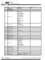
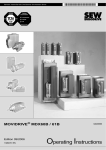
MOVIDRIVE® MDX60B/61B
Edition 03/2008
11696613 / EN
Operating Instructions
SEW-EURODRIVE – Driving the world
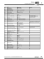
1 General Information ............................................................................................... 5
1.1 Structure of the safety notes .......................................................................... 5
1.2 Rights to claim under warranty....................................................................... 5
1.3 Exclusion of liability ........................................................................................ 5
2 Safety Notes ........................................................................................................... 6
2.1 General information ....................................................................................... 6
2.2 Target group .................................................................................................. 6
2.3 Designated use .............................................................................................. 6
2.4 Transportation, storage .................................................................................. 7
2.5 Installation ...................................................................................................... 7
2.6 Electrical connection ...................................................................................... 7
2.7 Safe disconnection......................................................................................... 8
2.8 Operation ....................................................................................................... 8
3 Unit Design ............................................................................................................. 9
3.1 Unit designation, nameplates and scope of delivery...................................... 9
3.2 Size 0 ........................................................................................................... 12
3.3 Size 1 ........................................................................................................... 13
3.4 Size 2S......................................................................................................... 14
3.5 Size 2 ........................................................................................................... 15
3.6 Size 3 ........................................................................................................... 16
3.7 Size 4 ........................................................................................................... 17
3.8 Size 5 ........................................................................................................... 18
3.9 Size 6 ........................................................................................................... 19
4 Installation ............................................................................................................ 20
4.1 Installation instructions for the basic unit ..................................................... 20
4.2 Removing/installing the keypad ................................................................... 27
4.3 Removing/installing the front cover .............................................................. 28
4.4 UL-compliant installation .............................................................................. 30
4.5 Shield clamps............................................................................................... 32
4.6 Touch guard power terminals...................................................................... 35
4.7 Wiring diagrams – basic unit ........................................................................ 38
4.8 Assignment of braking resistors, chokes and filters ..................................... 42
4.9 Connecting the system bus (SBus 1)........................................................... 48
4.10 Connecting the RS485 interface .................................................................. 49
4.11 Connecting the DWE11B/12B interface adapter.......................................... 50
4.12 Connecting UWS21B (RS232) interface adapter......................................... 52
4.13 Connecting the USB11A interface adapter .................................................. 53
4.14 Option combinations for MDX61B................................................................ 54
4.15 Installing and removing options cards.......................................................... 56
4.16 Connecting the encoder and resolver .......................................................... 58
4.17 Terminal description of the DEH11B option (HIPERFACE®) and connection .
60
4.18 DEH21B option connection and terminal description................................. 64
4.19 Connecting option DER11B (resolver) ......................................................... 66
4.20 Connecting an external encoder .................................................................. 69
4.21 Connecting an incremental encoder simulation ........................................... 72
4.22 Master/slave connection .............................................................................. 73
4.23 DIO11B – connection and terminal description............................................ 74
4.24 DFC11B – connection and terminal description.......................................... 77
Operating Instructions – MOVIDRIVE® MDX60B/61B Inverter
3
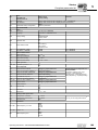
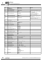
5 Startup................................................................................................................... 78
5.1 General startup instructions ......................................................................... 78
5.2 Preliminary work and resources................................................................... 80
5.3 Startup with DBG60B keypad ...................................................................... 81
5.4 Startup with PC and MOVITOOLS® ............................................................ 89
5.5 Starting the motor ........................................................................................ 91
5.6 Complete parameter list ............................................................................... 95
6 Operation ............................................................................................................ 106
6.1 Operating displays ..................................................................................... 106
6.2 Information messages................................................................................ 107
6.3 Functions of the DBG60B keypad.............................................................. 108
6.4 Memory card .............................................................................................. 111
7 Service ................................................................................................................ 113
7.1 Fault information ........................................................................................ 113
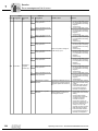
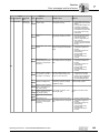
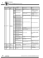
7.2 Error messages and list of errors ............................................................... 114
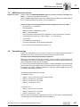
7.3 SEW Electronics Service ........................................................................... 127
7.4 Extended storage ....................................................................................... 127
7.5 Disposal ..................................................................................................... 128
8 Technical Data and Dimension Drawings ........................................................ 129
8.1 CE marking, UL approval and C-Tick......................................................... 129
8.2 General technical data ............................................................................... 130
8.3 MOVIDRIVE® MDX60/61B...-5_3 (AC 400/500 V units) ........................... 132
8.4 MOVIDRIVE® MDX61B...-2_3 (AC 230 V units) ....................................... 139
8.5 MOVIDRIVE® MDX60/61B electronics data.............................................. 143
8.6 MOVIDRIVE® MDX60B dimension drawings ............................................ 145
8.7 MOVIDRIVE® MDX61B dimension drawings ............................................ 147
8.8 Technical data for options DEH11B, DEH21B, DER11B and BW...-T/...-P 156
8.9 Technical data of DIO11B and DFC11B options........................................ 158
9 Index .................................................................................................................... 159
4
Operating Instructions – MOVIDRIVE® MDX60B/61B Inverter
General Information
Structure of the safety notes
1
General Information
1.1
Structure of the safety notes
1
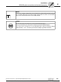
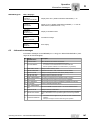
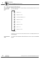
The safety notes in these operating instructions are structured as follows:
Symbol
SIGNAL WORD
Nature and source of hazard.
Possible consequence(s) if disregarded.
•
Symbol
Example:
Measure(s) to avoid the hazard.
Signal word
Meaning
Consequences if disregarded
HAZARD
Imminent hazard
Severe or fatal injuries
WARNING!
Possible hazardous situation
Severe or fatal injuries
CAUTION!
Possible hazardous situation
Minor injuries
STOP!
Possible damage to property
Damage to the drive system or its environment
NOTE
Useful information or tip.
Simplifies handling of the drive
system.
General hazard
Specific hazard,
e.g. electric shock
1.2
Rights to claim under warranty
A requirement of fault-free operation and fulfillment of any rights to claim under limited warranty is that you adhere to the information in the operating instructions. Read
the operating instructions before you start operating the unit!
Make sure that the operating instructions are available to persons responsible for the
system and its operation as well as to persons who work independently on the unit. You
must also ensure that the documentation is legible.
1.3
Exclusion of liability
You must comply with the information contained in these operating instructions
to ensure safe operation of the MOVIDRIVE® MDX60B/61B inverters and to
achieve the specified product characteristics and performance requirements.
SEW-EURODRIVE assumes no liability for injury to persons or damage to equipment or property resulting from non-observance of these operating instructions.
In such cases, any liability for defects is excluded.
Operating Instructions – MOVIDRIVE® MDX60B/61B Inverter
5
Safety Notes
General information
2
2
Safety Notes
The following basic safety notes are intended to prevent injury to persons and damage
to property. The operator must make sure that the basic safety notes are read and observed. Make sure that persons responsible for the system and its operation, as well as
persons who work independently on the unit, have read through the operating instructions carefully and understood them. If you are unclear about any of the information in
this documentation, or if you require further information, please contact
SEW-EURODRIVE.
2.1
General information
Never install damaged products or take them into operation. Submit a complaint to the
shipping company immediately in the event of damage.
During operation, inverters can have live, bare and movable or rotating parts as well as
hot surfaces, depending on their enclosure.
Removing covers without authorization, improper use as well as incorrect installation or
operation may result in severe injuries to persons or damage to property.
Consult the documentation for additional information.
2.2
Target group
Only qualified personnel are authorized to install, startup or service the units or correct
unit faults (observing IEC 60364 or CENELEC HD 384 or DIN VDE 0100 and IEC 60664
or DIN VDE 0110 as well as national accident prevention guidelines).
Qualified electricians in the context of these basic safety notes are persons familiar with
installation, assembly, startup and operation of the product who possess the required
qualifications.
All activity in the other areas of transportation, storage, operation, and disposal must be
carried out by persons who are appropriately trained.
2.3
Designated use
Inverters are components intended for installation in electrical systems or machines.
In case of installation in machines, startup of the inverters (i.e. start of designated operation) is prohibited until it is determined that the machine meets the requirements stipulated in the EC Directive 98 37 EC (machine guideline); observe EN 60204.
Startup (i.e. start of designated operation) is only permitted with adherence to the
EMC (89/336/EEC) guideline.
The inverters comply with the low voltage guideline 2006/95/EC. The harmonized standards of the EN 61800-5-1/DIN VDE T105 series in connection with
EN 60439-1/VDE 0660 part 500 and EN 60146/VDE 0558 are applied to these inverters.
Technical data and information on the connection requirements are provided on the
nameplate and in the documentation; these must be observed under all circumstances.
6
Operating Instructions – MOVIDRIVE® MDX60B/61B Inverter
Safety Notes
Transportation, storage
Safety functions
2
The MOVIDRIVE® MDX60B/61B inverters may not perform safety functions without
higher-level safety systems. Use higher-level safety systems to ensure protection of
equipment and personnel.
For safety applications, refer to the information in the following publications:
2.4
•
Safe Disconnection for MOVIDRIVE® MDX60B/61B – Conditions
•
Safe Disconnection for MOVIDRIVE® MDX60B/61B – Applications
Transportation, storage
You must observe the notes on transportation, storage and proper handling. Observe
the climatic conditions as stated in the section "General technical data."
2.5
Installation
The units must be installed and cooled according to the regulations and specifications
in the corresponding documentation.
Protect the inverters from excessive strain. Especially during transportation and handling, do not allow the components to be deformed or insulation spaces altered. Avoid
contact with electronic components and contacts.
Inverters contain components that can be damaged by electrostatic energy and improper handling. Prevent mechanical damage or destruction of electric components (may
pose health risk).
The following applications are prohibited unless the unit is explicitly designed for such
use:
2.6
•
Use in potentially explosive areas
•
Use in areas exposed to harmful oils, acids, gases, vapors, dust, radiation, etc.
•
Use in non-stationary applications that are subject to mechanical vibration and shock
loads in excess of the requirements in EN 61800-5-1.
Electrical connection
Observe the applicable national accident prevention guidelines when working on live inverters (e.g. BGV A3).
Perform electrical installation according to the pertinent regulations (e.g. line cross sections, fusing, protective conductor connection). Additional information is contained in the
documentation.
You will find notes on EMC-compliant installation, such as shielding, grounding, arrangement of filters and routing of lines, in the documentation of the inverters. Always
observe these notes even with inverters bearing the CE marking. The manufacturer of
the system or machine is responsible for maintaining the limits established by EMC legislation.
Preventive measures and protection devices must correspond to the regulations in force
(e.g. EN 60204 or EN 61800-5-1).
Required preventive measure: grounding the unit.
Operating Instructions – MOVIDRIVE® MDX60B/61B Inverter
7
Safety Notes
Safe disconnection
2
2.7
Safe disconnection
The unit meets all requirements for safe disconnection of power and electronic connections in accordance with EN 61800-5-1. All connected circuits must also satisfy the requirements for safe disconnection.
2.8
Operation
Systems with integrated inverters must be equipped with additional monitoring and protection devices, if necessary, according to the applicable safety guidelines, such as the
law governing technical equipment, accident prevention regulations, etc. Changes to the
inverter using the operating software are permitted.
Do not touch live components or power connections immediately after disconnecting the
inverters from the supply voltage because there may still be some charged capacitors.
Note the respective labels on the inverter.
Keep all covers and doors closed during operation.
The fact that the status LED and other display elements are no longer illuminated does
not indicate that the unit has been disconnected from the power supply and no longer
carries any voltage.
Mechanical blocking or internal safety functions of the unit can cause a motor standstill.
Eliminating the cause of the problem or performing a reset may result in the drive restarting automatically. If, for safety reasons, this is not permitted for the driven machine,
disconnect the unit from the mains before correcting the fault.
8
Operating Instructions – MOVIDRIVE® MDX60B/61B Inverter
Unit Design
Unit designation, nameplates and scope of delivery
3
Unit Design
3.1
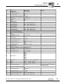
Unit designation, nameplates and scope of delivery
3
Example: Unit designation
MDX60 B 0011 - 5 A 3 - 4 00
Design
00 = Standard
0T = Application
XX = Special unit
Quadrants
4 = 4Q (with brake chopper)
Connection type
3 = 3-phase
Radio interference suppression on the line
side
B = Radio interference suppression C1
A = Radio interference suppression C2
0 = No radio interference suppression
Supply voltage
Recommended
motor power
5 = AC 380 ... 500 V
2 = AC 200 ... 230 V
0011 = 1.1 kW
Version B
Series
Example: System
nameplate size 0
60 = No options can be installed
61 = Options can be installed
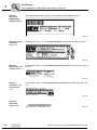
The system nameplate of MDX60B/61B.. size 0 is attached to the side of the unit.
52246AXX
Operating Instructions – MOVIDRIVE® MDX60B/61B Inverter
9
Unit Design
Unit designation, nameplates and scope of delivery
3
Example:
Nameplate
BW090-P52B
braking resistor
The BW090-P52B braking resistor is only available for MDX60B/61B size 0.
90
54522AXX
Example: System
nameplate
sizes 1 - 6
For MDX61B.. sizes 1 - 6, the system nameplate is attached to the side of the unit.
56493AXX
Example:
Nameplate power
section sizes 1 - 6
For MDX61B.. sizes 1-6, the nameplate of the power section is located at the side of
the unit.
56492AXX
Example:
Nameplate control unit sizes
1-6
For MDX61B.. sizes 1-6, the nameplate of the control unit is located at the side of the
unit.
56491AXX
Example:
Nameplate
option card
62882AXX
10
Operating Instructions – MOVIDRIVE® MDX60B/61B Inverter
Unit Design
Unit designation, nameplates and scope of delivery
Scope of delivery
Size 0
•
Connector housing for all signal terminals (X10 ... X17), connected
•
Connector housing for the power terminals (X1 ... X4), connected
•
Pluggable memory card, connected
•
1 set of shield clamps for power cable and signal cable, not installed. The set of
shield clamps comprises:
–
–
–
–
–
–
Sizes 1-6
•
2 shield clamps for power cable (2 contact clips each)
1 shield clamp for signal cable (1 contact clip) for MDX60B
1 shield clamp for signal cable (2 contact clips) for MDX61B
6 contact clips
6 screws for attaching the contact clips
3 screws for attaching the contact clips to the unit
1 set of shield clamps for signal cable, not installed. The set of shield clamps comprises:
–
–
–
–
Size 2S
3
1 shield clamp for signal cable (1 contact clip)
2 contact clips
2 screws for attaching the contact clips
1 screw for attaching the shield clamp to the unit
•
Only for size 6: Carrying bar and 2 split pins
•
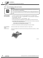
Accessories set, not installed. The accessories set (→ Following figure) comprises:
– 2 mounting feet [1] to be plugged into the heat sink
– 2 touch guards [2] to be fastened to terminals X4: -Uz/+Uz and X3:-R(8)/+R(9).
Degree of protection IP20 is achieved as soon as one of the following conditions is
fulfilled:
– The touch guard [2] mounted to X3 / X4 (→chapter "Touch guard")
– An adequate cable connected to X3 / X4
If neither of the two conditions is fulfilled, the degree of protection is IP10.
[1]
[2]
54587AXX
Operating Instructions – MOVIDRIVE® MDX60B/61B Inverter
11
Unit Design
Size 0
3
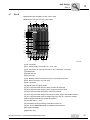
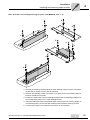
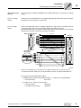
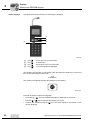
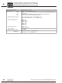
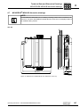
3.2
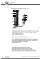
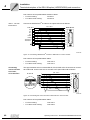
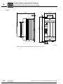
Size 0
MDX60/61B-5A3 (AC 400/500 V units): 0005 ... 0014
[1]
[15]
[2]
[3]
[14]
[13]
[12]
[11]
[6]
[10]
[16]
[17]
[9]
[4]
[20]
[18]
[19]
[8]
[7]
[5]
*
[6]
62710AXX
* View of the bottom of the unit
[1] Power shield clamp for mains connection and connection for DC link connection
[2] X4: Connection for DC link connection UZ– / UZ+ and PE connection, separable
[3] X1: Power supply connection L1, L2, L3 and PE connection, separable
[4] Only with MDX61B: Fieldbus slot
[5] Only with MDX61B: Encoder slot
[6] Shield clamp for signal cables MDX61B size 0
[7] X10: Signal terminal strip for binary outputs and TF/TH input
[8] X16: Signal terminal strip binary inputs and outputs
[9] X13: Signal terminal strip terminal strip for binary inputs and RS485 interface
[10] X11: Signal terminal strip for setpoint input AI1 and 10 V reference voltage
[11]X12: Signal terminal strip system bus (SBus)
[12] S11 DIP switch ... S14
[13] XT: Slot for DBG60B keypad or UWS21B serial interface
[14]7-segment display
[15]Memory card
[16] Threaded hole for grounding screw M4×8 or M4×10
[17] X17: Signal terminal strip for safety contacts for safe stop
[18] X2: Motor connection U, V, W and PE connection, separable
[19] X3: Braking resistor connection +R / –R and PE connection, separable
[20]Power shield clamp for motor connection and braking resistor connection
12
Operating Instructions – MOVIDRIVE® MDX60B/61B Inverter
Unit Design
Size 1
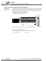
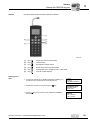
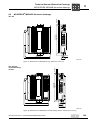
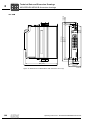
3.3
3
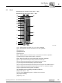
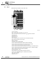
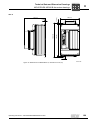
Size 1
MDX61B-5A3 (AC 400/500 V units): 0015 ... 0040
MDX61B-2A3 (AC 230 V units): 0015 ... 0037
[1]
[2]
[19]
[18]
[17]
[16]
[15]
[14]
[13]
[3]
[12]
[4]
[11]
[5]
[10]
[9]
[8]
[7]
[6]
62711AXX
[1] X1: Power supply connection 1/L1, 2/L2, 3/L3, separable
[2] X4: Connection for DC link connection –UZ +UZ, separable
[3] Fieldbus slot
[4] Expansion slot
[5] Encoder slot
[6] X3: Braking resistor connection 8/+R, 9/–R and PE connection, separable
[7] Shield clamp for signal cables and PE connection
[8] X2: Motor connection 4/U, 5/V, 6/W and PE connection, separable
[9] X17: Signal terminal strip for safety contacts for safe stop
[10] X10: Signal terminal strip for binary outputs and TF/TH input
[11] X16: Signal terminal strip binary inputs and outputs
[12] X13: Signal terminal strip terminal strip for binary inputs and RS485 interface
[13] X11: Signal terminal strip for setpoint input AI1 and 10 V reference voltage
[14]X12: Signal terminal strip system bus (SBus)
[15] Threaded hole for grounding screw M4×8 or M4×10
[16] S11 DIP switch ... S14
[17] XT: Slot for DBG60B keypad or UWS21B serial interface
[18]7-segment display
[19]Memory card
Operating Instructions – MOVIDRIVE® MDX60B/61B Inverter
13
Unit Design
Size 2S
3
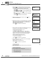
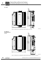
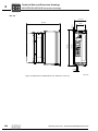
3.4
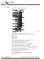
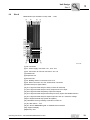
Size 2S
MDX61B-5A3 (AC 400/500 V units): 0055 / 0075
[1]
[2]
[3]
[19]
[18]
[17]
[16]
[15]
[14]
[4]
[13]
[12]
[5]
[6]
[11]
[10]
[9]
[7]
[8]
62712AXX
[1] X1: Power supply connection 1/L1, 2/L2, 3/L3
[2] X4: Connection for DC link connection –UZ +UZ and PE connection
[3] Memory card
[4] Fieldbus slot
[5] Expansion slot
[6] Encoder slot
[7] X3: Braking resistor connection 8/+R, 9/–R and PE connection
[8] Shield clamp for signal cables and PE connection
[9] X2: Motor connection 4/U, 5/V, 6/W
[10] X17: Signal terminal strip for safety contacts for safe stop
[11] X10: Signal terminal strip for binary outputs and TF/TH input
[12] X16: Signal terminal strip binary inputs and outputs
[13] X13: Signal terminal strip terminal strip for binary inputs and RS485 interface
[14] X11: Signal terminal strip for setpoint input AI1 and 10 V reference voltage
[15]X12: Signal terminal strip system bus (SBus)
[16] Threaded hole for grounding screw M4×8 or M4×10
[17] S11 DIP switch ... S14
[18] XT: Slot for DBG60B keypad or UWS21B serial interface
[19]7-segment display
14
Operating Instructions – MOVIDRIVE® MDX60B/61B Inverter
Unit Design
Size 2
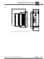
3.5
3
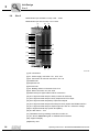
Size 2
MDX61B-5A3 (AC 400/500 V units): 0110
MDX61B-2A3 (AC 230 V units): 0055 / 0075
[1]
[2]
[19]
[18]
[17]
[16]
[15]
[14]
[13]
[3]
[12]
[4]
[11]
[5]
[10]
[9]
[8]
[6]
[7]
62713AXX
[1] X1: Power supply connection 1/L1, 2/L2, 3/L3
[2] X4: Connection for DC link connection –UZ +UZ and PE connection
[3] Fieldbus slot
[4] Expansion slot
[5] Encoder slot
[6] X3: Braking resistor connection 8/+R, 9/–R and PE connection
[7] Shield clamp for signal cables and PE connection
[8] X2: Motor connection 4/U, 5/V, 6/W
[9] X17: Signal terminal strip for safety contacts for safe stop
[10] X10: Signal terminal strip for binary outputs and TF/TH input
[11] X16: Signal terminal strip binary inputs and outputs
[12] X13: Signal terminal strip terminal strip for binary inputs and RS485 interface
[13] X11: Signal terminal strip for setpoint input AI1 and 10 V reference voltage
[14]X12: Signal terminal strip system bus (SBus)
[15] Threaded hole for grounding screw M4×8 or M4×10
[16] S11 DIP switch ... S14
[17] XT: Slot for DBG60B keypad or UWS21B serial interface
[18]7-segment display
[19]Memory card
Operating Instructions – MOVIDRIVE® MDX60B/61B Inverter
15
Unit Design
Size 3
3
3.6
Size 3
MDX61B-503 (AC 400/500 V units): 0150 ... 0300
MDX61B-203 (AC 230 V units): 0110 / 0150
[1]
[2]
[3]
[20]
[19]
[18]
[17]
[16]
[15]
[14]
[4]
[13]
[5]
[12]
[6]
[11]
[10]
[9]
[8]
[7]
62714AXX
[1] PE connections
[2] X1: Power supply connection 1/L1, 2/L2, 3/L3
[3] X4: Connection for DC link connection –UZ +UZ
[4] Fieldbus slot
[5] Expansion slot
[6] Encoder slot
[7] X3: Braking resistor connection 8/+R, 9/–R
[8] X2: Motor connection 4/U, 5/V, 6/W
[9] Shield clamp for signal cables and PE connection
[10] X17: Signal terminal strip for safety contacts for safe stop
[11] X10: Signal terminal strip for binary outputs and TF/TH input
[12] X16: Signal terminal strip binary inputs and outputs
[13] X13: Signal terminal strip terminal strip for binary inputs and RS485 interface
[14] X11: Signal terminal strip for setpoint input AI1 and 10 V reference voltage
[15]X12: Signal terminal strip system bus (SBus)
[16] S11 DIP switch ... S14
[17] Threaded hole for grounding screw M4×8 or M4×10
[17] XT: Slot for DBG60B keypad or UWS21B serial interface
[18]7-segment display
[19]Memory card
16
Operating Instructions – MOVIDRIVE® MDX60B/61B Inverter
Unit Design
Size 4
3.7
3
Size 4
MDX61B-503 (AC 400/500 V units): 0370 / 0450
MDX61B-203 (AC 230 V units): 0220 / 0300
[1]
[2]
[3]
[21]
[20]
[19]
[18]
[17]
[16]
[15]
[4]
[14]
[13]
[5]
[12]
[6]
[11]
[10]
[9]
[8]
[7]
62715AXX
[1] PE connection
[2] X1: Power supply connection 1/L1, 2/L2, 3/L3
[3] X4: Connection for DC link connection –UZ +UZ and PE connection
[4] Fieldbus slot
[5] Expansion slot
[6] Encoder slot
[7] X3: Braking resistor connection 8/+R, 9/–R and PE connection
[8] X2: Motor connection 4/U, 5/V, 6/W
[9] PE connection
[10] Shield clamp for signal cables
[11] X17: Signal terminal strip for safety contacts for safe stop
[12] X10: Signal terminal strip for binary outputs and TF/TH input
[13] X16: Signal terminal strip binary inputs and outputs
[14] X13: Signal terminal strip terminal strip for binary inputs and RS485 interface
[15] X11: Signal terminal strip for setpoint input AI1 and 10 V reference voltage
[16]X12: Signal terminal strip system bus (SBus)
[17] S11 DIP switch ... S14
[18] Threaded hole for grounding screw M4×8 or M4×10
[19] XT: Slot for DBG60B keypad or UWS21B serial interface
[20]7-segment display
[21]Memory card
Operating Instructions – MOVIDRIVE® MDX60B/61B Inverter
17
Unit Design
Size 5
3
3.8
Size 5
MDX61B-503 (AC 400/500 V units): 0550 / 0750
[1]
[2]
[3]
[21]
[20]
[19]
[18]
[17]
[16]
[15]
[4]
[14]
[5]
[13]
[6]
[12]
[11]
[10]
[9]
[8]
[7]
62716AXX
[1] PE connection
[2] X1: Power supply connection 1/L1, 2/L2, 3/L3
[3] X4: Connection for DC link connection –UZ +UZ and PE connection
[4] Fieldbus slot
[5] Expansion slot
[6] Encoder slot
[7] X3: Braking resistor connection 8/+R, 9/–R and PE connection
[8] X2: Motor connection 4/U, 5/V, 6/W
[9] PE connection
[10] Shield clamp for signal cables
[11] X17: Signal terminal strip for safety contacts for safe stop
[12] X10: Signal terminal strip for binary outputs and TF/TH input
[13] X16: Signal terminal strip binary inputs and outputs
[14] X13: Signal terminal strip terminal strip for binary inputs and RS485 interface
[15] X11: Signal terminal strip for setpoint input AI1 and 10 V reference voltage
[16]X12: Signal terminal strip system bus (SBus)
[17] S11 DIP switch ... S14
[18] Threaded hole for grounding screw M4×8 or M4×10
[19] XT: Slot for DBG60B keypad or UWS21B serial interface
[20]7-segment display
[21]Memory card
18
Operating Instructions – MOVIDRIVE® MDX60B/61B Inverter
Unit Design
Size 6
3.9
3
Size 6
MDX61B-503 (AC 400/500 V units): 0900 ... 1320
[1]
[3]
[2]
[1]
[20]
[19]
[18]
[17]
[16]
[15]
[14]
[4]
[13]
[5]
[12]
[11]
[6]
[10]
[9]
[1]
[8]
[7]
[1]
62717AXX
[1] PE connection
[2] X1: Power supply connection 1/L1, 2/L2, 3/L3
[3] X4: Connection for DC link connection –UZ +UZ
[4] Fieldbus slot
[5] Expansion slot
[6] Encoder slot
[7] X3: Braking resistor connection 8/+R, 9/–R
[8] X2: Motor connection 4/U, 5/V, 6/W and PE connection
[9] Shield clamp for signal cables
[10] X17: Signal terminal strip for safety contacts for safe stop
[11] X10: Signal terminal strip for binary outputs and TF/TH input
[12] X16: Signal terminal strip binary inputs and outputs
[13] X13: Signal terminal strip terminal strip for binary inputs and RS485 interface
[14] X11: Signal terminal strip for setpoint input AI1 and 10 V reference voltage
[15]X12: Signal terminal strip system bus (SBus)
[16] Threaded hole for grounding screw M4×8 or M4×10
[17] S11 DIP switch ... S14
[18] XT: Slot for DBG60B keypad or UWS21B serial interface
[19]7-segment display
[20]Memory card
Operating Instructions – MOVIDRIVE® MDX60B/61B Inverter
19
Installation
Installation instructions for the basic unit
4
4
Installation
4.1
Installation instructions for the basic unit
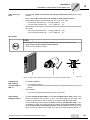
Assembly notes
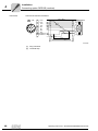
for size 6
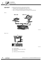
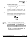
The MOVIDRIVE® units of size 6 (0900 ... 1320) are equipped with a fixed lifting eye [1].
Use a crane and lifting eye [1] to install the unit.
HAZARD
Suspended load.
Danger of fatal injury if the load falls.
•
Do not stand under the suspended load.
•
Secure the danger zone.
If a crane is not available, you can push a carrying bar [2] through the rear panel [4] to
facilitate installation (included in the delivery scope of size 6). Secure the carrying bar
[2] against axial displacement using the split pin [3].
[3]
[2]
[1]
[4]
[3]
Figure 1: Installing MOVIDRIVE® size 6 with fixed lifting eye and carrying bar
59892AXX
[1] Fixed lifting eye
[2] Carrying bar (included in the delivery of size 6)
[3] 2 split pins (included in the delivery scope of size 6)
[4] Rear panel
20
Operating Instructions – MOVIDRIVE® MDX60B/61B Inverter
Installation
Installation instructions for the basic unit
Tightening
torques
•
Only use original connection elements. Note the permitted tightening torques of
MOVIDRIVE® power terminals.
–
–
–
–
–
Minimum clearance and Mounting position
4
Sizes 0, 1 and 2S
Size 2
Size 3
Sizes 4 and 5
Size 6
→
→
→
→
→
0.6 Nm (5 lb in)
1.5 Nm (13 lb in)
3.5 Nm (31 lb in)
14.0 Nm (120 lb in)
20.0 Nm (180 lb in)
•
The permitted tightening torque of the signal terminals is 0.6 Nm (5 lb.in).
•
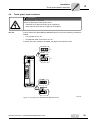
Leave at least 100 mm clearance above and below the unit for optimum cooling.
Make sure air circulation in the clearance is not impaired by cables or other installation equipment. With sizes 4, 5 and 6, do not install any components which are sensitive to high temperatures within 300 mm (12 in) of the top of the unit.
•
Ensure unobstructed cooling air supply and make sure that air heated by other units
cannot be drawn in or reused.
•
There is no need for clearance at the sides of the unit. You may line up the units directly next to each other.
•
Only install the units vertically. Do not install them horizontally, tilted or upside down
(→ following figure, applies to all sizes).
100 mm
(4 in)
100 mm
(4 in)
Figure 2: Minimum clearance and mounting position of the units
Separate cable
ducts
•
60030AXX
Route power cables and signal cables in separate cable ducts.
Operating Instructions – MOVIDRIVE® MDX60B/61B Inverter
21
Installation
Installation instructions for the basic unit
4
Fuses and earthleakage circuit
breaker
•
Install the fuses at the beginning of the supply system lead after the supply bus
junction (→ Wiring diagram for basic unit, power section and brake).
•
SEW-EURODRIVE recommends that you do not use earth-leakage circuit breakers.
However, if an earth-leakage circuit breaker is stipulated for direct or indirect protection against contact, observe the following note in accordance with EN 61800-5-1:
WARNING!
Incorrect earth-leakage circuit breaker installed.
Severe or fatal injuries.
MOVIDRIVE® can cause direct current in the protective earth. In cases where an earthleakage circuit breaker is used for protection against direct or indirect contact, only
install a type B earth-leakage circuit breaker on the power supply end of the
MOVIDRIVE® unit.
Mains and brake
contactors
•
Only use contactors in utilization category AC-3 (IEC 60947-4-1) as mains and
brake contactors.
NOTES
PE connection
(→EN 61800-5-1)
•
Only use the mains contactor K11 (→ section. "Wiring diagram – basic unit") to
switch the inverter on and off. Do not use it for jog mode. Use the commands
"Enable/Stop", "CW/Stop" or "CCW/Stop" for jog mode.
•
Observe a minimum switch-off time of 10 s for the input contactor K11.
Earth-leakage currents ≥ 3.5 mA may occur during normal operation. To meet the
requirements of EN 61800-5-1 observe the following points:
•
Supply system cable < 10 mm2 (AWG 7):
Route a second PE conductor with the cable cross section of the power supply
line in parallel to the protective earth via separate terminals or use a copper protective earth conductor with a cable cross section of 10 mm2 (AWG 7).
•
Supply system cable 10 mm2 ... 16 mm2 (AWG 7 ... AWG 6):
Route a copper protective earth conductor with the cable cross section of the
supply system cable.
•
Supply system cable 16 mm2 ... 35 mm2 (AWG 6 ... AWG 2):
Route a copper protective earth conductor with a cable cross section of
16 mm2.
•
Supply system cable > 35 mm2 (AWG 2):
Route a copper protective earth conductor with half the cable cross section of
the supply system cable.
IT systems
22
•
MOVIDRIVE® B is designed for operation on TN and TT systems with a directly
grounded star point. Operation on voltage supply systems with a non-grounded star
point is permitted In this case, SEW-EURODRIVE recommends using earthleakage monitors with pulse-code measurement for voltage supply systems with
a non-grounded star point (IT systems). Using such devices prevents the earthleakage monitor from mis-tripping due to the ground capacitance of the inverter. No
EMC limits have been specified for interference emission in voltage supply
systems without grounded star point (IT systems).
Operating Instructions – MOVIDRIVE® MDX60B/61B Inverter
Installation
Installation instructions for the basic unit
Cable cross sections
4
•
Supply cable: Cable cross section according to rated input current ISupply at rated load.
•
Motor cable: Cable cross section according to rated output current IN.
•
Signal cables of basic unit (terminals X10, X11, X12, X13, X16):
– One core per terminal 0.20 ... 2.5 mm2 (AWG 24 ... 13)
– Two cores per terminal 0.25 ... 1 mm2 (AWG 23 ... 17)
•
Signal cables of terminal X17 and DIO11B terminal expansion board (terminals X20,
X21, X22):
– One core per terminal 0.08 ... 1.5 mm2 (AWG 28 ... 16)
– Two cores per terminal 0.25 ... 1 mm2 (AWG 23 ... 17)
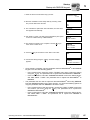
Unit output
STOP!
MOVIDRIVE® B can suffer irreparable damage if you connect capacitive loads.
•
Only connect ohmic/inductive loads (motors).
•
Never connect capacitive loads.
Figure 3: Only connect ohmic/inductive loads; do not connect capacitive loads
Installing the
BW...braking
resistors/ BW..-T /
BW...-P
•
60031AXX
Permitted installation:
– on horizontal surfaces
– on vertical surfaces with brackets at the bottom and perforated sheets at top and
bottom
•
Not permitted:
– on vertical surfaces with brackets at the top, right or left
AConnecting
braking resistors
•
Use two closely twisted cables or a 2-core shielded power cable. Cable cross
section according to trip current IF of F16. The rated voltage of the cable must
amount to at least U0/U = 300 V / 500 V (in accordance with DIN VDE 0298).
•
Protect the braking resistor (except for BW90-P52B) using a bimetallic relay (→ wiring diagram for basic unit, power section and brake). Set the trip current according
to the technical data of the braking resistor. SEW-EURODRIVE recommends using an overcurrent relay from trip class 10 or 10A in accordance with EN 60947-4-1.
Operating Instructions – MOVIDRIVE® MDX60B/61B Inverter
23
Installation
Installation instructions for the basic unit
4
Operating braking resistors
•
For braking resistors of the BW...-T / BW...-P series, the integrated temperature
switch/overcurrent relay can be connected using a shielded 2-core cable as an
alternative to a bimetallic relay.
•
Flat-type braking resistors have internal thermal overload protection (fuse which
cannot be replaced). Install the flat-type braking resistors together with the appropriate touch guard.
•
The connection leads to the braking resistors carry a high pulsed DC voltage during
rated operation.
WARNING!
The surfaces of the braking resistors get very hot when the braking resistors are loaded
with Prated.
Risk of burns and fire.
Binary inputs /
binary outputs
EMC-compliant
installation
•
Choose a suitable installation location. Braking resistors are usually mounted on top
of the control cabinet.
•
Do not touch the braking resistors.
•
The binary inputs are electrically isolated by optocouplers.
•
The binary outputs are short-circuit proof and protected against external voltage to DC 30 V. External voltages > DC 30 V can cause irreparable damage to binary outputs.
•
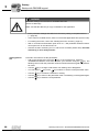
All cables except for the supply system lead must be shielded. As an alternative to
the shielding, the option HD.. (output choke) can be used for the motor cable to
achieve the emitted interference limit values. .
•
When using shielded motor cables, e.g. prefabricated motor cables from
SEW-EURODRIVE, you must keep the unshielded conductors between the
shield and connection terminal of the inverter as short as possible.
•
Apply the shield by the shortest possible route and make sure it is grounded
over a wide area at both ends. Ground one end of the shield via a suppression capacitor (220 nF / 50 V) to avoid ground loops. If using double-shielded cables, ground
the outer shield on the inverter end and the inner shield on the other end.
Figure 4: Correct shield connection using metal clamp (shield clamp) or cable gland
24
60028AXX
Operating Instructions – MOVIDRIVE® MDX60B/61B Inverter
Installation
Installation instructions for the basic unit
•
You can also use grounded sheet-metal ducts or metal pipes to shield the cables. Route the power and signal cables separately.
•
Ground the inverter and all additional units to ensure high-frequency compatibility (wide area, metal-on-metal contact between the unit housing and ground, e.g.
unpainted control cabinet mounting panel).
4
NOTES
NF.. line filter
•
MOVIDRIVE® B is a product with restricted availability in accordance with EN
61800-3. It may cause EMC interference. In this case, the operator may need to implement appropriate measures.
•
For detailed information on EMC compliant installation, refer to the publication
"Electromagnetic Compatibility in Drive Engineering" from SEW-EURODRIVE.
•
The NF.. line filter option can be used to maintain the class C1 limit for MOVIDRIVE®
MDX60B/61B units size 0 to 5.
•
Do not switch between the line filter and MOVIDRIVE® MDX60B/61B.
•
Install the line filter close to the inverter but outside the minimum clearance for
cooling.
•
Keep the length of the cable between the line filter and inverter to an absolute
minimum, and never more than 400 mm. Unshielded, twisted cables are sufficient.
Also use unshielded cables as the supply system lead.
•
SEW-EURODRIVE recommends taking one of the following EMC measures on the
motor side to maintain class C1 and C2 limits:
– Shielded motor cable
– HD... output choke option
– HF.. output filter option (in operating modes VFC and U/f)
Interference emission category
Compliance with category C2 according to EN 61800-3 has been tested on a specified
test setup. SEW-EURODRIVE can provide detailed information on request.
WARNING!
This product can cause high-frequency interferences in residential areas which can require measures for interference suppression.
Operating Instructions – MOVIDRIVE® MDX60B/61B Inverter
25
4
Installation
Installation instructions for the basic unit
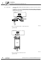
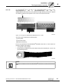
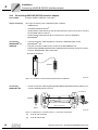
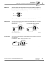
HD... output choke
•
Install the output choke close to the inverter but outside the minimum clearance
for cooling.
•
For HD001 ... HD003: Route all three phases of the motor cable [1] through the
output choke. To achieve a higher filter effect, do not route the PE conductor
through the output choke!
MOVIDRIVE®
X2:
U V
W
n=5
PE U V W
HD001HD003
[1]
Figure 5: Connecting the HD001 ... HD003 output choke
62878AXX
[1] Motor cable
MOVIDRIVE® B
U
X2:
V
W
V
W
U
HD004
U1
V1
W1
M
~
Figure 6: Connecting the HD004 output choke
62879AXX
[1] Motor cable
26
Operating Instructions – MOVIDRIVE® MDX60B/61B Inverter
Installation
Removing/installing the keypad
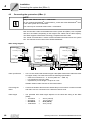
4.2
4
Removing/installing the keypad
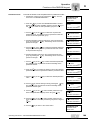
Removing the
keypad
Proceed as follows:
1.
2.
3.
STOP
RUN
DEL
OK
STOP
RUN
DEL
OK
2.
60032AXX
Figure 7: Removing the keypad
1. Unplug the connection cable from the XT slot.
2. Carefully push the keypad downwards until it comes off the upper fixture on the front
cover.
3. Remove the keypad forward (not to the side!).
Installing the
keypad
Proceed as follows:
2.
3.
STOP
RUN
DEL
OK
1.
STOP
RUN
DEL
OK
Figure 8: Installing the keypad
60033AXX
1. Place the underside of the keypad onto the lower fixture of the front cover.
2. Push the keypad into the upper fixture of the front cover.
3. Plug the connecting cable into the XT slot.
Operating Instructions – MOVIDRIVE® MDX60B/61B Inverter
27
Installation
Removing/installing the front cover
4
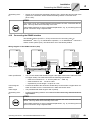
4.3
Removing/installing the front cover
Removing the
front cover
Proceed as follows to remove the front cover:
1.
2.
Figure 9: Removing the front cover
60034AXX
1. If a keypad is installed, remove it first (→ page 27).
2. Press the grooved clip on top of the front cover.
3. Keep the clip pressed down to remove the front cover.
28
Operating Instructions – MOVIDRIVE® MDX60B/61B Inverter
Installation
Removing/installing the front cover
Installing the
front cover
4
Proceed as follows to install the front cover:
2.
3.
BG0
1.
BG1 -6
1.
Figure 10: Installing the front cover
60035AXX
1. Insert the underside of the front cover into the support.
2. Keep the grooved clip on top of the front cover pressed down.
3. Push the front cover onto the unit.
Operating Instructions – MOVIDRIVE® MDX60B/61B Inverter
29
Installation
UL-compliant installation
4
4.4
UL-compliant installation
Observe the following notes for UL-compliant installation:
•
Only use copper cables with the following rated thermal values as connection cables:
•
MOVIDRIVE® MDX60B/61B0005 ... 0300:
Rated thermal value 60 °C / 75 °C
•
MOVIDRIVE® MDX61B0370 ... 1320:
Rated thermal value 75 °C
•
Permitted tightening torques for MOVIDRIVE® power terminals:
–
–
–
–
–
•
AC 400/500 V
units
30
Size 0,1 and 2S
Size 2
Size 3
Sizes 4 and 5
Size 6
→
→
→
→
→
0.6 Nm (5 lb in)
1.5 Nm (13 lb in)
3.5 Nm (31 lb in)
14.0 Nm (120 lb in)
20.0 Nm (180 lb in)
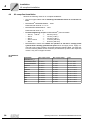
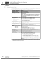
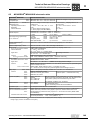
MOVIDRIVE® inverters are suitable for operation in TN and TT voltage power
systems with a directly grounded star point which can supply a max. supply current and a max. supply voltage in accordance with the following table. The fuses listed in the following tables are the maximum permitted back-up fuse of the respective
inverter. Only use UL-approved fuses.
MOVIDRIVE®
MDX60B/61B...5_3
Max. supply current
0005/0008/0011/0014
AC 5000 A
AC 500 V
AC 15 A / 600 V
0015/0022/0030/0040
AC 10000 A
AC 500 V
AC 35 A / 600 V
0055/0075
AC 5000 A
AC 500 V
AC 60 A / 600 V
0110
AC 5000 A
AC 500 V
AC 110 A / 600 V
0150/0220
AC 5000 A
AC 500 V
AC 175 A / 600 V
0300
AC 5000 A
AC 500 V
AC 225 A / 600 V
0370/0450
AC 10000 A
AC 500 V
AC 350 A / 600 V
0550/0750
AC 10000 A
AC 500 V
AC 500 A / 600 V
0900
AC 10000 A
AC 500 V
AC 250 A / 600 V
1100
AC 10000 A
AC 500 V
AC 300 A / 600 V
1320
AC 10000 A
AC 500 V
AC 400 A / 600 V
Max. supply voltage
Fuses
Operating Instructions – MOVIDRIVE® MDX60B/61B Inverter
Installation
UL-compliant installation
4
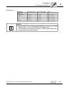
AC 230 V units
MOVIDRIVE®
MDX61B...2_3
Max. supply current
Max. supply voltage
Fuses
0015/0022/0037
AC 5000 A
AC 240 V
AC 30 A / 250 V
0055/0075
AC 5000 A
AC 240 V
AC 110 A / 250 V
0110
AC 5000 A
AC 240 V
AC 175 A / 250 V
0150
AC 5000 A
AC 240 V
AC 225 A / 250 V
0220/0300
AC 10000 A
AC 240 V
AC 350 A / 250 V
NOTES
•
Use only tested units with a limited output voltage (Umax = DC 30 V) and limited
output current (I ≤ 8 A) as an external DC 24 V voltage source.
•
UL certification does not apply to operation in voltage supply systems with a
non-grounded star point (IT systems).
Operating Instructions – MOVIDRIVE® MDX60B/61B Inverter
31
Installation
Shield clamps
4
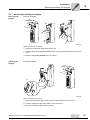
4.5
Shield clamps
Shield clamp for
power section,
size 0
A set of shield clamps is supplied as standard for the power section of MOVIDRIVE®
MDX60B/61B size 0. The shield clamps are not yet installed.
Install the shield clamps for the power section as follows:
•
Secure the contact clips to the shield plates.
•
Secure the shield clamps to the top and the bottom of the unit.
[1]
[2]
[3]
[4]
Figure 11: Securing the shield clamp of the power section (size 0)
32
[1]
Contact clips
[2]
Retaining screws for contact clip
[3]
Shield plate
[4]
Retaining screw for shield clamp
62718AXX
Operating Instructions – MOVIDRIVE® MDX60B/61B Inverter
Installation
Shield clamps
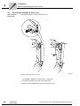
Shield clamp for
power section,
size 1
4
A shield clamp is supplied as standard for the power section with MOVIDRIVE®
MDX61B size 1. Install this shield clamp on the power section together with the unit’s
retaining screws.
[1]
[2]
Figure 12: Securing the shield clamp on the power section (size 1)
[1]
Shield clamp for
power section,
size 2S and 2
Power section shield clamp
[2]
60019AXX
PE connection (댷)
A shield clamp for the power section is supplied as standard with two retaining screws
with MOVIDRIVE® MDX61B sizes 2S and 2. Install these shield clamp using the two retaining screws.
[1]
[2]
Figure 13: Securing the shield clamp on the power section (figure shows size 2)
[1]
Power section shield clamp
[2]
60020AXX
PE connection (댷)
The shield clamps for the power section provide you with a very convenient way of installing the shield for the motor and brake cables. Apply the shield and PE conductor as
shown in the figures.
Shield clamp for
power section,
sizes 3 to 6
No shield clamps for the power section are supplied with MOVIDRIVE® MDX61B sizes
3 to 6. Use commercially available shield clamps for installing the shielding of motor and
brake cables. Apply the shield as closely as possible to the inverter.
Operating Instructions – MOVIDRIVE® MDX60B/61B Inverter
33
Installation
Shield clamps
4
Shield clamp for
signal cables
Install the shield clamp for the signal cable as follows:
•
If installed, remove the keypad and the front cover.
•
Size 0: Attach the shield clamp on the bottom of the unit.
•
Sizes 1 to 6: Attach the shield clamp on the bottom of the control unit.
Size 0
MDX 60B
MDX 61B
[1]
[2]
[4]
[1]
[2]
[4]
[3]
[3]
62722AXX
Sizes 1 to 6
[1]
[2]
[3]
[4]
62719AXX
34
[1]
Contact clip(s)
[2]
Retaining screw(s) for contact clips
[3]
Shield plate
[4]
Retaining screw for shield clamp
Operating Instructions – MOVIDRIVE® MDX60B/61B Inverter
Installation
Touch guard power terminals
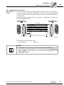
4.6
4
Touch guard power terminals
HAZARD
Uncovered power connections.
Severe or fatal injuries from electric shock.
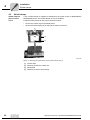
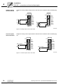
Size 2S
•
Install the touch guard according to the regulations.
•
Never start the unit if the touch guard is not installed.
IP20 is achieved for MOVIDRIVE® MDX61B size 2S if one of the following conditions is
fulfilled:
•
Touch guard on X3 / X4.
•
An adequate cable connected to X3 / X4
If neither of the two conditions is fulfilled, the degree of protection is IP10.
IP10
X4
-UZ +UZ PE
IP20
X4
-UZ +UZ PE
1
2
3
4
5
6
7
8
9
+/-
0
.
IP10
X3
8/+R 9/-R PE
IP20
X3
8/+R 9/-R PE
Figure 14: Touch guard for MOVIDRIVE® MDX61B size 2S
Operating Instructions – MOVIDRIVE® MDX60B/61B Inverter
54408AXX
35
Installation
Touch guard power terminals
4
Sizes 4 and 5
IP20 is achieved for MOVIDRIVE® MDX61B sizes 4 and 5 (AC 500 V units:
MDX61B0370/0450/0550/0750; AC 230 V units: MDX61B0220/0300), as soon as one
of the following conditions is fulfilled:
•
Cables with shrink tubing and a cable cross section of ≥ 35 mm2 (AWG2) are connected to X1, X2, X3, X4. The additional DLB11B touch guard does not have to be
installed.
•
Cables with shrink tubing and a cable cross section of < 35 mm2 (AWG2) are connected to X1, X2, X3, X4. The DLB11B touch guard must be installed properly (see
section 'Installing the DLB11B touch guard').
•
The DLB11B must be connected to power terminals that are not connected. The
DLB11B does not have to be connected to the PE terminals.
If neither of the conditions is fulfilled, the degree of protection is IP10. The DLB11B (12
pieces included in the scope of delivery) is available via the
part number 0823 111 7 .
Installing the
DLB11B touch
guard
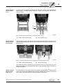
Proceed as follows when installing the DLB11B touch guard:
•
Figure I: Power terminal with connected power cable with a cable cross section of
< 35 mm2 (AWG2):
Remove the plastic saddle [1] and push the DLB11B touch guard [3] on the respective stud [2] of the power terminal. Make sure that the cable output is straight. Install
the cover for the power terminals.
•
Figure II: Power terminal without connected power cable:
Push the DLB11B touch guard [1] on the respective stud [2]. Install the cover for the
power terminals.
II
I
[2]
[1]
[1]
[3]
[2]
[3]
90°
63208AXX
63206AXX
[1] Plastic saddle
[1] Touch guard
[2] Terminal stud
[2] Terminal stud
[3] Touch guard properly installed
[3] Touch guard properly installed
For additional information on the X1, X2, X3 and X4 power terminals, refer to chapter
"Technical Data".
36
Operating Instructions – MOVIDRIVE® MDX60B/61B Inverter
Installation
Touch guard power terminals
Sizes 4-6
4
For MOVIDRIVE® size 4 (AC 500 V units: MDX61B0370/0450; AC 230 V units:
MDX61B0220/0300),
size
5
(MDX61B0550/0750)
and
size
6
(MDX61B0900/1100/1320), two touch guards with eight retaining screws are supplied
as standard. Install the touch guard on both covers of the power terminals.
[2]
[1]
[3]
Figure 15: Touch guard for MOVIDRIVE® MDX61B sizes 4, 5 and 6
06624AXX
The touch guard comprises the following parts:
[1] Cover plate
[2] Connection plate
[3] Screen (only size 5)
IP10 is only achieved for the MOVIDRIVE® MDX61B units sizes 4, 5 and 6 when the
following conditions are fulfilled:
•
Touch guard is fully installed
•
Shrink tubing is installed on the power cables of all power terminals (X1, X2, X3, X4)
(see following picture)
62925AXX
NOTE
If the above conditions are not met, MOVIDRIVE® units sizes 4, 5 and 6 have enclosure
IP00.
Operating Instructions – MOVIDRIVE® MDX60B/61B Inverter
37
Installation
Wiring diagrams – basic unit
4
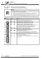
4.7
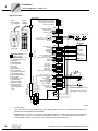
Wiring diagrams – basic unit
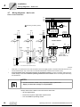
Power section and brake
L1
L2
L3
PE
F11/F12/F13
K11
(AC-3)
Grounding conductor (shield)
L1 L2
UAC
UAC
UAC
F14/F15
F14/F15
K11
(AC-3)
K11
(AC-3)
L3
NF... line filter option
L1' L2' L3'
F14/F15
DC link
connection*
L1 L2 L3
-UZ +UZ
X1:
X4:
Power section
K11
(AC-3)
X2:
DBØØ
DBØØ
DGND
K12
(AC-3)
U
DBØØ
V
X3:
PE
+R -R
W
K12
(AC-3)
DGND
1
BMK 2
3
4
13
14
15
PE
1
BG 2
3
BGE 4
5
Brake connector** CT/CV/DT/DV/D:
Cut-off in the AC and
DC circuit
→ Section "Braking
resistor BW... /
BW..-T / BW...-P"
DGND
weiß
rot
blau
1
BG 2
3
BGE 4
5
weiß
rot
blau
M
3-phase
CT/CV/DT/DV/D:
Cut-off in the AC
- circuit
CT/CV, CM71 ... 112: Cut-off in the AC and DC circuit
62875ADE
*
With sizes 1, 2 and 2S, there is no PE connection next to the supply system connection terminals and motor connection terminals (X1, X2). In this case, use the PE terminal next to the DC link connection (X4).
**
You must adhere to the connection sequence of the brake connector. Incorrect connection will cause irreparable damage to the brake. Read the operating instructions for the motors when connecting the brake using
the terminal box.
NOTES
•
Connect the brake rectifier using a separate supply system lead.
•
Supply via the motor voltage is not permitted!
Always switch off the brake on the DC and AC sides with:
– all hoist applications,
– Drives that require a rapid brake response time
– CFC and SERVO operating modes
38
Operating Instructions – MOVIDRIVE® MDX60B/61B Inverter
Installation
Wiring diagrams – basic unit
Brake rectifier in
the control cabinet
4
Install the connection cables between the brake rectifier and the brake separately from
other power cables when installing the brake rectifier in the control cabinet. Joint installation is only permitted with shielded power cables.
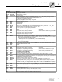
Braking resistor BW... / BW...-...-T /BW...-...-P
Power section
X3:
Power section
Power section
X3:
X3:
PE
PE
PE
+R -R
+R -R
+R -R
F16
Wirkt
auf K11
BW...-...-P
F16
98
4
BW...-...-T
95
97
T2
RB1
affects
K11
affects
K11
96
T1
6
BW...
RB2
When the internal temperature
switch trips, K11 must be opened
and DIØØ"/Controller inhibit"
must receive a "0" signal. The
resistor circuit must not be
interrupted!
When the signal contact F16 trips,
K11 must be opened and DIØØ"/Controller
inhibit" must receive a "0" signal. The resistor
circuit must not be interrupted!
When the external bimetal relay
(F16) trips, K11 must be opened and
DIØØ "/Controller inhibit" must
receive a "0" signal . The resistor
circuit must not be interrupted!
62876ADE
Overload protection
Braking resistor type
Design specified
Internal temperature switch
(..T)
External bimetallic relay
(F16)
Required
BW...
-
-
BW...-...-T
-
One of the two options (internal temperature switch / external
bimetallic relay) is required.
BW...-003 / BW...-005
Adequate
-
Permitted
BW090-P52B
Adequate
-
-
Operating Instructions – MOVIDRIVE® MDX60B/61B Inverter
39
Installation
Wiring diagrams – basic unit
4
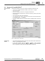
Signal terminals
Control unit
Switchover I signal <-> U signal *
System bus terminating resistor
XT: 9.6 kBaud <-> 57.6 kBaud*
Frequency input active
Option
keypad
DBG60B
XT
S 11
S 12
S 13
S 14
ON OFF*
X12:
RS485
System bus reference
System bus high
System bus low
DGND
SC11
SC12
1
2
3
R11
DE L
DC+10 V
+
n1 (0...10 V*; +/-10 V)
DC 0...20 mA; 4 ... 20 mA
Reference pot. analog signals
DC-10 V
OK
RS232
Typ:
UWS21B
Sach-Nr 1 820 456 2
X11:
7-segment display
DC-10V...+10V DC0(4)...20 mA
I
U
Higher-level
controller
Binary
input
DIØØ
DIØ1
DIØ2
DIØ3
DIØ4
DIØ5
DCOM* *
VO2 4
DGND
ST11
ST12
1
2
3
4
5
6
7
8
9
10
11
Binary
outputs
Reference
binary outputs
DGND
X16:
DIØ6
DIØ7
DOØ3
DOØ4
DOØ5
DGND
1
2
3
4
5
6
X10:
K12
(AC-3)
24V
Connect external DC 24 V supply
depending on the options used
(MOVIDRIVE® electronics data)
1
2
3
4
X17:
1
TF1
2
DGND
3
DBØØ
DOØ1-C 4
DOØ1-NO 5
DOØ1-NC 6
7
DOØ2
8
VO24
VI24
9
DGND 10
Shield plate or
shield clamp
Reference potential binary signals
DC+24 V output
Ref. DC+24 V input for safe stop
DC+24 V input
for safe stop
Input TF-/TH-/KTY+
Reference pot. binary signals
/brake
Relay contact
Ready*
Relay NO contact
Relay NC contact
/Fault*
DC+24 V output
DC+24 V input
Reference pot.
binary signals
DGND
VO24
SOV24
SVI24
.
/Controller inhibit
CW/stop*
CCW/stop*
Enable/stop*
n11/n21*
n12/n22*
Ref. X13:DIØØ...DIØ5
DC+24 V output
Reference pot. binary signals
RS485 +
RS485 No function*
No function*
IPOS output*
IPOS output*
IPOS output*
Reference pot. binary signals
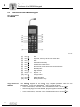
Option slots
Only with MDX61B
0
1
2
3
4
5
6
7
8
9
A
c
d
E
F
H
t
U
1
2
3
4
5
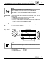
X13:
Socket
sub D 9-pin
7-segment display
Operating status
Inverter not ready
Controller inhibit active
No enable
Standstill current
VFC operation
n-control
M-control
Hold control
Factory setting
Limit switch contacted
Technology option
IPOS reference travel
Flying start
Calibrate encoder
Fault display
Manual operation
Waiting for data
Safe stop active
IPOS program
Runnning (flashing
dot)
REF1
AI 11
AI12
AGND
REF2
X11:AI11/AI12
Option
serial interface
e. g. UWS21B
59219ADE
*
Factory setting
**
If the binary inputs are connected to the DC 24 V voltage supply X13:8 "VO24", install a jumper between X13:7
(DCOM) and X13:9 (DGND) on MOVIDRIVE®.
DGND (X10, X12, X13, X16, X17) is electrically isolated as standard. The electrical isolation can be disabled by
means of a M4 x 8 or M4 x 10 grounding screw (tightening torque 1.4 ... 1,61.6 Nm). The grounding screw
(threaded hole ? chapter →Unit Design→) is not included in the scope of delivery.
40
Operating Instructions – MOVIDRIVE® MDX60B/61B Inverter
Installation
Wiring diagrams – basic unit
4
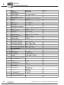
Description of terminal functions of the basic unit (power section and control unit)
Terminal
X1:1/2/3
X2:4/5/6
X3:8/9
X4:
Function
L1/L2/L3 (PE)
U/V/W (PE)
+R/-R (PE)
+UZ/-UZ (PE)
Power supply connection
Motor connection
Braking resistor connection
DC link connection
Change I-signal DC(0(4)...20 mA) ↔ V-signal DC(-10 V...0...10 V, 0...10 V), factory setting to V signal.
Switching system bus terminating resistor on/off; factory setting: OFF.
Set baud rate for the RS485 interface XT.
Either 9.6 or 57.6 kBaud, factory setting: 75.6 kBaud.
Switch frequency input on or off, factory setting: switched off.
S11
S12:
S13:
S14:
X12:1
X12:2
X12:3
DGND
SC11
SC12
Reference potential system bus
System bus high
System bus low
X11:1
X11:2/3
X11:4
X11:5
REF1
AI11/12
AGND
REF2
DC+10 V (max. DC 3 mA) for setpoint potentiometer
Setpoint input n1 (differential input or input with AGND reference potential), signal form → P11_ / S11
Reference potential for analog signals (REF1, REF2, AI.., AO..)
DC–10 V (max. DC 3 mA) for setpoint potentiometer
X13:1
X13:2
X13:3
X13:4
X13:5
X13:6
DIØØ
DIØ1
DIØ2
DIØ3
DIØ4
DIØ5
Binary input 1, with fixed assignment"/Controller
inhibit"
Binary input 2, factory setting to "CW/stop"
Binary input 3, factory setting to "CCW/stop"
Binary input 4, factory setting to "Enable/Stop"
Binary input 5, factory setting to "n11/n21"
Binary input 6, factory setting to "n11/n22"
X13:7
DCOM
Reference for binary inputs X13:1 to X13:6 (DIØØ ... DIØ5) and X16:1/X16:2 (DIØ6 ... DIØ7)
• Switching binary inputs with DC+24 V external voltage: Connection X13:7 (DCOM) must be connected
to the reference potential of the external voltage.
– Without jumper X13:7-X13:9 (DCOM-DGND) → Isolated binary inputs
– With jumper X13:7-X13:9 (DCOM-DGND) → Non-isolated binary inputs
•
•
•
The binary inputs are electrically isolated by
optocouplers.
Selection options for binary inputs 2 to 6 (DIØ1
... DIØ5) → Parameter menu P60_
The binary inputs must be switched with DC+24 V from X13:8 or X10:8 (VO24) → Jumper required
X13:7-X13:9 (DCOM-DGND).
X13:8
X13:9
X13:10
X13:11
VO24
DGND
ST11
ST12
Auxiliary supply output DC+24 V (max. load X13:8 and X10:8 = 400 mA) for external command switches
Reference potential for binary signals
RS485+ (baud rate has a fixed setting of 9.6 kBaud)
RS485-
X16:1
X16:2
X16:3
X16:4
X16:5
DIØ6
DIØ7
DOØ3
DOØ4
DOØ5
X16:6
DGND
Binary input 7, factory setting "no function"
Binary input 8, factory setting "no function"
Binary output 3, factory setting "IPOS output"
Binary output 4, factory setting "IPOS output"
Binary output 5, factory setting "IPOS output"
Do not connect external voltage to binary outputs
X16:3 (DOØ3) and X16:5 (DOØ5)!
Reference potential for binary signals
X10:1
X10:2
X10:3
TF1
DGND
DBØØ
X10:4
X10:5
X10:6
X10:7
DOØ1-C
DOØ1-NO
DOØ1-NC
DOØ2
X10:8
X10:9
X10:10
VO24
VI24
DGND
Auxiliary supply output DC+24 V (max. load X13:8 and X10:8 = 400 mA) for external command switches
Input DC+24 V voltage supply (backup voltage depending on options, unit diagnosis when supply system
off)
Reference potential for binary signals
X17:1
X17:2
X17:3
X17:4
DGND
VO24
SOV24
SVI24
Reference potential for X17:3
Auxiliary supply voltage DC+24 V, only to supply X17:4 on the same unit
Reference potential for DC+24 V input "Safe stop" (safety contact)
DC+24 V input "Safe stop" (safety contact)
XT
•
•
•
The binary inputs are electrically isolated by
optocouplers.
Selection options for binary inputs 7 and 8
(DIØ6/DIØ7) → Parameter menu P60_
Selection option for binary inputs 3 to 5
(DOØ3...DOØ5) → Parameter menu P62_
KTY+/TF-/TH connection (connect to X10:2 via TF/TH), factory setting to "No response" (→ P835)
Reference potential for binary signals / KTY–
Binary output DBØØ has fixed assignment "/Brake", load capacity max DC 150 mA (short-circuit proof, protected against external voltage to DC 30 V)
Shared contact binary output 1, factory setting "Ready"
Normally open contact binary output 1, max. load of relay contacts DC 30 V and DC 0.8 A
NC contact binary output 1
Binary output DBØ2, factory setting "/Fault", max. load capacity DC 50 mA (short-circuit proof, protected
against external voltage to DC 30 V). Selection options for binary outputs 1 and 2 (DOØ1 and DOØ2) →
Parameter menu P62_. Do not apply external voltage to binary outputs X10:3 (DBØØ) and X10:7 (DOØ2).
Only service interface. Option slot: DBG60B / UWS21B / USB11A
Operating Instructions – MOVIDRIVE® MDX60B/61B Inverter
41
Installation
Assignment of braking resistors, chokes and filters
4
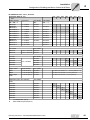
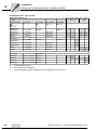
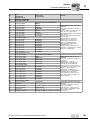
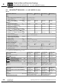
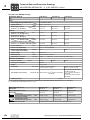
4.8
Assignment of braking resistors, chokes and filters
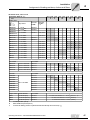
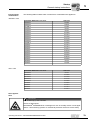
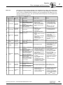
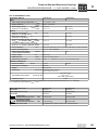
AC 400/500 V units, size 0
MOVIDRIVE® MDX60/61B...-5A3
0005
0008
Size
Braking resistors
BW... /
BW..-..-T
Trip current
Part number
BW...
BW090-P52B1)
-
824 563 0
BW072-003
IF = 0.6 ARMS
826 058 3
BW072-005
IF = 1.0 ARMS
826 060 5
BW168/BW168-T
IF = 3.4 ARMS
820 604 X
1820 133 4
BW100-006
BW100-006-T
IF = 2.4 ARMS
821 701 7
1820 419 8
Σ Imains = AC 20 A
826 012 5
Line chokes
ND020-013
0014
Part number
BW...-...-T
Part number
Line filter
NF009-503
0011
0
Part number
Umax = AC 550 V
827 412 6
Output chokes
Inside diameter
Part number
HD001
d = 50 mm (2 in)
813 325 5
for cable cross sections 1.5 ... 16 mm2 (AWG 16 ...
6)
HD002
d = 23 mm (0.91 in)
813 557 6
for cable cross sections ≤ 1.5 mm2 (AWG 16)
Output filter (only in VFC operating mode)
Part number
HF008-503
826,029 X
A
HF015-503
826 030 3
B
HF022-503
826 031 1
A
B
1) Internal thermal overload protection, no bimetallic relay required.
42
A
In rated operation (100 %)
B
With variable torque load (125 %)
Operating Instructions – MOVIDRIVE® MDX60B/61B Inverter
Installation
Assignment of braking resistors, chokes and filters
4
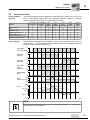
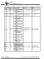
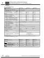
AC 400/500 V units, size 1, 2S and 2
MOVIDRIVE® MDX61B...-5A3
0015
0022
Size
0030
0040
Braking resistors
BW... / BW..-..-T
Trip current
Part number
BW...
BW100-005
IF = 0.8 ARMS
826 269 1
BW100-006/
BW100-006-T
IF = 2.4 ARMS
821 701 7
BW168/BW168-T
IF = 3.4 ARMS
820 604 X
1820 133 4
BW268/BW268-T
IF = 4.2 ARMS
820 715 1
1820 417 1
BW147/BW147-T
IF = 5 ARMS
820 713 5
1820 134 2
BW247/BW247-T
IF = 6.5 ARMS
820 714 3
1820 084 2
BW347/BW347-T
IF = 9.2 ARMS
820 798 4
1820 135 0
BW039-012/
BW039-012-T
IF = 5.5 ARMS
821 689 4
1820 136 9
BW039-026-T
IF = 8.1 ARMS
1820 415 5
BW039-050-T
IF = 11.3 ARMS
1820 137 7
Line chokes
Σ Imains = AC 20 A
826 012 5
ND045-013
Σ Imains = AC 45 A
826 013 3
0110
2
Part number
BW...-...-T
1820 419 8
Line filter
Part number
NF009-503
827 412 6
A
827,116 X
B
NF014-503
0075
2S
Part number
ND020-013
NF018-503
0055
1
Umax = AC 550 V
NF035-503
A
B
827 413 4
827 128 3
Output chokes
Inside diameter
Part number
HD001
d = 50 mm (2 in)
813 325 5
for cable cross sections 1.5 ... 16 mm2 (AWG 16 ... 6)
HD002
d = 23 mm (0.91 in)
813 557 6
for cable cross sections ≤ 1.5 mm2 (AWG 16)
HD003 output
choke
d = 88 mm (3.5 in)
813 558 4
for cable cross sections > 16 mm2 (AWG 6)
Output filter (only in VFC operating
mode)
Part number
HF015-503
826 030 3
A
HF022-503
826 031 1
B
HF030-503
826,032 X
HF040-503
826 311 6
HF055-503
826 312 4
HF075-503
826 313 2
HF023-403
825 784 1
HF033-403
825,785 X
A
In rated operation (100 %)
B
With variable torque load (125 %)
Operating Instructions – MOVIDRIVE® MDX60B/61B Inverter
A
B
A
B
A
B
A
B
A
B
A
B
43
Installation
Assignment of braking resistors, chokes and filters
4
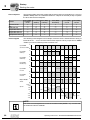
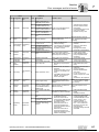
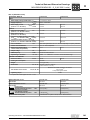
AC 400/500 V units, sizes 3 and 4
MOVIDRIVE® MDX61B...-503
0150
Size
Part number
BW...
BW018-015/
BW018-015-P
IF = 9.1 ARMS
821 684 3
BW018-035-T
IF = 13.9 ARMS
BW018-075-T
IF = 20.4 ARMS
0370
1820 413 9
0450
4
Part number
BW...-...-P
C
C
1820 138 5
C
C
1820 139 3
C
C
1 820 416 3
BW915-T
IF = 32.6 ARMS
IF = 14.4ARMS
BW012-050-T
IF = 20.4 ARMS
1820 140 7
BW012-100-T
IF = 28.8 ARMS
1820 141 5
BW106-T
IF = 47.4 ARMS
1820 083 4
BW206-T
IF = 54.7 ARMS
1820 412 0
Line chokes
44
Part number
BW...-...-T
BW012-025/
BW012-025-P
ND045-013
0300
3
Trip current
Braking resistors
BW... /
BW...-...-T
BW...-...-P
0220
821 680 0
1 820 414 7
Part number
Σ Imains = AC 45 A
826 013 3
A
826 014 1
B
ND085-013
Σ Imains = AC 85 A
ND150-013
Σ Imains = AC 150 A 825 548 2
ND300-0053
Σ Imains = AC 300 A 827 721 4
A
B
A
In rated operation (100 %)
B
With variable torque load (125 %)
C
Connect two braking resistors in parallel and set twice the trip current on F16 (2 × IF)
Operating Instructions – MOVIDRIVE® MDX60B/61B Inverter
Installation
Assignment of braking resistors, chokes and filters
4
AC 400/500 V units, sizes 5 and 6
MOVIDRIVE® MDX61B...-503
0550
Size
0750
0900
5
1320
6
Trip current
Part number
BW...
BW018-015/
BW018-015-P
IF = 9.1 ARMS
821 684 3
BW018-035-T
IF = 13.9 ARMS
1820 138 5
BW018-075-T
IF = 20.4 ARMS
1820 139 3
BW915-T
IF = 32.6 ARMS
1820 413 9
BW012-025/
BW012-025-P
IF = 14.4 ARMS
BW012-050-T
IF = 20.4 ARMS
1820 140 7
BW012-100-T
IF = 28.8 ARMS
1820 141 5
BW106-T
IF = 47.7 ARMS
1820 083 4
C
C
C
BW206-T
IF = 54.7 ARMS
1820 412 0
C
C
C
Braking
resistors
BW... /
BW...-...-T
BW...-...-P
Line chokes
Part number
BW...-...-T
1100
Part number
BW...-...-P
1 820 416 3
821 680 0
1 820 414 7
Part number
ND045-013
Σ Imains = AC 45 A
826 013 3
ND085-013
Σ Imains = AC 85 A
826 014 1
ND150-013
Σ Imains = AC 150 A
825 548 2
ND300-0053
Σ Imains = AC 300 A
827 721 4
A
In rated operation (100 %)
B
With variable torque load (125 %)
C
Connect two braking resistors in parallel and set twice the trip current on F16 (2 × IF)
Operating Instructions – MOVIDRIVE® MDX60B/61B Inverter
45
Installation
Assignment of braking resistors, chokes and filters
4
AC 400/500 V units, sizes 3 to 6
MOVIDRIVE® MDX61B...-503
0150
Size
Part number
NF035-503
827 128 3
A
NF048-503
827 117 8
B
NF063-503
827 414 2
NF085-503
Umax = AC 550 V
0370
0450
0550
4
0750
5
0900
1100
1320
6
A
B
A
B
827 415 0
A
B
827 416 9
A
B
NF150-503
827 417 7
NF210-503
827 418 5
A
NF300-503
827 419 3
B
Output chokes
Inside diameter
Part number
HD001
d = 50 mm
813 325 5
for cable cross sections 1.5...16 mm2 (AWG
16...6)
HD003 output
choke
d = 88 mm
813 558 4
for cable cross sections > 16 mm2 (AWG 6)
HD004
Connection
with M12 bolt
816 885 7
Output filter (only in VFC operating
mode)
46
0300
3
Line filter
NF115-503
0220
Part number
HF033-403
825,785 X
A
B/D
HF047-403
825 786 8
B
A
HF450-503
826 948 3
A/D
B
A
In rated operation (100 %)
B
With variable torque load (125 %)
D
Connect two output filters in parallel
E
In rated operation (100 %): one output filter
With variable torque load (125 %): two output filters in parallel
E
D
D
Operating Instructions – MOVIDRIVE® MDX60B/61B Inverter
Installation
Assignment of braking resistors, chokes and filters
4
AC 230 V units, sizes 1 to 4
MOVIDRIVE® MDX61B...-2_3
0015
Size
0022
0037
0055
1
0075
0110
2
0150
0220
3
0300
4
Braking resistors
BW...-.../
BW...-...-T
BW...-...-P
Trip current
Part number BW...
BW039-003
IF = 2.7 ARMS
821 687 8
BW039-006
IF = 3.9 ARMS
821 688 6
BW039-012
BW039-012-T
IF = 5.5 ARMS
821 689 4
BW039-026-T
IF = 8.1 ARMS
BW027-006
IF = 4.7 ARMS
822 422 6
BW027-012
IF = 6.6 ARMS
822 423 4
BW018-015-T
IF = 9.1 ARMS
1 820 416 3
C
C
C
C
BW018-035-T
IF = 13.9 ARMS
1 820 138 5
C
C
C
C
BW018-075-T
IF = 20.4 ARMS
1 820 139 3
C
C
C
C
BW915-T
IF = 32.6 ARMS
1 820 413 9
C
C
C
C
Part number BW......-T
1 820 136 9
1 820 415 5
BW012-025-P
IF = 14.4 ARMS
1 820 414 7
BW012-050-T
IF = 20.4 ARMS
1 820 140 7
BW012-100-T
IF = 28.8 ARMS
1 820 141 5
BW106-T
IF = 47.4 ARMS
1 820 083 4
C
C
BW206-T
IF = 54.7 ARMS
1 820 412 0
C
C
Line chokes
Part number
ND020-013
Σ Imains = AC 20 A
826 012 5
A
ND045-013
Σ Imains = AC 45 A
826 013 3
B
ND085-013
Σ Imains = AC 85 A
826 014 1
ND150-013
Σ Imains = AC 150 A
825 548 2
B
Part number
NF009-503
827 412 6
A
NF014-503
827,116 X
B
NF018-503
827 413 4
NF035-503
Umax = AC 550 V
A
B
Line filter
NF048-503
A
A
B
827 128 3
827 117 8
A
B
NF063-503
827 414 2
NF085-503
827 415 0
A
NF115-503
827 416 9
B
Output chokes
Inside diameter
Part number
HD001
d = 50 mm (2 in)
813 325 5
for cable cross sections 1.5 ... 16 mm2 (AWG 16 ... 6)
HD002
d = 23 mm (0.91 in)
813 557 6
for cable cross sections ≤ 1.5 mm2 (AWG 16)
HD003
d = 88 mm (3.5 in)
813 558 4
for cable cross sections > 16 mm2 (AWG 6)
A
In rated operation (100 %)
B
With variable torque load (125 %)
C
Connect two braking resistors in parallel and set twice the trip current on F16 (2 × IF)
Operating Instructions – MOVIDRIVE® MDX60B/61B Inverter
47
Installation
Connecting the system bus (SBus 1)
4
4.9
Connecting the system bus (SBus 1)
NOTE
Only if P884 "SBus baud rate" = 1000 kbaud:
Do not combine MOVIDRIVE® compact MCH4_A units with other MOVIDRIVE® units
in the same system bus combination.
The units may be combined at baud rates ≠ 1000 kbaud.
Max. 64 CAN bus nodes can be addressed via the system bus (SBus). Use a repeater
after 20 or 30 stations, depending on the length of the cables and the cable capacity.
The SBus supports transmission technology compliant with ISO 11898.
The "Serial Communication" manual contains detailed information about the system
bus. This manual can be ordered from SEW-EURODRIVE.
SBus wiring diagram
Control unit
S 11
S 12
S 13
S 14
Systembus
Terminating resistor
Control unit
ON OFF
Systembus
Ref.
Systembus High
Systembus Low
Control unit
1
2
3
Systembus
Ref.
Systembus High
Systembus Low
ON OFF
X12:
DGND
SC11
SC12
S 11
S 12
S 13
S 14
Systembus
Terminating resistor
ON OFF
X12:
DGND
SC11
SC12
S 11
S 12
S 13
S 14
Systembus
Terminating resistor
1
2
3
Systembus
Ref.
Systembus High
Systembus Low
X12:
DGND
SC11
SC12
1
2
3
54534AEN
Cable specification
•
Use a 4-core twisted and shielded copper cable (data transmission cable with braided copper shield). The cable must meet the following specifications:
– Cable cross section 0.25 ... 0.75 mm2 (AWG 23 ... AWG 19)
– Line resistance 120 Ω at 1 MHz
– Capacitance per unit length ≤ 40 pF/m at 1 kHz
Suitable cables include CAN bus or DeviceNet cables.
Connecting the
shield
•
Connect the shield to the electronics shield clamp on the inverter or master controller
and make sure it is connected over a wide area at both ends.
Cable length
•
The permitted total cable length depends on the baud rate setting of the SBus
(P884):
–
–
–
–
48
125 kbaud
250 kbaud
500 kBaud
1000 kbaud
→
→
→
→
320 m (1050 ft)
160 m (525 ft)
80 m (260 ft)
40 m (130 ft)
Operating Instructions – MOVIDRIVE® MDX60B/61B Inverter
Installation
Connecting the RS485 interface
Terminating resistor
•
4
Switch on the system bus terminating resistor (S12 = ON) at the start and end of the
system bus connection. Switch off the terminating resistor on the other units
(S12 = OFF).
STOP!
There must not be any potential displacement between the units connected with the
SBus. This may affect the functionality of the units.
Take suitable measures to avoid a potential displacement, e.g. by connecting the unit
ground connectors using a separate lead.
4.10
Connecting the RS485 interface
The RS485 interface (X13:ST11, ST12) can be used for connecting max. 32
MOVIDRIVE® units, e.g. for master/slave operation, or 31 MOVIDRIVE® units and a
master control system (PLC). The baud rate is set to 9.6 baud by default.
Wiring diagram of the RS485 interface (X13)
X13:
RS485+
RS485-
X13:
X13:
DIØØ 1
DIØ1 2
DIØ2 3
DIØ3 4
DIØ4 5
DIØ5 6
DCOM 7
VO24 8
DGND 9
ST11 10
ST12 11
RS485+
RS485-
DIØØ 1
DIØ1 2
DIØ2 3
DIØ3 4
DIØ4 5
DIØ5 6
DCOM 7
VO24 8
DGND 9
ST11 10
ST12 11
RS485+
RS485-
DIØØ 1
DIØ1 2
DIØ2 3
DIØ3 4
DIØ4 5
DIØ5 6
DCOM 7
VO24 8
DGND 9
ST11 10
ST12 11
54535AXX
Cable specification
•
Use a 4-core twisted and shielded copper cable (data transmission cable with braided copper shield). The cable must meet the following specifications:
– Cable cross section 0.25 ... 0.75 mm2 (AWG 23 ... AWG 19)
– Cable resistance 100 ... 150 Ω at 1 MHz
– Capacitance per unit length ≤ 40 pF/m at 1 kHz
Connecting the
shield
•
Connect the shield to the electronics shield clamp on the inverter or higher-level controller and make sure it is connected over a wide area at both ends.
Cable length
•
The permitted total cable length is 200 m (660 ft).
Terminating resistor
•
Dynamic terminating resistors are installed. Do not connect any external terminating resistors.
STOP!
There must not be any potential displacement between the units connected via the
RS485. This may affect the functionality of the units.
Take suitable measures to avoid a potential displacement, e.g. by connecting the unit
ground connectors using a separate lead.
Operating Instructions – MOVIDRIVE® MDX60B/61B Inverter
49
Installation
Connecting the DWE11B/12B interface adapter
4
4.11
Connecting the DWE11B/12B interface adapter
Part number and
description
•
DWE11B, part number 188 187 6
The interface adapter DWE11B (HTL→TTL) in the form of an adapter cable is used
to connect single-ended HTL encoders to theen DEH11B/DEH21B option. Only
the A, B and C tracks are connected. The interface adapter is suitable for all HTL encoders that were operated on MOVIDRIVE® A, MDV and MCV and can be connected
without any rewiring effort.
[A]
[C]
[B]
58748AXX
[A] 5 x 2 x 0,25 mm2 (AWG 23) / length 1000 mm (39.37 in) / max. cable length inverter - encoder: 100 m (328 ft)
[B] DC 24 V connection for HTL encoder; 1 x 0.5 mm2 (AWG 20) / length 250 mm
(9.84 in)
50
Signal
Terminal of 9-pin sub D socket [C] (encoder end)
A
1
B
2
C
3
UB
9
GND
5
Operating Instructions – MOVIDRIVE® MDX60B/61B Inverter
Installation
Connecting the DWE11B/12B interface adapter
•
4
DWE12B, part number 188 180 9
The DWE12B interface adapter (HTL→TTL) in the form of an adapter cable is used
to connect push-pull HTL encoders to the DEH11B/DEH21B options. In addition
to the A, B and C track, you will also have to connect the negated tracks (A, B, C).
SEW-EURODRIVE recommends using this interface adapter for any new system.
[A]
[C]
[B]
58748XX
[A] 4 x 2 x 0.25 mm2 (AWG 23) / length 1000 mm (39.37 in) / max. cable length
inverter - encoder: 200 m (656 ft)
[B] DC 24 V connection for HTL encoder; 1 x 0.5 mm2 (AWG 20) / length 250 mm
(9.84 in)
Signal
Terminal of 9-pin sub D socket [C] (encoder end)
A
1
A
6
B
2
B
7
C
3
C
8
UB
9
GND
5
Operating Instructions – MOVIDRIVE® MDX60B/61B Inverter
51
Installation
Connecting UWS21B (RS232) interface adapter
4
4.12
Connecting UWS21B (RS232) interface adapter
Part number
Interface adapter UWS21B: 1 820 456 2
Scope of delivery
The scope of delivery for the UWS21B option includes:
Connecting
MOVIDRIVE® to
UWS21B
•
UWS21B unit
•
CD-ROM with MOVITOOLS®
•
Serial interface cable with 9-pin sub D socket and 9-pin sub D connector to connect
the UWS21B option to the PC.
•
Serial interface cable with two RJ10 connectors to connect UWS21B to
MOVIDRIVE®.
•
Use the connection cable supplied to connect the UWS21B option to the
MOVIDRIVE® unit.
•
Plug the connection cable into the XT slot of the MOVIDRIVE® unit.
•
Note that the DBG60B keypad and the UWS21B serial interface cannot be connected to the MOVIDRIVE® at the same time.
MOVIDRIVE® MDX60/61B
UWS21B
59193AXX
Figure 16: Connection cable between MOVIDRIVE® and UWS21B
Connecting
UWS21B to PC
•
Use the connection cable supplied (shielded RS232 standard interface cable) to connect the UWS21B option to the PC.
PC COM 1-4
UWS21B
5
GND
5
3
2
TxD
3
2
RxD
max. 5 m (16.5 ft)
RS232
[1]
[2]
Figure 17: UWS21B-PC connection cable (1:1 connection assignment)
52
[1]
9-pin D-sub connector
[2]
9-pin D-sub socket
59194AXX
Operating Instructions – MOVIDRIVE® MDX60B/61B Inverter
Installation
Connecting the USB11A interface adapter
4.13
4
Connecting the USB11A interface adapter
Part number
Interface adapter USB11A: 824 831 1
Scope of delivery
•
The scope of delivery for the USB11A includes:
–
–
–
–
Connecting
MOVIDRIVE®USB11A - PC
USB11A interface adapter
USB connection cable PC - USB11A (type USB A-B)
Connection cable for MOVIDRIVE® MDX60B/61B - USB11A (cable RJ10-RJ10)
CD-ROM with drivers and MOVITOOLS®
•
The USB11A interface adapter supports USB 1.1 and USB 2.0.
•
Use the connection cable [1] (RJ10 - RJ10) supplied to connect the USB11A option
to the MOVIDRIVE® unit.
•
Plug the connection cable [1] into the XT slot of MOVIDRIVE® MDX60B/61B and into
the RS485 slot of the USB11A.
•
Note that the DBG60B keypad and the USB11A interface adapter cannot be connected to the MOVIDRIVE® at the same time.
•
Use the USB connection cable [2] (type USB A-B) to connect the USB11A to the PC.
MOVIDRIVE® MDX60/61B
PC COM 1-4
[1]
[2]
USB11A
Figure 18: Connection cable for MOVIDRIVE® MDX60B/61B - USB11A
Installation
Operation with
MOVITOOLS®
54532AXX
•
Connect the USB11A to a PC and MOVIDRIVE® MDX60B/61B using the connection
cables supplied.
•
Insert the enclosed CD into the CD drive of your PC and install the driver. The first
free COM port on the PC will be assigned to the USB11A interface adapter.
•
After installation, the PC recognizes the USB11A interface converter after approximately 5 to 10 s.
•
Start MOVITOOLS®.
NOTE
If the connection between the PC and USB11A is interrupted, you will have to restart
MOVITOOLS®.
Operating Instructions – MOVIDRIVE® MDX60B/61B Inverter
53
Installation
Option combinations for MDX61B
4
4.14
Option combinations for MDX61B
Arrangement of
the option slots
Size 0 (0005 ... 0014)
Sizes 1 ... 6 (0015 ... 1320)
[2]
[1]
[3]
62725AXX
54
[1]
Encoder slot for encoder options
[2]
Fieldbus slot for communication options
[3]
Expansion slot for communication options (only sizes 1 to 6)
Operating Instructions – MOVIDRIVE® MDX60B/61B Inverter
Installation
Option combinations for MDX61B
Option card combinations for
MDX61B
4
The option cards are different sizes and can only be installed in the matching option
slots. The following list shows the possible combinations of option cards for MOVIDRIVE® MDX61B.
MOVIDRIVE® MDX61B
Option
card
Designation
Encoder slot
Size 0 - size 6
DEH11B
Encoder input incr. / Hiperface®
X
DEH21B
Encoder input absolute encoder
X
DER11B
Encoder input resolver / Hiperface®
X
Fieldbus slot
Size 0 - size 6
DFP21B
Fieldbus interface Profibus
X
DFI11B
Fieldbus interface Interbus
X
DFI21B
Fieldbus interface Interbus LWL
X
DFD11B
DeviceNet fieldbus interface
X
DFC11B
Fieldbus interface CAN/CANopen
X
DFE11B
DFE12B
DFE13B
Fieldbus interface Ethernet
X
DFE32B
PROFINET IO fieldbus interface
X
DFE33B
EtherNet/IP fieldbus interface
X
DFE24B
EtherCAT fieldbus interface
X
DFS11B
Profibus fieldbus interface with
PROFIsafe (safe stop)
X
DFS12B
Profibus fieldbus interface with
PROFIsafe
X
DFS21B
PROFINET IO fieldbus Interface with
PROFIsafe (Safe Stop)
X
DCS21B/
31B
Safety monitor
DIO11B
I/O expansion
DRS11B
Phase-synchronous operation
Expansion slot
Size 1 - size 6
X
X
X1)
X
DIP11B
SSI encoder interface
DHP11B
User-programmable MOVI-PLC®
basic controller
X
X
DHE41B
User-programmable MOVI-PLC®
advanced controller
X
DHF41B
User-programmable MOVI-PLC®
advanced controller
X
DHR41B
User-programmable MOVI-PLC®
advanced controller
X
DHP11B
+ OST11B
DHP11B + OST11B (RS485 interface,
only in combination with DHP11B)
OST11B
DHP11B
X1)
DHP11B +
OST11B2)
1) When fieldbus slot is not available
2) When encoder slot is not available
Operating Instructions – MOVIDRIVE® MDX60B/61B Inverter
55
Installation
Installing and removing options cards
4
4.15
Installing and removing options cards
NOTES
Before you begin
•
For MOVIDRIVE® MDX61B size 0, only SEW-EURODRIVE is authorized to install
or remove option cards.
•
You can install or remove the option cards yourself for MOVIDRIVE® MDX61B sizes
1 to 6.
Read the following notes before installing or removing an option card:
STOP!
Electrostatic charge.
Damage to electronic components.
56
•
Disconnect the inverter from the power. Switch off the DC 24 V and the supply voltage.
•
Take appropriate measures to protect the option card from electrostatic charge (use
discharge strap, conductive shoes, etc.) before touching it.
•
Before installing the option card, remove the keypad (→ section "Removing/installing the keypad") and the front cover (→ section "Removing/installing the front
cover").
•
After having installed the option card, replace the keypad (→ Sec. "Removing/installing the keypad") and the front cover (→ section "Removing/installing the front
cover").
•
Keep the option card in its original packaging until immediately before you are ready
to install it.
•
Hold the option card by its edges only. Do not touch any components.
Operating Instructions – MOVIDRIVE® MDX60B/61B Inverter
Installation
Installing and removing options cards
4
Basic procedure for installing/removing an option card (MDX61B, sizes 1 - 6)
2.
1.
2.
1.
3.
3.
3.
4.
4.
60039AXX
1. Remove the retaining screws holding the card retaining bracket. Pull the card retaining bracket out evenly from the slot (do not twist).
2. Remove the retaining screws of the black cover plate on the card retaining bracket.
Remove the black cover plate.
3. Position the option card onto the retaining bracket so that the retaining screws fit into
the corresponding bores on the card retaining bracket.
4. Insert the retaining bracket with installed option card into the slot, pressing slightly so
it is seated properly. Secure the card retaining bracket with the retaining screws.
5. To remove the option card, follow the instructions in reverse order.
Operating Instructions – MOVIDRIVE® MDX60B/61B Inverter
57
Installation
Connecting the encoder and resolver
4
4.16
Connecting the encoder and resolver
NOTES
General installation information
•
The wiring diagrams do now show the view onto the cable end. They show the connection to the motor or MOVIDRIVE®.
•
The core colors specified in the wiring diagrams are in accordance with the IEC 757
color code and correspond to the core colors used in the prefabricated cables from
SEW.
•
The sub D connectors shown in the wiring diagrams have a 4/40 UNC thread.
•
Max. line length from inverter - encoder/resolver: 100 m (328 ft) with a capacitance
per unit length ≤ 120 nF/km
•
Cable cross section: 0.20 ... 0.5 mm2 (AWG 24 ... 20)
•
If you cut a core of the encoder/resolver cable, isolate the cut-off end of the core.
•
Use shielded cables with twisted pair conductors and make sure they are grounded
on both ends over a large surface area:
– At the encoder in the cable gland or in the encoder plug
– At the inverter in the housing of the D-sub plug
•
Route the encoder/resolver cables separately from the power cables.
Connecting the
shield
Connect the shield of the encoder/resolver cable over a large area.
On the inverter
Connect the shield on the inverter end in the housing of the sub D connector (→ following figure).
01939BXX
58
Operating Instructions – MOVIDRIVE® MDX60B/61B Inverter
Installation
Connecting the encoder and resolver
On the
encoder/resolver
4
Connect the shield on the encoder/resolver side at the respective grounding clamps (→
following figure). When using an EMC screw fitting, apply the shield over a wide area in
the cable gland. For drives with a plug connector, connect the shield on the encoder
plug.
1 2 3 4 5 6
7 8 9 10
1 2 3 4 5 6
7 8 9 10
55513AXX
Prefabricated
cables
SEW-EURODRIVE offers prefabricated cables for connecting encoders/resolvers. We
recommend using these prefabricated cables.
Operating Instructions – MOVIDRIVE® MDX60B/61B Inverter
59
Installation
Terminal description of the DEH11B option (HIPERFACE®) and connection
4
4.17
Terminal description of the DEH11B option (HIPERFACE®) and connection
Part number
DEH11B HIPERFACE® encoder card: 824 310 7
NOTES
Front view of
DEH11B
•
The "HIPERFACE® encoder card type DEH11B" option is only possible in conjunction with MOVIDRIVE® MDX61B, not with MDX60B.
•
The DEH11B option must be plugged into the encoder slot.
Description
Terminal
Function
DEH11B
X14: Input for external encoder or
output for incremental encoder
simulation
1
Connection → page 69 to page 72
X14:1
X14:2
X14:3
X14:4
X14:5/6
X14:7
X14:8
X14:9
X14:10
X14:11
X14:12
X14:13/14
X14:15
(COS+) signal track A (K1)
(SIN+) signal track B (K2)
Signal track C (K0)
DATA+
Reserved
switch-over
Reference potential DGND
(COS–) Signal track A (K1)
(SIN–) Signal track B (K2)
Signal track C (K0)
DATAReserved
DC+12 V (tolerance range DC 10.5 - 13 V)
(max. load X14:15 and X15:15 = DC 650 mA)
X15:1
X15:2
X15:3
X15:4
X15:5
X15:6
X15:7
X15:8
X15:9
X15:10
X15:11
X15:12
X15:13
X15:14
X15:15
(COS+) signal track A (K1)
(SIN+) signal track B (K2)
Signal track C (K0)
DATA+
Reserved
Reference potential TF/TH/KTY–
Reserved
Reference potential DGND
(COS–) Signal track A (K1)
(SIN–) Signal track B (K2)
Signal track C (K0)
DATAReserved
TF/TH/KTY+ connection
DC+12 V (tolerance range DC 10.5 - 13 V)
(max. load X14:15 and X15:15 = DC 650 mA)
X14
9
8
15
8
9
1
X15
15
Pulse count of the incremental
encoder simulation:
• 1024 pulses/revolution with
HIPERFACE® encoder on X15
• as at X51: Motor encoder
input with sin/cos encoder or
TTL encoder on X15
X15: Motor encoder input
59239AXX
STOP!
The connections on X14 and X15 must not be installed or removed during operation.
Electrical components in the encoder or on the encoder card could be destroyed.
De-energize the inverter before plugging or removing the encoder connections. Switch
off the supply voltage and the DC 24 V (X10:9).
NOTES
60
•
If X14 is used as an incremental encoder simulation output, the switch-over (X14:7)
must be jumpered with DGND (X14:8).
•
The DC 12 V supply voltage from X14 and X15 is sufficient to operate SEW encoders (except HTL encoders) with a DC 24 V supply voltage. With all other encoders,
check whether they can be connected to the DC 12 V supply voltage.
Operating Instructions – MOVIDRIVE® MDX60B/61B Inverter
Installation
Terminal description of the DEH11B option (HIPERFACE®) and connection
4
STOP!
Do not connect HTL encoders E..C to X15 of option DEH11B.
Doing so can destroy the X15 (motor encoder input) on the DEH11B option.
Only connect HTL encoders E..C to option DEH11B using the interface adapter
DWE11B/12B (→ section "Connecting the DWE11B/12B interface adapter").
Permitted encoders
The following encoders may be connected to the "HIPERFACE® encoder card type
DEH11B" option:
•
HIPERFACE® encoder type AS1H, ES1H, AV1H, AF1H or EF1H
•
sin/cos encoder type ES1S, ES2S, EV1S or EH1S
•
DC 5 V TTL encoder with DC 24 V voltage supply type ES1R, ES2R, EV1R or EH1R
•
DC 5 V TTL encoder with DC 5 V voltage supply type ES1T, ES2T, EV1T or EH1T
via DWI11A option or encoder with signal level to RS422
HIPERFACE®
encoder connection
HIPERFACE® encoders AS1H, ES1H and AV1H are recommended for operation with
DEH11B. Depending on the motor type and motor configuration, the encoder is connected via plug connector or terminal box.
DT../DV.., DS56,
CT../CV..,
CM71...112 with
plug connector
Connect the HIPERFACE® encoder to the option DEH11B as follows:
AS1H / ES1H / AV1H
AF1H / EF1H
max. 100 m (330 ft)
DEH11B, X15:
3 RD
4 BU
9 8
1
5 YE
2 10
12 7
6 GN
11
6
DATA- 7 VT
3
5
DATA+ 8 BK
4
TF/TH/KTY+ 9 BN
TF/TH/KTY- 10 WH
11 GY-PK
US 12 RD-BU
PK
GY
cos+
cossin+
sin-
쵰
1
9
2
10
12
4
14
6
8
15
15
9
8
1
쵰
62739AXX
NOTE
Important for DT/DV and CT/CV motors: The TF or TH is not connected to the encoder
cable but must be connected using an additional 2-core shielded cable.
Part numbers of the prefabricated cables:
•
For fixed routing:
1332 453 5
•
For cable carrier routing:
1332 455 1
Operating Instructions – MOVIDRIVE® MDX60B/61B Inverter
61
Installation
Terminal description of the DEH11B option (HIPERFACE®) and connection
4
Part numbers of the prefabricated extension cables:
CM71...112 with
terminal box
•
For fixed routing:
199 539 1
•
For cable carrier routing:
199 540 5
Connect the HIPERFACE® encoder to the option DEH11B as follows:
A..H / E..H
cos+ 1
cos- 2
sin+ 3
sin- 4
DATA- 5
DATA+ 6
TF/TH/KTY+ 9
TF/TH/KTY- 10
7
8
max. 100 m
DEH11B, X15:
RD
BU
YE
GN
VT
BK
BN
WH
GYPK
RDBU
1
9
2
10
12
4
14
6
8
15
PK
GY
쵰
15
8
9
1
쵰
54440CXX
Figure 19: Connecting HIPERFACE® encoder to DEH11B as a motor encoder
Part numbers of the prefabricated cables:
Connecting
sin/cos encoder
to DT../DV..,
CT../CV motors
•
For fixed routing:
1332 457 8
•
For cable carrier routing:
1332 454 3
The high resolution sin/cos encoders EH1S, ES1S, ES2S or EV1S can also be connected to DEH11B. Connect the sin/cos encoder to the option DEH11B as follows:
max. 100 m
E..S / E..R
DEH11B, X15:
YE
GN
RD
BU
PK
GY
1
9
2
10
3
11
15
8
WH
BN
BK
VT
쵰
15
9
8
1
쵰
Figure 20: Connecting the sin/cos encoder to DEH11B as a motor encoder
54329CXX
Part numbers of the prefabricated cables:
62
•
For fixed routing:
1332 459 4
•
For cable carrier routing:
1332 458 6
Operating Instructions – MOVIDRIVE® MDX60B/61B Inverter
Installation
Terminal description of the DEH11B option (HIPERFACE®) and connection
4
Connecting TTL
encoders to
DT../DV.. motors
TTL encoders from SEW-EURODRIVE are available with DC 24 V and DC 5 V voltage
supply.
DC 24 V voltage
supply
Connect TTL encoders with DC 24 V voltage supply EH1R, ES1R, ES2R or EV1R in the
same way as the high-resolution sin/cos encoders (→ Figure 20).
DC 5 V voltage
supply
You must connect TTL encoders with a DC 5 V voltage supply ES1T, ES2T, EH1T or
EV1T via the DC 5 V encoder power supply type DWI11A option (part number 822 759
4). The sensor cable must also be connected to correct the supply voltage of the encoder. Connect this encoder as follows:
DEH11B, X15:
1
1
6
2
7
3
8
9
5
BK
VT
쵰
ES1T / ES2T / EV1T / EH1T
max. 100 m
6
9
1
5
쵰
YE
GN
RD
BU
PK
GY
WH
BN
VT*
1
6
2
7
3
8
9
5
4*
쵰
DWI11A
X1: MOVIDRIVE
9
8
1
9
2
10
3
11
15
8
9
X2: Encoder
15
max. 5 m
YE
GN
RD
BU
PK
GY
WH
BN
6
5
1
쵰
Figure 21: Connecting the TTL encoder via DWI11A to DEH11B as a motor encoder
54330BXX
* Connect the sensor cable (VT) on the encoder to UB, do not jumper on the DWI11A!
Part numbers of the prefabricated cables:
•
HIPERFACE® encoder card type DEH11B X15 option: → DWI11A X1:
MOVIDRIVE®
– For fixed routing:
•
817 957 3
Encoders ES1T / ES2T / EV1T / EH1T → DWI11A X2: Encoder
– For fixed routing:
– For cable carrier routing:
Operating Instructions – MOVIDRIVE® MDX60B/61B Inverter
198 829 8
198 828 X
63
Installation
DEH21B option connection and terminal description
4
4.18
DEH21B option connection and terminal description
Part number
Encoder card option DEH21B: 1820 818 5
NOTES
Front view of
DEH21B
9
5
6
1
X60
X62
DEH21B
1
2
8
9
1
For detailed information on the DEH21B option, refer to the "MOVIDRIVE®
MDX61B DIP11B / DEH21B absolute encoder cards".
•
The DEH21B option card can be installed in MOVIDRIVE® MDX61B sizes 0 to 6.
Only SEW-EURODRIVE staff may install or remove the DEH21B option for
MOVIDRIVE® MDX61B size 0.
•
The DEH21B option card must be plugged into the encoder slot.
•
The DC 24 V power supply of an encoder connected to X62 is ensured when X60
is supplied with DC 24 V. Observe chapter 'Project Planning' chapter in the
MOVIDRIVE® MDX60B/61B system manual.
Description
Terminal
Function
X62: Connection absolute
encoder
X62:1
X62:2
X62:3
X62:4
X62:5
X62:6
X62:7
X62:8
X62:9
Data +
Reserved
Cycle +
Reserved
DGND
Data –
Reserved
Pulse –
DC 24 V output
X60: Power supply
X60:1
X60:2
24VIN
DGND
X15: Motor encoder input
X15:1
X15:2
X15:3
X15:4
X15:5
X15:6
X15:7
X15:8
X15:9
X15:10
X15:11
X15:12
X15:13
X15:14
X15:15
(COS+) signal track A (K1)
(SIN+) signal track B (K2)
Signal track C (K0)
DATA+
Reserved
Reference potential TF/TH/KTY–
Reserved
Reference potential DGND
(COS–) Signal track A (K1)
(SIN–) Signal track B (K2)
Signal track C (K0)
DATAReserved
TF/TH/KTY+ connection
DC+12 V (tolerance range DC 10.5 - 13 V)
(max. load X15:15 = DC 650 mA)
X15
15
•
62700AXX
STOP!
Encoders connected to X15 and X62 must not be installed or removed during operation.
Electrical components in the encoder or on the encoder card could be destroyed.
De-energize the inverter before plugging or removing the encoder connections. Switch
off the supply voltage and the DC 24 V (X10:9).
64
Operating Instructions – MOVIDRIVE® MDX60B/61B Inverter
Installation
DEH21B option connection and terminal description
4
NOTE
The DC 12 V supply voltage from X15 is sufficient to operate SEW encoders (except
HTL encoders) with a DC 24 V supply voltage. With all other encoders, check whether
they can be connected to the DC 12 V supply voltage.
STOP!
Do not connect HTL encoders E..C to X15 of the DEH21B option.
Doing so can destroy the X15 (motor encoder input) of the DEH21B option.
Only connect HTL encoders E..C to the DEH21B option using the interface adapter
DWE11B/12B (→ Sec. "Connecting the interface adapter type DWE11B/12B").
Operating Instructions – MOVIDRIVE® MDX60B/61B Inverter
65
Installation
Connecting option DER11B (resolver)
4
4.19
Connecting option DER11B (resolver)
Part number
Resolver card option type DER11B: 824 307 7
NOTES
Front view of
DER11B
DER11B
The "resolver card type DER11B" option is only possible in conjunction with
MOVIDRIVE® MDX61B, not with MDX60B.
•
The DER11B option must be plugged into the encoder slot.
Description
Terminal
Function
X14: Input for external encoder or
output for incremental encoder simulation
X14:1
X14:2
X14:3
X14:4
X14:5/6
X14:7
X14:8
X14:9
X14:10
X14:11
X14:12
X14:13/14
X14:15
(cos) signal track A (K1)
(sin) signal track B (K2)
Signal track C (K0)
DATA+
Reserved
switch-over
Reference potential DGND
(cos–) Signal track A (K1)
(sin–) Signal track B (K2)
Signal track C (K0)
DATAReserved
DC+12 V (tolerance range DC 10.5 - 13 V)
(max. load DC 650 mA)
X15:1
X15:2
X15:3
X15:4
X15:5
X15:6
X15:7
X15:8
X15:9
sin+ (S2)
cos+ (S1)
Ref.+ (R1)
N.C.
Reference potential TF/TH/KTY–
sin– (S4)
cos– (S3)
Ref.– (R2)
TF/TH/KTY+ connection
9
1
Connection → page 69 to page 72
15
8
The pulse count of the incremental
encoder simulation is always 1024
pulses per revolution
9
5
6
1
X14
X15
•
X15: Resolver input
59240AXX
STOP!
The connections on X14 and X15 must not be installed or removed during operation.
Electrical components in the encoder or on the encoder card could be destroyed.
De-energize the inverter before plugging or removing the encoder connections. Switch
off the supply voltage and the DC 24 V (X10:9).
NOTES
66
•
If X14 is used as an incremental encoder simulation output, the switch-over (X14:7)
must be jumpered with DGND (X14:8).
•
The DC 12 V supply voltage from X14 is sufficient to operate SEW encoders (except
HTL encoders) with a DC 24 V supply voltage. With all other encoders, check
whether they can be connected to the DC 12 V supply voltage.
Operating Instructions – MOVIDRIVE® MDX60B/61B Inverter
Installation
Connecting option DER11B (resolver)
Permitted encoders
4
The following encoders can be connected at X14 (external encoder inputs):
•
HIPERFACE® encoder type AS1H, ES1H or AV1H
•
sin/cos encoder type ES1S, ES2S, EV1S or EH1S
•
DC 5 V TTL encoder with DC 24 V voltage supply type ES1R, ES2R, EV1R or EH1R
•
DC 5 V TTL encoder with DC 5 V voltage supply type ES1T, ES2T, EV1T or EH1T
via DWI11A option or encoder with signal level to RS422
2-pole resolvers, AC 7 Veff, 7 kHz, can be connected at X15 (resolved input). The gear
ratio of the resolver amplitudes must be approximately 0.5. The control dynamics decrease if the value is lower; the evaluation may be unstable if the value is higher.
Resolver
SEW-EURODRIVE offers the following prefabricated cables for connecting resolvers to
DER11B:
Part number
For motor type
DS56
CM71 ... 112
Terminal / pin
assignment
Fixed installation
Cable carrier installation
With plug connector
199 487 5
199 319 4
Extension cable
199 542 1
199 541 3
CM71 ... 112
With terminal box
199 589 8
199 590 1
DS56
With terminal box
1332 817 4
1332 844 1
CM motors: The resolver connections are located in a plug connector or on a 10-pin
Wago terminal strip.
DS Motors: The resolver connections in the terminal box are either located on a 10-pin
Phoenix terminal strip or in the plug connector.
CM plug connector DS56: Intercontec, type ASTA021NN00 10 000 5 000
Terminal / pin
Description
1
Ref.+
2
Ref.-
3
cos+
4
cos -
5
sin +
6
sin -
9
TF / TH / KTY
+
10
Core color in prefabricated cable
Reference
Cosine signal
Sine signals
Motor protection
TF/TH/KTY–
Pink (PK)
Gray (GY)
red (RD)
blue (BU)
yellow (YE)
green (GN)
Brown (BN) / violet (VT)
White (WH) / black (BK)
The resolver signals have the same numbering on the 10-pin Phoenix terminal strip and
in the plug connectors.
Operating Instructions – MOVIDRIVE® MDX60B/61B Inverter
67
Installation
Connecting option DER11B (resolver)
4
Connection
Connect the resolver as follows:
max. 100 m
CM71...112
DS56
9
1
8
12 7
2 10
11
3
4
[1]
6
5
1
Ref.+
2
Ref.3
cos+
4
cos5
sin+
6
sin7
N.C.
N.C.
8
9 TF/TH/KTY+
10 TF/TH/KTY[2]
DER11B, X15:
PK
GY
RD
BU
YE
GN
3
8
2
7
1
6
9
5
4
BN
WH
9
5
6
1
VT
BK
쵰
쵰
54331BXX
68
[1]
Plug connector
[2]
Terminal strip
Operating Instructions – MOVIDRIVE® MDX60B/61B Inverter
Installation
Connecting an external encoder
4.20
4
Connecting an external encoder
External encoder
Voltage supply
The following external encoders can be connected to connector X14 of the DEH11B option and the DER11B option.
•
HIPERFACE® encoder AV1H
•
High-resolution sin/cos encoders with signal voltage 1 VSS
•
Encoder with signal level to RS422
SEW encoders with DC 24 V voltage supply (max. DC 180 mA) are connected directly
to X14. . These SEW encoders are then powered by the inverter.
SEW encoders with a DC 5 V voltage supply must be connected via the "DC 5 V encoder
power supply type DWI11A" option (part number 822 759 4).
HIPERFACE®
encoder connection
Connect the HIPERFACE® encoder AV1H as follows:
9
1
2
8
12 7
10
11
3
4
DEH11B/DER11B,
X14:
1
9
2
1
9
10
4
12
15
8
15 8
max. 100 m
AV1H
6
5
COS 3 RD
REFCOS 4 BU
SIN 5 YE
REFSIN 6 GN
DATA+ 8 BK
DATA- 7 VT
US 12 RDBU
11 GYPK
GY
PK
쵰
쵰
54332BXX
Figure 22: Connecting the HIPERFACE® encoder AV1H to DEH11B/DER11B as external encoder
Part numbers of the prefabricated cables:
•
For fixed routing:
818 015 6
•
For cable carrier routing:
818 165 9
Part numbers of the prefabricated extension cables:
•
For fixed routing:
199 539 1
•
For cable carrier routing:
199 540 5
Operating Instructions – MOVIDRIVE® MDX60B/61B Inverter
69
Installation
Connecting an external encoder
4
You may still connect HIPERFACE® encoders via a prefabricated cable with conductor
end sleeves
DEH11B/DER11B,
X14:
1
9
2
1
9
10
4
12
15
8
15 8
max. 100 m (330 ft)
COS RD
REFCOS BU
SIN YE
REFSIN GN
DATA+ BK
DATA- VT
US RDBU
GYPK
GY
PK
쵰
쵰
54332BXX
Figure 23: Connecting the HIPERFACE® encoder to DEH11B/DER11B as external encoder
Part numbers of the prefabricated cables:
sin/cos encoder
connection
•
For fixed routing:
1810 695 1
•
For cable carrier routing:
1810 697 8
Connect the sin/cos encoder as follows:
EH1S / EH1R / ES1S / ES1R
EV1S / EV1R / ES2R / ES2S
DEH11B/DER11B,
X14:
max. 100 m
YE
GN
RD
BU
PK
GY
WH
BN
1
9
2
10
3
11
15
8
BK
VT
쵰
9
15
1
8
쵰
Figure 24: Connecting the sin/cos encoder to DEH11B/DER11B as an external encoder
54333BXX
Part numbers of the prefabricated cables:
70
•
For fixed routing:
819 869 1
•
For cable carrier routing:
818 168 3
Operating Instructions – MOVIDRIVE® MDX60B/61B Inverter
Installation
Connecting an external encoder
4
TTL encoder connection
TTL encoders from SEW-EURODRIVE are available with DC 24 V and DC 5 V voltage
supply.
DC 24 V voltage
supply
Connect TTL encoders with DC 24 V voltage supply EV1R in the same way as the highresolution sin/cos encoders (→ Figure 20).
DC 5 V voltage
supply
DC-5 V encoders with a DC 5 V voltage supply EV1T, EH1T, ES1T and ES2T must be
connected via the "DC 5 V encoder power supply type DWI11A" option
(part number 822 759 4). The sensor cable must also be connected to correct the supply
voltage of the encoder. Connect this encoder as follows:
DEH11B / DER11B, X14:
8
1
6
2
7
3
8
9
5
BK
VT
쵰
EH1T /EV1T
ES1T / ES2T
max. 100 m
6
9
1
5
쵰
YE
GN
RD
BU
PK
GY
WH
BN
VT*
1
6
2
7
3
8
9
5
4*
쵰
DWI11A
X1: MOVIDRIVE
15
1
1
9
2
10
3
11
15
8
9
X2: Encoder
9
max. 5 m
YE
GN
RD
BU
PK
GY
WH
BN
6
5
1
쵰
54335BXX
Figure 25: Connecting the TTL encoder EV1T to MDX via DWI11A as an external encoder
* Connect the sensor cable (VT) on the encoder to UB, do not jumper with DWI11A!
Part numbers of the prefabricated cables:
•
HIPERFACE® encoder card type DEH11B X14: → DWI11A X1: MOVIDRIVE®
– For fixed routing:
•
818 164 0
Encoder EV1T → DWI11A X2: Encoder
– For fixed routing:
– For cable carrier routing:
Operating Instructions – MOVIDRIVE® MDX60B/61B Inverter
198 829 8
198 828 X
71
Installation
Connecting an incremental encoder simulation
4
4.21
Connecting an incremental encoder simulation
Incremental
encoder simulation
Connector X14 of the DEH11B or DER11B option can also be used as the incremental
encoder simulation output. For this purpose, you must jumper "switch-over" (X14:7) with
DGND (X14:8). X14 then delivers the incremental encoder signals with a signal level according to RS422. The number of pulses is:
•
With DEH11B as on X15 motor encoder input
•
With DER11B 1024 pulses/revolution
DEH11B / DER1B
X14:
max. 100 m
YE
GN
RD
BU
PK
GY
1
9
2
10
3
11
15
8
7
쵰
9
15
1
8
쵰
Figure 26: Incremental encoder simulation connection to DEH11B or DER11B
59307ADE
Part number of the prefabricated cable:
•
Option type DEH/DER11B X14: →incremental encoder simulation
– For fixed routing:
72
819 768 7
Operating Instructions – MOVIDRIVE® MDX60B/61B Inverter
Installation
Master/slave connection
4.22
4
Master/slave connection
Master/Slave connection
Connector X14 of the DEH11B or DER11B option can also be used for the "internal synchronous operation" application (master/slave connection of several MOVIDRIVE®
units). For this purpose, you must jumper "switch-over" (X14:7) with DGND (X14:8) on
the master end.
The following figure shows an X14-X14 connection (= master/slave connection) between two MOVIDRIVE® units.
max. 10 m
9
15
1
8
1 RD
9 BU
2 YE
10 GN
3 VT
11 BK
15
8
7
1
9
2
10
3
11
15
8
7
9
15
1
8
59308AXX
Part number of the prefabricated cable:
•
For fixed routing:
817 958 1
NOTES
•
A maximum of 3 slaves can be connected to the MOVIDRIVE® master.
•
Important: Do not connect X14:7 when connecting the individual MOVIDRIVE®
slaves together. Only jumper the connections X14:7 and X14:8 on the
MOVIDRIVE® master.
Operating Instructions – MOVIDRIVE® MDX60B/61B Inverter
73
Installation
DIO11B – connection and terminal description
4
4.23
DIO11B – connection and terminal description
Part number
Terminal expansion board type DIO11B: 824 308 5
NOTES
Front view of
DIO11B
•
The "input/output board type DIO11B" option is only possible in conjunction with
MOVIDRIVE® MDX61B, not with MDX60B.
•
The DIO11B option must be plugged into the fieldbus slot. If the fieldbus slot is not
available, you can plug the DIO11B expansion board in the expansion slot.
•
The extended handle end of the plug connectors (terminals X20, X21, X22, X23)
must only be used for removing the plug connectors (not for plugging them in!).
Terminal
Function
X20:1/2
AI21/22
X20:3
AGND
X21:1
X21:4
AOV1
AOV2
X21:2
X21:5
AOC1
AOC2
DIO11B
1
2
3
X20
AOV1
AOC1
AGND
AOV2
AOC2
AGND
1
2
3
4
5
6
X21
DI1Ø
DI11
DI12
DI13
DI14
DI15
DI16
DI17
DCOM
DGND
1
2
3
4
5
6
7
8
9
10
DO1Ø
DO11
DO12
DO13
DO14
DO15
DO16
DO17
24VIN
1
2
3
4
5
6
7
8
9
Analog voltage output V1, with factory setting to "actual speed"
Analog voltage output V2, with factory setting to "output current"
Load capacity of the analog voltage outputs: Imax = DC 10 mA
Analog current output C1, with factory setting "actual speed"
Analog current output C2, with factory setting "output current"
P642/645 "Operating mode AO1/2" sets whether the voltage outputs V1/2 (DC-10
V...0...10 V) or the current outputs C1/2 DC(0(4)...20 mA) are in effect.
Selection options for the analog outputs → Parameter menu P640/643
Max. permitted cable length: 10 m / max output voltage: DC 15 V
Reference potential for analog signals (REF1, REF2, AI.., AO..)
X21:3/6
AGND
X22:1...8
DI1Ø...17
X22:9
X22:10
DCOM
DGND
X23:1...8
DO1Ø...17
Binary outputs 1...8, with factory setting "no function"
Load capacity of binary outputs: Imax = DC 50 mA (short-circuit proof, protected
against external voltage to DC 30 V)
Do not apply external voltage to the binary outputs.
X23:9
24VIN
Supply voltage DC+24 V for binary outputs D01Ø ... D017, non-isolated (reference
potential DGND)
X22
AI21
AI22
AGND
Setpoint input n2, DC-10 V...0...10 V or DC 0...10 V
(Differential input or input with AGND reference potential)
Reference potential for analog signals (REF1, REF2, AI.., AO..)
Binary inputs 1...8, with factory setting "no function"
The binary inputs are electrically isolated by optocouplers.
Selection options for the binary inputs → Parameter menu P61_
Reference potential for the binary inputs DI1Ø...17
Reference potential for binary signals
– Without jumper X22:9-X22:10 (DCOM-DGND) → Isolated binary inputs
– With jumper X22:9-X22:10 (DCOM-DGND) → Non-isolated binary inputs
X23
06193AXX
74
Operating Instructions – MOVIDRIVE® MDX60B/61B Inverter
Installation
DIO11B – connection and terminal description
Voltage input
24VIN
4
The 24VIN (X23:9) voltage input serves as DC+24 V supply voltage for the binary outputs DO1Ø ... DO17. Reference potential is DGND (X22:10). The binary outputs do not
give a level if the DC+24 V supply voltage is not connected. The supply voltage DC+24
V can also be jumpered from the X10:8 connection of the basic unit if the load does not
exceed DC 400 mA (current limitation in X10:8).
DIO11B
0V
24V
X22
10
DGND
9
24VIN
X23
Figure 27: Voltage input 24VIN (X23:9) and reference potential DGND (X22:10)
Voltage input n2
The analog setpoint input n2 (AI21/22) can be used as a differential input or as an input
with AGND reference potential.
Differential input
Input with AGND reference potential
DIO11B
DIO11B
X20
-10...0...+10 V
1
2
3
AI21
AI22
AGND
0...+10 V
X20
+
1
2
3
AI21
AI22
AGND
06668AXX
Figure 28: Setpoint input n2
Current input n2
06556AXX
You must use an external load if the analog setpoint input n2 (AI21/22) should be used
as a current input.
For example RB = 500 Ω → DC 0...20 mA = DC 0...10 V
DIO11B
X20
0...10 V
0...20 mA
1
2
3
Figure 29: Current input with external load
Operating Instructions – MOVIDRIVE® MDX60B/61B Inverter
AI21
AI22
AGND
06669AXX
75
4
Installation
DIO11B – connection and terminal description
Voltage outputs
AOV1 and AOV2
Assign the analog voltage outputs AOV1 and AOV2 in accordance with the following figure:
DIO11B
DIO11B
X20
1
2
3
AI21
AI22
AGND
1
2
3
4
5
6
AOV1
AOC1
AGND
AOV2
AOC2
AGND
X21
1
2
3
AI21
AI22
AGND
1
2
3
4
5
6
AOV1
AOC1
AGND
AOV2
AOC2
AGND
X21
V
-10...0...10 V
-10...0...10 V
X20
V
06196AXX
Figure 30: Voltage outputs AOV1 and AOV2
Current outputs
AOC1 and AOC2
Assign the analog current outputs AOC1 and AOC2 in accordance with the following figure:
DIO11B
DIO11B
X20
X20
1
2
3
AI21
AI22
AGND
1
2
3
4
5
6
AOV1
AOC1
AGND
AOV2
AOC2
AGND
X21
0(4)...20 mA
+
A
-
1
2
3
AI21
AI22
AGND
1
2
3
4
5
6
AOV1
AOC1
AGND
AOV2
AOC2
AGND
X21
0(4)...20 mA
+
A
Figure 31: Current outputs AOC1 and AOC2
76
06197AXX
Operating Instructions – MOVIDRIVE® MDX60B/61B Inverter
Installation
DFC11B – connection and terminal description
4.24
4
DFC11B – connection and terminal description
Part number
CAN-Bus interface type DFC11B: 824 317 4
NOTES
Front view of
DFC11B
•
The "CAN-Bus interface type DFC11B" option is only possible in conjunction with
MOVIDRIVE® MDX61B, not with MDX60B.
•
The DFC11B option must be plugged into the fieldbus slot.
•
The DFC11B option is powered via MOVIDRIVE® MDX61B. A separate voltage
supply is not required.
Description
DIP switch
Terminal
Function
DIP switch block S1: Sets the terminating
resistor
R
nc
Terminating resistor for the CAN-Bus cable
Reserved
X31: CAN bus connection
X31:3
X31:2
X31:1
CAN Low (jumpered with X30:2)
CAN High (jumpered with X30:7)
DGND CAN1)
X30:1
X30:2
X30:3
X30:4
X30:5
X30:6
X30:7
X30:8
X30:9
Reserved
CAN Low (jumpered with X31:3)
DGND CAN1)
Reserved
Reserved
DGND CAN1)
CAN High (jumpered with X31:2)
Reserved
Reserved
DFC 11B
ON OFF
R
nc
S1
3
2
1
X31
1
6
9
X30: CAN bus connection
(Sub D9 to CiA standard)
5
X30
55405AXX
1) DGND of the CAN-Bus-interface is independent from DGND of the basic unit
Connection
MOVIDRIVE® to
CAN
The DFC11B option is connected to the CAN bus at X30 or X31 in the same way as the
SBus (→ section "System bus connection (SBus 1)") in the basic unit (X12). In contrast
to the SBus1, SBus2 is electrically isolated and made available via option DFC11B.
Operating Instructions – MOVIDRIVE® MDX60B/61B Inverter
77
I
5
Startup
General startup instructions
0
5
Startup
5.1
General startup instructions
HAZARD
Uncovered power connections.
Severe or fatal injuries from electric shock.
•
Install the touch guard according to the regulations.
•
Never start the unit if the touch guard is not installed.
Prerequisite
The drive must be configured correctly to ensure that startup is successful. Refer to the
MOVIDRIVE® MDX60/61B System Manual for detailed project planning notes and an
explanation of the parameters.
VFC operating
modes without
speed control
MOVIDRIVE® MDX60/61B inverters are designed to be taken into operation with the
SEW motor which is adapted to the correct power level. The motor can be connected
and the drive started immediately in accordance with the section "Starting the motor"
(→ page 91) .
NOTE
The startup functions described in this section are used for setting the inverter so it can
be adapted optimally to the motor that is connected and to suit the basic conditions.
78
Operating Instructions – MOVIDRIVE® MDX60B/61B Inverter
Startup
General startup instructions
I
5
0
Inverter/motor
combinations
The following tables indicate which inverter/motor combinations this applies to.
400/500 V units
MOVIDRIVE® MDX60/61B in VFC mode
SEW motor
0005-5A3-4
DT80K4
0008-5A3-4
DT80N4
0011-5A3-4
DT90S4
0014-5A3-4
DT90L4
0015-5A3-4
DT90L4
0022-5A3-4
DV100M4
0030-5A3-4
DV100L4
0040-5A3-4
DV112M4
0055-5A3-4
DV132S4
0075-5A3-4
DV132M4
0110-5A3-4
DV160M4
0150-503-4
DV160L4
0220-503-4
DV180L4
0300-503-4
DV200L4
0370-503-4
DV225S4
0450-503-4
DV225M4
0550-503-4
DV250M4
0750-503-4
DV280S4
0900-503-4
DV280M4
1100-503-4
D315S4
1320-503-4
D315M4
230 V units
MOVIDRIVE® MDX60/61B in VFC mode
SEW motor
0015-2A3-4
DT90L4
0022-2A3-4
DV100M4
0037-2A3-4
DV112M4
0055-2A3-4
DV132S4
0075-2A3-4
DV132M4
0110-203-4
DV160M4
0150-203-4
DV160L4
0220-203-4
DV180L4
0300-203-4
DV200L4
Hoist applications
HAZARD
Risk of fatal injury if the hoist falls.
Severe or fatal injuries.
MOVIDRIVE® MDX60B/61B is not designed for use as a safety device in hoist applications. Use monitoring systems or mechanical protection devices to ensure safety.
Operating Instructions – MOVIDRIVE® MDX60B/61B Inverter
79
I
5
Startup
Preliminary work and resources
0
5.2
Preliminary work and resources
•
Check the installation.
HAZARD
Risk of crushing if the motor starts up unintentionally.
Severe or fatal injuries.
•
Ensure that the motor cannot start unintentionally, for example, by removing the
electronics terminal block X13.
•
Additional safety precautions must be taken depending on the application to avoid
injury to people and damage to machinery.
•
Performing startup with the DBG60B keypad:
Plug the connector of the DBG60B keypad into the XT slot.
•
Performing startup with a PC and MOVITOOLS®:
Plug an interface adapter (e.g. USB11A) into the XT slot and connect it to the PC with
an interface cable (RS232). Install and start MOVITOOLS® on your PC.
•
Switch on the supply voltage and, if necessary, the DC 24 V supply.
•
Check that the default parameter settings are correct (e.g. factory setting).
•
Check the terminal assignment that has been set (→ P60_ / P61_).
NOTE
A group of parameter values is changed automatically at startup. The description of
parameter P700 "Operating modes" explains which parameters are affected by this
step. Refer to the MOVIDRIVE® MDX60/61B System Manual, section /Parameters/ for
the parameter description.
80
Operating Instructions – MOVIDRIVE® MDX60B/61B Inverter
Startup
Startup with DBG60B keypad
I
5
0
5.3
Startup with DBG60B keypad
General information
Startup with the DBG60B keypad is only possible in VFC operating modes. Startup
in CFC and SERVO operating modes is only possible using the MOVITOOLS® software.
Required data
The following data is required to ensure startup is successful:
•
Motor type (SEW or non-SEW motor)
•
Motor data
– Rated voltage and rated frequency
– Additionally for non-SEW motors: rated current, rated power, power factor cosϕ
and rated speed
•
Rated mains voltage
The following data is also needed for startup with a speed controller:
•
Encoder type and encoder resolution:
SEW encoder type
Startup parameter
Encoder type
Encoder resolution
®
AK0H
HIPERFACE
128
AS1H, ES1H, AV1H, AF1H
HIPERFACE®
1024
ES1S, ES2S, EV1S, EH1S, EF1H
SINE ENCODER
1024
ES1R, ES2R, EV1R, EH1R
ES1T1), ES2T1), EV1T1), EH1T1)
INCREM. ENCODER
1024
1) DC 5 V TTL encoders ES1T, ES2T, EV1T and EH1T must be connected via the DWI11A option
(→ section Installation).
•
Motor data
– SEW motor: Brake yes or no and flywheel fan yes or no.
– Non-SEW motor: Mass moment of inertia of motor, brake and fan
•
Stiffness of the control system (factory setting = 1; suitable for most applications)
If the drive tends to oscillate → setting < 1
Transient recovery time is too long → Setting > 1
Recommended setting range: 0,90 ... 1... 1.10 (factory setting = 1)
•
Converted mass moment of inertia of the load (gear unit + driven machine) on the
motor shaft
•
Time required for the shortest ramp
NOTES
•
Activate encoder monitoring (P504 = "ON") after completing startup. The function
and voltage supply of the encoder will then be monitored.
•
If a Hiperface® encoder is connected, it is always monitored regardless of the setting of parameter P504. Encoder monitoring is not a safety function!
Operating Instructions – MOVIDRIVE® MDX60B/61B Inverter
81
5
I
Startup
Startup with DBG60B keypad
0
Select language
The figure below shows the keys for selecting the language.
[1]
[2]
[4]
[3]
60008AXX
[1]
Key
Move up to the next menu item
[2]
Key
[3]
Key
Move down to the next menu item
[4]
Key
A list of languages is displayed
Confirm entry
OK
The following text appears on the display when the keypad is switched on for the first
time or after activating the start mode:
SEW
EURODRIVE
The symbol for language selection then appears on the display.
54533AXX
Proceed as follows to select the language:
82
•
Press the key
•
Use the
•
Confirm your selection using the
chosen language.
/
. A list of available languages is displayed on the screen.
keys to select the language you require.
OK
key. The basic display is now shown in your
Operating Instructions – MOVIDRIVE® MDX60B/61B Inverter
Startup
Startup with DBG60B keypad
I
5
0
Startup
The figure below shows the keys required for startup.
[1]
[6]
[2]
[5]
[3]
[4]
60010AXX
Startup procedure
[1]
Key
Move up to the next menu item
[2]
Key
[3]
Key
Activate the context menu
[4]
Key
Move down to the next menu item
[5]
Key
[6]
Key
OK
Confirm entry
Change the menu, display mode ↔ edit mode
DEL
Cancel or abort startup
1. "0" signal at terminal X13:1 (DIØØ "/CONTROL.INHIBIT"), e.g.
by disconnecting the electronics terminal block X13.
2. Activate the context menu by pressing the
key.
3. Use the
key to scroll down to the "STARTUP PARAMET."
menu item.
Operating Instructions – MOVIDRIVE® MDX60B/61B Inverter
0.00rpm
0.000Amp
CONTROLLER INHIBIT
PARAMETER MODE
VARIABLE MODE
BASIC VIEW
MANUAL MODE
STARTUP
COPY TO DBG
COPY TO MDX
83
5
I
Startup
Startup with DBG60B keypad
0
4. Press the OK key to begin the startup procedure. The first
parameter appears. The flashing cursor under the parameter
number indicates that the keypad is in display mode.
• Use the
key to change to edit mode. The flashing cursor
disappears.
• Use the
key or the
key to select "PARAMETER SET
1" or "PARAMETER SET 2".
• Confirm the setting using the OK key to confirm your selection.
• Use the
key to return to the display mode. The flashing
cursor appears again.
• Use the
key to select the next parameter.
5. Select the operating mode you require. Use the
select the next parameter.
key to
6. Select the motor type. If a 2 or 4-pole SEW motor is connected,
select the correct motor from the list. If a non-SEW motor or an
SEW motor with more than four poles is connected, select
"NON-SEW MOTOR" from the list.
Use the
key to select the next parameter.
STARTUP
PREPARE FOR STARTUP
C00*STARTUP
PARAMETER SET 1
PARAMETER SET 2
C01*OPER. MODE 1
VFC1
VFC1&GROUP
C02*MOTOR TYPE 1
DT71D2
DT71D4
DT80K2
C02*MOTOR TYPE 1
NON-SEW MOTOR
DT63K4/DR63S4
7. Enter the rated motor voltage for the selected connection type
according to the value specified on the nameplate.
C03*
V
RATED MOT. VOLT 1
+400.000
Example: Nameplate 230Δ/400댴 50 Hz
댴 connection → Enter "400 V".
Δ connection, transition point at 50 Hz → enter "230 V".
Δ connection, transition point at 87 Hz → Also enter 230 V.
However, after startup first set parameter P302 "MAXIMUM
SPEED 1" to the value for 87 Hz and then start the drive.
Example: Nameplate 400Δ/690댴 50 Hz
Only Δ connection possible → Enter "400 V".
댴 connection is not possible.
Use the
key to select the next parameter.
8. Enter the rated frequency specified on the motor nameplate.
Example: 230Δ/400댴 50 Hz
Enter "50 Hz" in 댴 and Δ connection.
Use the
C04*
Hz
RATED MOT. FREQ. 1
+50.000
key to select the next parameter.
FOR SEW MOTORS
9. The motor values are stored for SEW 2 and 4-pole motors and
need not be entered.
FOR NON-SEW MOTORS
9. Enter the following motor nameplate data:
• C10* rated motor current, note the connection type (댴 or
Δ).
• C11* rated motor power
• C12* power factor cos ϕ
• C13* rated motor speed
84
Operating Instructions – MOVIDRIVE® MDX60B/61B Inverter
Startup
Startup with DBG60B keypad
I
5
0
10. Enter the rated power supply voltage (C05* for SEW motor,
C14* for non-SEW motor).
C05*
V
RAT. MAINS VOLT. 1
+400.000
11. If no TF/TH is connected to X10:1/2 or X15 → Set "NO
RESPONSE". If a TF/TH is connected, set the required error
response. To select the sensor, you must set P530 sensor type
1 after startup.
835*
12. Start the calculation for the startup data by choosing "YES".
The process lasts a few seconds.
C06*CALCULATION
FOR SEW MOTORS
13. The calculation is performed. After calculation, the next menu
item appears automatically.
RESP. TF-SIG.
NO RESPONSE
DISPLAY ERROR
NO
YES
C06*SAVE
NO
YES
FOR NON-SEW MOTORS
13. For non-SEW motors, a calibration process is required to perform the calculation:
• When prompted, apply a "1" signal to terminal X13:1 (DIØØ
"/CONTROL.INHIBIT").
• Apply a "0" signal to terminal X13:1 again after the calibration is complete.
• After calculation, the next menu item appears automatically.
14. Set "SAVE" to "YES". The data (motor parameters) are copied
to the non-volatile memory of MOVIDRIVE®.
15. The startup procedure is now complete. Use the
return to the context menu.
16. Use the
DEL
key to
key to scroll down to the "EXIT" menu item.
17. Confirm the setting using the
appears.
OK
Operating Instructions – MOVIDRIVE® MDX60B/61B Inverter
key. The basic display
DATA IS
BEING COPIED...
MANUAL MODE
STARTUP
COPY TO DBG
COPY TO MDX
UNIT SETTINGS
EXIT
0.00rpm
0.000Amp
CONTROLLER INHIBIT
85
5
I
Startup
Startup with DBG60B keypad
0
Starting up the
speed controller
Startup is performed without the speed controller first (→ Section "Startup procedure,
steps 1 through 17").
Note: Set the VFC-n-CONTROL mode.
1. Commence startup for the speed controller by choosing "YES".
C01*OPER. MODE 1
VFC1&FLYSTART
VFC1-n-CONTROL
VFC-n-CTRL.GRP
C09*STARTUPn-CTRL.
NO
YES
2. The selected operating mode is displayed. If the setting is correct, go to the next menu item.
C00*STARTUP
PARAMETER SET 2
VFC-n CONTROL
3. Select the correct encoder type.
C15*ENCODER TYPE
INCREM. ENCOD. TTL
SINE ENCODER
INCREM. ENCOD. HTL
4. Set the correct encoder resolution.
C16*ENC. RESOLUT.
512 Inc
1024 Inc
2048 Inc
FOR SEW MOTORS
5. Enter whether the motor has a brake.
C17*BRAKE
WITHOUT
WITH
6. Set the stiffness of the control system.
If the drive tends to oscillate → setting < 1
Transient recovery time is too long → Setting > 1
Recommended setting range: 0.90 ... 1 ... 1.10
C18*
STIFFNESS
7. Enter whether the motor has a flywheel fan (Z fan).
C19*Z FAN
+1.000
WITHOUT
WITH
FOR NON-SEW MOTORS
5. Enter the moment of inertia of the motor.
86
D00*
10e–4kgm2
J0 OF THE MOTOR
+4.600
6. Set the stiffness of the control system.
If the drive tends to oscillate → setting < 1
Transient recovery time is too long → Setting > 1
Recommended setting range: 0.90 ... 1 ... 1.10
C18*
STIFFNESS
7. Enter the moment of inertia of the brake and fan.
D00*
10e–4kgm2
J BRAKE+FAN
+1.000
8. Enter the mass moment of inertia of the load (gear unit + driven
machine) extrapolated for the motor shaft.
C20*
10e–4kgm2
LOAD MOMENT OF INERTIA
+0.200
+1.000
Operating Instructions – MOVIDRIVE® MDX60B/61B Inverter
Startup
Startup with DBG60B keypad
I
5
0
9. Enter the time for the shortest ramp you want.
C21*
s
SHORTEST RAMP
+0.100
10. Start the calculation for the startup data by choosing "YES".
The process lasts a few seconds.
C06*CALCULATION
11. The calculation is performed. After calculation, the next menu
item appears automatically.
C06*SAVE
12. Set "SAVE" to "YES". The data (motor parameters) are copied
to the non-volatile memory of MOVIDRIVE®.
13. The startup procedure is now complete. Use the
return to the context menu.
14. Use the
key to
key to scroll down to the "EXIT" menu item.
15. Confirm the setting using the
appears.
•
DEL
OK
key. The basic display
NO
YES
NO
YES
DATA IS
BEING COPIED...
MANUAL MODE
STARTUP
COPY TO DBG
COPY TO MDX
UNIT SETTINGS
EXIT
0.00rpm
0.000Amp
CONTROLLER INHIBIT
Once startup is complete, copy the parameter set from MOVIDRIVE® to the DBG60B
keypad. You have the following options:
– In the context menu, select the "COPY TO DBG" menu item. Confirm the setting
using the OK key. The parameter set is copied from MOVIDRIVE® to DBG60B.
– In the context menu, select the "PARAMETER MODE" menu item. Select parameter P807 "MDX → DBG". The parameter set is copied from MOVIDRIVE® to
DBG60B.
•
The parameter set can now be copied to other MOVIDRIVE® units using DBG60B.
Plug the DBG60B keypad into the other inverter. You have the following options to
copy the parameter set from DBG60B to another inverter:
– In the context menu of the new inverter, choose the "COPY TO MDX" menu item
and confirm your entry using the OK key. The parameter set is copied from
DBG60B to MOVIDRIVE®.
– In the context menu, select the "PARAMETER MODE" menu item. Select parameter P806 "DBG → MDX". The parameter set is copied from DBG60B to
MOVIDRIVE®.
Operating Instructions – MOVIDRIVE® MDX60B/61B Inverter
87
5
I
Startup
Startup with DBG60B keypad
0
HAZARD
Parameter settings incorrect due to unsuitable data sets.
Severe or fatal injury.
Make sure that the data set you copy is suitable for the application.
Setting parameters
88
•
Enter parameter settings that differ from the factory setting in the parameter list
(→ page 95).
•
In the case of non-SEW motors, set the correct brake application time (P732 / P735).
•
For starting the motor, refer to the "Starting the motor" section (" page 91).
•
With Δ connection and transition point at 87 Hz → Set parameter P302/312 "Maximum speed 1/2" to the value for 87 Hz.
•
Activate encoder monitoring for TTL and sin/cos encoders (P504="ON"). Encoder
monitoring is not a safety function.
Proceed in this order to set the parameters:
•
Call up the context menu using the
key. In the context menu, select the
"PARAMETER MODE" menu item. Confirm your selection using the OK key. The
flashing cursor under the parameter number indicates that the keypad is in parameter mode.
•
Use the
•
You can use the
•
Use the
•
Use the
key to return to the parameter mode. The flashing cursor appears again.
•
Use the
key to select the next parameter.
key to change to edit mode. The flashing cursor disappears.
OK
key or the
key to select or set the correct parameter value.
key to confirm the selection or setting.
Operating Instructions – MOVIDRIVE® MDX60B/61B Inverter
Startup
Startup with PC and MOVITOOLS®
I
5
0
5.4
Startup with PC and MOVITOOLS®
General information
MOVITOOLS® software version 4.20 or higher is required for startup with a PC.
•
Terminal X13:1 (DIØØ "/CONTROL.INHIBIT") must receive a "0" signal!
•
Start MOVITOOLS®.
•
Select the language you want in the "Language" selection field.
•
From the "PC-COM" drop down menu, select the PC port (e.g. COM 1) the inverter
is connected to.
•
In the "Device type" field, select "Movidrive B".
•
In the "Baudrate" field, select the baud rate set on the basic unit with the DIP switch
S13 (standard setting → "57.6 kBaud").
•
Press the <Update> button The connected inverter is displayed under "Connected
devices."
Figure 32: MOVITOOLS® initial screen
Commencing
startup
10985AEN
•
In the "Execute Program" group box, press the <Shell> button under "Parameters/Diagnosis". The Shell program is started.
•
In the Shell program, select the [Startup] / [Startup...] menu command.
MOVITOOLS® opens the startup menu. Follow the instructions of the startup assistant. For questions on startup, refer to the MOVITOOLS® online help.
Operating Instructions – MOVIDRIVE® MDX60B/61B Inverter
89
5
I
Startup
Startup with PC and MOVITOOLS®
0
Startup for HTL
motor encoders
Observe the following safety notes when starting up an HTL motor encoder to
MOVIDRIVE® MDX61B:
[1]
[2]
[3]
Figure 33: Settings for startup of a motor with HTL motor encoder
90
[1]
Dropdown menu "SEW encoder type"
[2]
Dropdown menu "Encoder type"
[3]
Dropdown menu "PPR count"
60101ADE
•
Choose "Non-SEW encoder" from the [SEW encoder type] [1] dropdown menu.
•
Choose "INCREM. ENCODER TTL" from the [encoder type] [2] in the dropdown
menu.
•
In the dropdown menu "PPR count" [3] select the PPR count (1024 for SEW HTL encoders) printed on the HTL motor encoder.
Operating Instructions – MOVIDRIVE® MDX60B/61B Inverter
Startup
Starting the motor
I
5
0
5.5
Starting the motor
Analog setpoint
selection
The following table shows the signals that must be present on terminals X11:2 (AI1) and
X13:1...X13:6 (DIØØ...DIØ5) when the "UNIPOL/FIX.SETPT" setpoint is selected
(P100) to operate the drive with an analog setpoint selection.
X11:2 (AI11) X13:1 (DIØØ)
X13:2
Analoginput /Controller
(DIØ1)
n1
inhibit
CW/Stop
Function
X13:3
X13:4
(DIØ2)
(DIØ3)
CCW/Stop Enable/Stop
X13:5
(DIØ4)
n11/n21
X13:6
(DIØ5)
n12/n22
"0"
Controller inhibit
X
"0"
X
X
X
"0"
Stop
X
"1"
X
X
"0"
"0"
"0"
Enable and stop
X
"1"
"0"
"0"
"1"
"0"
"0"
Clockwise at 50 % nmax
5V
"1"
"1"
"0"
"1"
"0"
"0"
Clockwise with nmax
10 V
"1"
"1"
"0"
"1"
"0"
"0"
Counterclockwise with 50 % nmax
5V
"1"
"0"
"1"
"1"
"0"
"0"
Counterclockwise with nmax
10 V
"1"
"0"
"1"
"1"
"0"
"0"
Travel diagram
The following travel diagram is an example of how the drive is started with the wiring of
terminals X13:1 ... X13:4 and analog setpoints. Binary output X10:3 /DBØØ "/Brake") is
used for switching brake contactor K12.
"1"
Input DIØØ
/Controller inhibit
"0"
"1"
Input DIØ1
CW/stop
"0"
"1"
Input DIØ2
CCW/stop
"0"
"1"
Input DIØ3
Enable/
Rapid stop
"0"
Output DBØØ
/Brake
"1"
"0"
10V
Analog
input n1 (AI11) 5V
0V
Speed
n [rpm]
nmax
50% nmax
nmin
nstart-stop
0
t11 CW up
t11 CW down
t11 CW up
t11 CW up
-50% nmax
t11 CW down
t11 CCW up
t13 stop ramp
-nmax
05033BDE
NOTE
The motor is not energized in the event of controller inhibit (DIØØ = "0"). A motor without brake will coast to standstill.
Operating Instructions – MOVIDRIVE® MDX60B/61B Inverter
91
I
5
Startup
Starting the motor
0
Fixed setpoints
The following table shows the signals that must be present on terminals X13:1 to X13:6
(DIØØ to DIØ5) when the "UNIPOL/FIX.SETPT" setpoint is selected (P100) to operate
the drive with the fixed setpoints.
X13:1 (DIØØ)
/Controller
inhibit
Function
X13:2 (DIØ1) X13:3 (DIØ2)
CW/Stop
CCW/Stop
X13:4 (DIØ3)
Enable/Stop
X13:5 (DIØ4)
n11/n21
X13:6 (DIØ5)
n12/n22
Controller inhibit
"0"
X
X
X
X
X
Stop
"1"
X
X
"0"
X
X
Enable and stop
"1"
"0"
"0"
"1"
X
X
CW operation with n11
"1"
"1"
"0"
"1"
"1"
"0"
CW operation with n12
"1"
"1"
"0"
"1"
"0"
"1"
CW operation with n13
"1"
"1"
"0"
"1"
"1"
"1"
CCW operation with n11
"1"
"0"
"1"
"1"
"1"
"0"
Travel diagram
The following travel diagram is an example of how the drive is started with the wiring of
terminals X13:1 ... X13:6 and the internal fixed setpoints. Binary output X10:3 /DBØØ
"/Brake") is used for switching brake contactor K12.
Input DIØØ
/Controller inhibit
"1"
"0"
"1"
Input DIØ1
CW/stop
"0"
"1"
Input DIØ2
CCW/stop
"0"
"1"
Input DIØ3
Enable/stop
"0"
"1"
Input DIØ4
n11/n21
"0"
"1"
Input DIØ5
n12/n22
"0"
"1"
Output DBØØ
/Brake
"0"
-1
n [min ]
n13
Speed
t11 up CW
t11 up CW
n12
n11
t11 down CW
t11 up CW
0
-n11
-n12
t11 up CCW
Stop ramp t13
-n13
05034BDE
NOTE
The motor is not energized in the event of controller inhibit (DIØØ = "0"). A motor without brake will coast to standstill.
92
Operating Instructions – MOVIDRIVE® MDX60B/61B Inverter
Startup
Starting the motor
I
5
0
Manual operation
The inverter can be controlled using the DBG60B keypad with the manual operation
function (Context menu → Manual operation). The 7-segment display on the unit shows
"H" during manual mode.
The binary inputs are then without any functions for the duration of manual operation,
with the exception of X13:1 (DIØØ "/Controller inhibit"). Binary input X13:1 (DIØØ "/Controller inhibit") must receive a "1" signal to enable the drive to be started in manual operation. The drive can also be stopped in manual operation by setting X13:1 = "0".
The direction of rotation is not determined by the "CW/stop" or "CCW/stop" binary inputs. Instead, you select the direction of rotation using the DBG60B keypad. Enter the
required speed and then the direction of rotation (+ = CW = / CCW) using the sign key
(+/–).
Manual operation remains active when the power supply is switched off and on; however, the inverter is then inhibited. Use the "Run" key to enable and start the inverter at
nmin in the selected direction of rotation. The speed is increased and decreased using
the ↑ and ↓ keys.
NOTE
The signals at the binary inputs take effect as soon as manual operation is finished. Binary input X13:1 (DIØØ) /Controller inhibit does not have to be switched from "1" to "0"
and back to "1". The drive can start according to the signals at the binary inputs and
the setpoint sources.
HAZARD
Risk of crushing if the motor starts up unintentionally.
Severe or fatal injuries.
•
Ensure that the motor cannot start unintentionally, for example, by removing the signal terminal block X13.
•
Additional safety precautions must be taken depending on the application to avoid
injury to people and damage to machinery.
Operating Instructions – MOVIDRIVE® MDX60B/61B Inverter
93
5
I
Startup
Starting the motor
0
Startup in "VFC &
Flying start"
operating mode
The parameter P320 Automatic adjustment is deactivated in the "VFC & Flying start"
mode. It is important that the stator resistance (P322 IxR compensation 1) is set correctly to ensure that the flying start function is performed properly.
NOTE
Due to exact motor data, the proper function of the flying start function has only been
tested with SEW motors. SEW-EURODRIVE does not guarantee a proper function of
the flying start function for non-SEW motors.
Note the following when performing startup for an SEW motor with DBG60B or
MOVITOOLS®:
The value of the stator resistance (P322 IxR compensation 1) is set for an SEW motor
at operating temperature (winding temperature 80 °C). For flying start with a cold motor,
you have to reduce the stator resistance (P322 IxR compensation 1) by 0.34 % per
Kelvin.
Note the following when performing startup for a non-SEW motor with DBG60B or
MOVITOOLS®:
Measure the stator resistance (P322 IxR compensation 1) at startup. Proceed as follows:
1. Start up the motor in "VFC" operation mode.
2. Enable the motor in standstill.
3. Note the value of P322 IxR compensation 1 (stator resistance) for step 6.
4. Select the "VFC & Flying start " operating mode.
5. Set P320 "Automatic adjustment 1 to "Off".
6. In P322 IxR compensation 1 (stator resistance) enter the value you noted in step 3.
94
Operating Instructions – MOVIDRIVE® MDX60B/61B Inverter
Startup
Complete parameter list
I
5
0
5.6
Complete parameter list
General information
Par.
•
The parameters in the quick menu are marked by a "\" (= display on the DBG60B keypad).
•
The factory setting for the parameter is highlighted in bold.
Name
Value range
DISPLAY VALUES
Par.
Name
05_
Binary outputs basic unit
050
Binary output DBØØ
051
Binary output DOØ1
Value range
00_
Process values
000
Speed
\001
User display
[Text]
052
Binary output DOØ2
002
Frequency
0 ... 600 Hz
053
Binary output DOØ3
003
Actual position
0 ... 231-1 inc
054
Binary output DOØ4
004
Output current
0 ... 250 % IN
055
Binary output DOØ5
005
Active current
-250 ... 0 ... 250 % IN
\059
Status binary outputs DBØØ, DOØ1...DOØ5
\006
Motor utilization 1
0 ... 200 %
06_
Binary outputs option
-6100 ... 0 ... 6100 1rpm
/BRAKE
Not in DBG60B
007
Motor utilization 2
0 ... 200 %
060
Binary output DO1Ø
008
DC link voltage
0 ... 1000 V
061
Binary output DO11
009
Output current
A
062
Binary output DO12
01_
Status displays
063
Binary output DO13
010
Inverter status
064
Binary output DO14
011
Operating status
065
Binary output DO15
012
Error status
066
Binary output DO16
013
Current parameter set
1/2
067
Binary output DO17
014
Heat sink temperature
-20 ... 0 ... 100 °C
\068
Status binary outputs DO1Ø...DO17
015
Hours of operation
h
07_
Unit data
016
Enable hours
h
070
Unit type
017
Work
kWh
071
Rated output current
018
KTY capacity utilization 1
0 ... 200 %
072
Option 1 encoder slot
019
KTY capacity utilization 2
0 ... 200 %
073
Option 2 fieldbus slot
02_
Analog setpoints
074
Option 3 extension slot
020
Analog input AI1
-10 ... 0 ... 10 V
076
Firmware basic unit
021
Analog input AI2
-10 ... 0 ... 10 V
077
DBG firmware
022
External current limit
0 ... 100 %
078
Technology function
03_
Binary inputs basic unit
079
Unit type
030
Binary input DIØØ
08_
Error memory
031
Binary input DIØ1
\080
Error t-0
032
Binary input DIØ2
081
Error t-1
033
Binary input DIØ3
082
Error t-2
034
Binary input DIØ4
083
Error t-3
035
Binary input DIØ5
084
Error t-4
036
Binary input DIØ6
09_
Bus diagnostics
037
Binary input DIØ7
090
PD configuration
\039
Status binary inputs DIØØ...DIØ7
091
Fieldbus type
04_
Binary input options
092
Fieldbus baud rate
040
Binary input DI1Ø
093
Fieldbus address
041
Binary input DI11
094
PO1 Setpoint
042
Binary input DI12
095
PO2 Setpoint
043
Binary input DI13
096
PO3 Setpoint
044
Binary input DI14
097
PI1 Actual value
045
Binary input DI15
098
PI2 Actual value
046
Binary input DI16
099
PI3 Actual value
047
Binary input DI17
\048
Status binary inputs DI1Ø...DI17
/CONTROLLER INHIBIT
Not in DBG60B
Not in DBG60B
Operating Instructions – MOVIDRIVE® MDX60B/61B Inverter
Not in DBG60B
Only in DBG60B
Standard
Technology
95
I
5
Startup
Complete parameter list
0
Name
Par.
96
Selectable par.
Parameter set 1/2
1__
SETPOINTS / RAMP GENERATORS
10_
Setpoint selection
Setting range
Factory setting
Comment
Unipol./fix.setpt.
Bipol./fix.setpt.
Unipol./fix.setpt.
RS485
Fieldbus
Motor potentiometer
Motor pot.+analog 1
Fix.setpt.+analog 1
Master-SBus1
Master-RS485
SBus 1
Frequency input
SBus 2
IPOS setpoint
\100
Setpoint source
101
Control signal source
Terminals
102
Frequency scaling
0.1 .. 10 ... 65 kHz
105
Error response to wire breakage AI1
No response
Immediate stop/malfunction
Rapid stop/malfunction
Rapid stop/Warning
11_
Analog input AI1
110
AI1 scaling
-10 ... -0.1 / 0.1 ... 1 ...10
111
AI1 Offset
-500 ... 0...500 mV
112
AI1 Operating mode
Ref. N-MAX
Reference 3000 rpm
V Off., N-MAX
N-Off., N-MAX
N-MAX, 0-20 mA
N-MAX, 4-20 mA
113
AI1 voltage offset
-10 ... 0 ... 10 V
114
AI1 speed offset
-6000 ... 0 ... 6000 rpm
115
Filter speed setpoint
0 ... 5 ...100 ms
0 = Filter off
12_
Analog inputs (optional)
120
AI2 operating mode
13_
Speed ramps 1
No function
0...10 V + setpt.1
0...10 10 V I limit:
Actual value PID controller
\130
Ramp t11 up CW
0 ... 2 ... 2000 s
\131
Ramp t11 down CW
0 ... 2 ... 2000 s
\132
Ramp t11 up CCW
0 ... 2 ... 2000 s
\133
Ramp t11 down CCW
0 ... 2 ... 2000 s
\134
Ramp t12 UP=DOWN
0 ... 10 ... 2000 s
135
S pattern t12
0 ... 3
\136
Stop ramp t13
0 ... 2 ... 20 s
\137
Emergency stop ramp t14
0 ... 2 ... 20 s
138
Ramp limit VFC
Yes
No
139
Ramp monitoring 1
Yes
No
14_
Speed ramps 2
140
Ramp t21 up CW
0 ... 2 ... 2000 s
141
Ramp t21 down CW
0 ... 2 ... 2000 s
142
Ramp t21 up CCW
0 ... 2 ... 2000 s
143
Ramp t21 up CCW
0 ... 2 ... 2000 s
144
Ramp t22 UP=DOWN
0 ... 10 ... 2000 s
145
S pattern t22
0 ... 3
146
Stop ramp t23
0 ... 2 ... 20 s
Operating Instructions – MOVIDRIVE® MDX60B/61B Inverter
Startup
Complete parameter list
I
5
0
Name
Setting range
Factory setting
Par.
Selectable par.
Parameter set 1/2
147
Emergency stop ramp t24
0 ... 2 ... 20 s
149
Ramp monitoring 2
No
Yes
15_
Motor potentiometer (parameter sets 1 and 2)
150
Ramp t3 up
151
Ramp t3 down
0.2 ... 20 ... 50 s
152
Save last
setpoint
OFF
ON
16_
Fixed setpoints 1
0.2 ... 20 ... 50 s
\160
Internal setpoint n11
-6000 ... 150 ... 6000 rpm (% IN)
\161
Internal setpoint n12
-6000 ... 750 ... 6000 rpm (% IN)
-6000 ... 1500 ... 6000 rpm (% IN)
\162
Internal setpoint n13
17_
Fixed setpoints 2
170
Internal setpoint n21
-6000 ... 150 ... 6000 rpm (% IN)
171
Internal setpoint n22
-6000 ... 750 ... 6000 rpm (% IN)
172
Internal setpoint n23
-6000 ... 1500 ... 6000 rpm (% IN)
2__
CONTROLLER PARAMETERS
20_
Speed control (only parameter set 1)
200
P-gain
n-controller
0.01 ... 2 ... 32
201
Time constant n-controller
0 ... 10 ... 300 ms
202
Gain
Accel. feedforw.
0 ... 65
203
Filter acceleration feedforward
0 ... 100 ms
204
Filter speed actual value
0 ... 32 ms
205
Load precontrol CFC
– 150 % ... 0 ... 150 %
206
Sampling time n-controller
1 ms
0.5 ms
207
Load precontrol VFC
– 150 % ... 0 ... 150 %
21_
Hold controller
210
P gain hold controller
22_
Synchronous operation control (only parameter set 1)
220
P-gain (DRS)
1 ... 10 ... 200
221
Master gear ratio factor
1 ... 3 999 999 999
222
Slave gear ratio factor
1 ... 3 999 999 999
Mode selection
Mode 1
Mode 2
Mode 3
Mode 4
Mode 5
Mode 6
Mode 7
Mode 8
224
Slave counter
-99 999 999 ... -10 / 10 ... 99,999,999 inc
225
Offset 1
-32 767 ... -10 / 10 ... 32 767 inc
226
Offset 2
-32 767 ... -10 / 10 ... 32 767 inc
227
Offset 3
-32 767 ... -10 / 10 ... 32 767 inc
228
Feedforward filter (DRS)
0 ... 100 ms
23_
Synchr. oper. with synchr. encoder
230
Synchronous encoder
Off
Equal-ranked
Chain
231
Factor slave encoder
1 ... 1000
232
Factor slave synchronous encoder
1 ... 1000
233
Synchronous encoder resolution
128 / 256 / 512 / 1024 / 2048
234
Master encoder resolution
128 / 256 / 512 / 1024 / 2048
223
Comment
0.1 ... 0.5 ... 32
Operating Instructions – MOVIDRIVE® MDX60B/61B Inverter
Only with MOVITOOLS®. Not visible on
the DBG60B keypad.
97
I
5
Startup
Complete parameter list
0
Name
98
Setting range
Factory setting
Par.
Selectable par.
Parameter set 1/2
Comment
24_
Synchronous operation with catch up
240
Synchronous speed
-6000 ... 1500 ... 6000 rpm
241
Synchronous ramp
0 ... 2 ... 50 s
26_
Process controller parameters
260
Operating mode
Controller off / Control / Step response
261
Cycle time
1 / 5 / 10 ms
262
Interruption
No response / Move closer to setpoint
263
Factor Kp
0 ... 1 ... 32,767
264
Integrative time Tn
0 ... 10 ... 65535 ms
265
Derivative time TV
0 ... 1 ... 30 ms
266
Feedforward
–32767 ... 0 ... 32767
27_
Process controller input values
270
Setpoint source
271
setpoint
Parameter / IPOS variable / Analog 1 / Analog 2
–32767 ... 0 ... 32767
272
IPOS setpoint address
0 ... 1023
273
Time constant
0 ... 0.01 ... 2000 s
274
Scaling setpoint
–32.767 ... 1 ... 32.767
275
Actual value source
Analog 1 / Analog 2 / IPOS variable
276
IPOS actual value address
0 ... 1023
277
Actual scaling factor
–32.767 ... 1 ... 32.767
278
Actual offset value
–32767 ... 0 ... 32767
279
Actual time constant
0 ... 500 ms
28_
Process controller limits
280
Minimum offset + actual value
–32767 ... 0 ... 32767
281
Maximum offset + actual value
–32767 ... 10000 ... 32767
282
Minimum output PID controller
–32767 ... –1000 ... 32767
283
PID controller maximum output
–32767 .... 10000 ... 32767
284
Minimum output process controller
–32767 ... 0 ... 32767
285
Maximum output process controller
–32767 ... 7500 ... 32767
3__
MOTOR PARAMETERS
30_ / 31_
Limits 1 / 2
\300 / 310 Start/stop speed 1 / 2
0 ... 150 1rpm
\301 / 311 Minimum speed 1 / 2
0 ... 15...6100 rpm
\302 / 312 Maximum speed 1 / 2
0 ... 1500 ... 6100 rpm
\303 / 313 Current limit 1 / 2
0 ... 150 % (BG0: 0 ... 200 % IN)
304
Torque limit
0 ... 150 % (BG0: 0 ... 200 %)
32_ / 33_
Motor compensation 1 / 2 (asynchronous)
\320 / 330 Automatic adjustment 1/2
Off
On
321 / 331
Boost 1 / 2
0 ... 100 %
322 / 332
IxR compensation 1
0 ... 100 %
323 / 333
Premagnetizing time 1 / 2
0 ... 2 s
324 / 334
Slip compensation 1 / 2
0 ... 500 1rpm
34_
Motor protection
340 / 342
Motor protection 1 / 2
Off
On (asynchronous)
On (synchronous)
341 / 343
Cooling type 1 / 2
Fan cooled
Forced cooling
344
Interval for motor protection
0.1 ... 4 ... 20 s
345 / 346
IN-UL monitoring 1 / 2
0.1 ... 500 A
35_
Direction of rotation of the motor
350 / 351
Change direction of rotation 1 / 2
Off
On
Operating Instructions – MOVIDRIVE® MDX60B/61B Inverter
Startup
Complete parameter list
I
5
0
Name
Par.
Selectable par.
Parameter set 1/2
36_
Startup (only available in DBG60B)
360
Startup
Setting range
Factory setting
Comment
Yes/No
Only available in DBG60B, not in MOVITOOLS®/SHELL!
4__
REFERENCE SIGNALS
40_
Speed reference message
400
Speed reference value
401
Hysteresis
0 ... 100 ... 500 rpm
402
Delay time
0 ... 1 ... 9 s
403
Signal = “1“ if:
n < nref
n > nref
0 ... 1500 ... 6000 rpm
41_
Speed window signal
410
Window center
0 ... 1500 ... 6000 rpm
411
Range width
0 ... 6000 rpm
412
Delay time
0 ... 1 ... 9 s
413
Signal = “1“ if:
Indoors
Outside
42_
Speed setpoint/actual value comparison
420
Hysteresis
0 ... 100 ... 300 rpm
421
Delay time
0 ... 1 ... 9 s
422
Signal = “1“ if:
n ≠ nsetp
n = nsetp
43_
Current reference signal
430
Current reference value
431
Hysteresis
0 ... 5 ... 30 % IN
432
Delay time
0 ... 1 ... 9 s
433
Signal = “1“ if:
I < Iref
I > Iref
44_
Imax signal
0 ...100 ... 200 % IN
440
Hysteresis
0 ... 5 ... 50 % IN
441
Delay time
0 ... 1 ... 9 s
442
Signal = “1“ if:
I = Imax / I < Imax
5__
MONITORING FUNCTIONS
50_
Speed monitoring
500 / 502
Speed monitoring 1/2
Off
Motor
Regenerative
Mot. & regener.
501 / 503
Delay time 1 / 2
0 ... 1 ... 10 s
504
Encoder monitoring motor
No
Yes
505
Synchronous encoder monitoring
No
Yes
51_
Synchronous operation monitoring
510
Positional tolerance slave
511
Prewarning lag error
50 ... 99,999,999 inc
512
Lag error limit
100 ... 4000 ... 99,999,999 inc
513
Delay Lag error message
0 ... 1 ... 99 s
514
Counter LED display
10 ... 100 ... 32 768 inc
515
Delay in-position signal
5 ... 10 ... 2000 ms
516
X41 Encoder monitoring
Yes
No
517
X41 Pulse count monitoring
Yes
No
518
X42 Encoder monitoring
Yes
No
519
X42 Pulse count monitoring
Yes
No
10 ... 25 ... 32 768 inc
Operating Instructions – MOVIDRIVE® MDX60B/61B Inverter
99
I
5
Startup
Complete parameter list
0
Name
100
Setting range
Factory setting
Par.
Selectable par.
Parameter set 1/2
Comment
52_
Mains-off check
520
Mains OFF response time
0 ... 5 s
521
Mains OFF response
Controller inhibit
Emergency stop
522
Phase failure monitoring
On
Off
53_
Motor temperature protection
530
Sensor type 1
No sensor
TF/TH/KTY (KTY: only for DS/CM motors)
531
Sensor type 2
No sensor
TF/TH/KTY (KTY: only for DS/CM motors)
54_
Gear unit/motor monitoring
540
Response drive vibration/warning
Display error
541
Response drive vibration/error
Rapid stop/warning
542
Response oil aging/warning
Display error
543
Response oil aging/error
Display error
544
Response oil aging/overtemperature Display error
545
Response oil aging/ready signal
Display error
549
Response brake wear
Display error
55_
DCS safety monitor
550
status DCS safety monitor
551
Binary inputs DCS 1 ... 8
552
Binary outputs DCS DO0_P ...
DO2_M
The following error responses can
be programmed:
No response • display error • imm.
stop/malf. • emerg.stop/malf. •
rapid stop/malf. • rapid stop/warng. •
emerg.stop/warng. • rapid stop/warng.
Display value that cannot be changed
553
Serial number DCS
554
CRC DCS
555
DCS error response
556
DCS alarm response
557
DCS source actual position
56_
Current limit Ex-e motor:
560
Current limit Ex-e motor:
561
Frequency A
0 ... 5 ... 60 Hz
562
Current limit A
0 ... 50 ...150 %
563
Frequency B
0 ... 10 ... 104 Hz
564
Current limit B
0 ... 80 ... 200 %
565
Frequency C
0 ... 25 ... 104 Hz
566
Current limit C
0 ... 100 ... 200 %
The following error responses can
be programmed:
No reaction • display error
immediate stop
malfunction
Motor encoder (X15)
Ext. Encoder (X14)
Absolute encoder (X62)
On
Off
Operating Instructions – MOVIDRIVE® MDX60B/61B Inverter
Startup
Complete parameter list
I
5
0
Name
Par.
Selectable par.
Parameter set 1/2
6__
TERMINAL ASSIGNMENT
60_
Binary inputs basic unit
-
Binary input DIØØ
Setting range
Factory setting
Fixed assignment with: /CONTROLLER
INHIBIT
600
Binary input DIØ1
CW/stop
601
Binary input DIØ2
CCW/stop
602
Binary input DIØ3
Enable/stop
603
Binary input DIØ4
n11/n21
604
Binary input DIØ5
n12/n22
605
Binary input DIØ6
No function
606
Binary input DIØ7
No function
61_
Binary inputs option
610
Binary input DI1Ø
No function
611
Binary input DI11
No function
612
Binary input DI12
No function
613
Binary input DI13
No function
614
Binary input DI14
No function
615
Binary input DI15
No function
616
Binary input DI16
No function
617
Binary input DI17
No function
62_
Binary outputs basic unit
-
Binary output DBØØ
Fixed assignment with: /Brake
620
Binary output DOØ1
Ready
621
Binary output DOØ2
/Malfunction
622
Binary output DOØ3
IPOS output
623
Binary output DOØ4
IPOS output
624
Binary output DOØ5
IPOS output
63_
Binary outputs option
630
Binary output DO1Ø
No function
631
Binary output DO11
No function
632
Binary output DO12
No function
633
Binary output DO13
No function
634
Binary output DO14
No function
635
Binary output DO15
No function
636
Binary output DO16
No function
637
Binary output DO17
No function
64_
Optional analog outputs
640
Analog output AO1
641
Scaling AO1
642
Operating mode AO1
643
Analog output AO2
644
Scaling AO2
645
Operating mode AO2
Comment
The following functions can be programmed:
No function • enable/stop • CW stop •
CCW stop •
n11/n21 • n12/n22 • fix.setpt. sw.over. •
param. sw.over • ramp sw.over •
Motor potentiometer uo • motor potentiometer down •
/ext. error • error reset • hold control •
/CW limit switch •
/CCW limit switch • IPOS input •
reference cam • ref. trav. start •
slave free runn • setpoint hold •
mains on • set DRS zero point •
DRS slave start • DRS teach in •
DRS master stop •
oscillation/warng. • break wear • oil
aging/warng. • oil aging/error • oil aging
overtemp. • oil aging/ready
The following signals can be programmed:
No function • /malfunction • ready • output stage on •
rotating field on • brake rel. •
brake engaged • motor standstill •
parameter set speed Reference •
speed window • nom./act.val.comp. •
current reference • imax signal • /motor
utilization 1 • /motor utiliz. 2 •
/DRS prewarn. • /DRS lag error •
DRS slave in pos. • IPOS in position •
IPOS reference • IPOS output •
/IPOS malfunction • reserved • ex-e
current limit • LSM commutation • S
pattern • safe stop
Actual speed
The following functions can be programmed:
No function • ramp input • setpoint
OFF / -10 ... +10 V / 0 ... 20 mA / 4 ... 20 mA speed • actual speed •
Output current
actual frequency • output current •
active current • unit utilization • IPOS
-10 ... 0 ... 1 ... 10
output • relative torque •
OFF / -10 ... +10 V / 0 ... 20 mA / 4 ... 20 mA IPOS output 2
-10 ... 0 ... 1 ... 10
Operating Instructions – MOVIDRIVE® MDX60B/61B Inverter
101
I
5
Startup
Complete parameter list
0
Name
Par.
7__
CONTROL FUNCTIONS
70_
Operating modes
Setting range
Factory setting
Comment
Operating mode 1
VFC 1
VFC 1 & GROUP
VFC 1 & HOIST
VFC 1 & DC BRAKE
VFC 1 & FLYING START
VFC-n CONTROL
VFC-n-CTRL&GRP.
VFC-n-CTRL&HOIST
VFC-n-CTRL&SYNC
VFC-n-CTRL& IPOS
CFC
CFC & M-CONTROL
CFC&IPOS
CFC&SYNC.
SERVO
SERVO&M-CONTROL
SERVO&IPOS
SERVO&SYNC.
701
Operating mode 2
VFC 2
VFC 2 & GROUP
VFC 2 & HOIST
VFC 2 & DC BRAKE
VFC 2 & FLYING START
71_
Standstill current
700
102
Selectable par.
Parameter set 1/2
710 / 711
Standstill current 1 / 2
72_
Setpoint stop function
0 ... 50 % IMot
720 / 723
Setpoint stop function 1 / 2
Off
On
721 / 724
Stop setpoint 1 / 2
0 ... 30 ... 500 rpm
722 / 725
Start offset 1 / 2
0 ... 30 ... 500 rpm
73_
Brake function
730 / 733
Brake function 1 / 2
731 / 734
Brake release time 1 / 2
0 ... 2 s
732 / 735
Brake application time 1 / 2
0 ... 2 s
74_
Speed skip function
Off
On
740 / 742
Skip window center 1 / 2
0 ... 1500 ... 6000 rpm
741 / 743
Skip width 1 / 2
0 ... 300 rpm
75_
Master/slave function
750
Slave setpoint
Master/slave off
Speed (RS485)
Speed (SBus)
speed (485+SBus)
Torque (RS485)
Torque (SBus)
Torque (485+SBus)
Load share (RS485)
Load share (SBus)
Load share (485+SBus)
751
Scaling slave setpoint
– 10 ... 0 ... 1 ... 10
76_
Manual operation
760
Locking Run/Stop keys
77_
Energy-saving function
770
Energy-saving function
78_
Ethernet configuration
780
IP address
000.000.000.000 ... 192.168.10.x ... 223.255.255.255
781
Subnetwork mask
000.000.000.000 ... 255.255.255.000 ... 223.255.255.255
782
Standard gateway
000.000.000.000 ... 223.255.255.255
No
Yes
Off
On
Operating Instructions – MOVIDRIVE® MDX60B/61B Inverter
Startup
Complete parameter list
I
5
0
Name
Setting range
Factory setting
Par.
Selectable par.
Parameter set 1/2
783
Baud rate
784
MAC address
Display value that cannot be changed (00-0F-69-XX-XX-XX)
EtherNet/IP startup configuration
DHCP
Saved IP parameters
785
Comment
Display value that cannot be changed (0 ... 100 ... 1000 Mbaud)
8__
UNIT FUNCTIONS
80_
Setup
800
User menu
On / off (only in DBG60B)
801
Language
Dependent on DBG60B version
\802
Factory setting
No
Default standard
Delivery status
\803
Parameter lock
Off
On
804
Reset statistical data
No
Error memory
kWh counter
Operating hours
806
Copy DBG60B → MDX
Yes/No
Only in DBG60B
807
Copy MDX → DBG60B
Yes/No
Only in DBG60B
81_
Serial communication
810
RS485 address
0 ... 99
811
RS485 groupsaddress
100 ... 199
812
RS485 timeout delay
0 ... 650 s
819
Fieldbus timeout delay
0 ... 0.5 ... 650 s
82_
Brake operation
\820 / 821 4-quadrant operation 1 / 2
83_
Off
On
Error responses
830
Response EXT. ERROR
Emergency stop/malfunction
831
Response FIELDBUS TIMEOUT
Rapid stop/warning
832
Response MOTOR OVERLOAD
Emergency stop/malfunction
833
Response RS485 TIMEOUT
Rapid stop/warning
834
LAG ERROR response
Emergency stop/malfunction
\835
Response TF sensor SIGNAL
No response
836 / 837
Response SBus TIMEOUT 1 / 2
Emergency stop/malfunction
838
SW limit switch
Emergency stop/malfunction
84_
Reset behavior
\840
Manual reset
No
Yes
841
Auto reset
Off
On
842
Restart time
1 ... 3 ... 30 s
85_
Scaling actual speed value
850
Scaling factor numerator
1 ... 65535
851
Scaling factor denominator
1 ... 65535
852
User travel unit
rpm
86_
Modulation
860 / 861
PWM frequency 1 / 2 VFC
4 kHz
8 kHz
12 kHz
16 kHz
862 / 863
PWM fix 1/2
Off
On
864
PWM frequency CFC
4 kHz
8 kHz
16 kHz
Operating Instructions – MOVIDRIVE® MDX60B/61B Inverter
The following error responses can
be programmed:
No reaction • display error • imm.
stop/malf. • emerg.stop/malf. •
rapid stop/malf. • Rapid stop/warng. •
emerg.stop/warng. • rapid stop/warng.
Can only be set using MOVITOOLS®
103
I
5
Startup
Complete parameter list
0
Name
Selectable par.
Parameter set 1/2
87_
Process data description
870
Setpoint description PO1
Control word 1
871
Setpoint description PO2
Speed
872
Setpoint description PO3
No function
Comment
The following PO assignment can be
set:
No function • speed • current • position
LO • max: speed •
max. current • slip • ramp •
Control word 1 • control word 2 •
speed [%] • IPOS PO data
873
Actual value description PI1
Status word 1
874
Actual value description PI2
Speed
875
Actual value description PI3
Output current
876
PO data enable
Off
On
88_ / 89_
Serial communication SBus 1 / 2
880 / 890
Protocol SBus 1 / 2
SBus MOVILINK
CANopen
881 / 891
SBus address 1 / 2
0...63
882 / 892
SBus 1 / 2 groupaddress
0...63
883 / 893
SBus timeout delay 1 / 2
0...650 s
Baud rate SBus 1 / 2
125 kbaud
250 kbaud
500 kbaud
1000 kbaud
884 / 894
104
Setting range
Factory setting
Par.
885 / 895
Synchronization ID SBus 1 / 2
0...2047
886 / 896
CANopen address 1 / 2
1...127
887
Synchronization ext. control
Off
On
888
Synchronization time SBus 1/2
1 ... 5 ... 10 ms
889 / 899
Parameter channel 2
Yes
No
The following PI assignment can be
set:
No function • speed • output current •
active current •
position LO • position HI • status word 1
• status word 2 • speed [%] •
IPOS PI data • reserved • status word 3
9__
IPOS PARAMETERS
90_
IPOS Reference travel
900
Reference offset
– (231– 1) ... 0 ... 231– 1 Inc
901
Reference speed 1
0 ... 200 ... 6000 rpm
902
Reference speed 2
0 ... 50 ... 6000 rpm
903
reference travel type
0 ... 8
904
Reference travel to zero pulse
Yes
No
905
HIPERFACE® Offset X15
– (231– 1) ... 0 ... 231– 1 Inc
910
Gain X controller
0.1 ... 0.5 ... 32
911
Positioning ramp 1
0.01 ... 1 ... 20 s
912
Positioning ramp 2
0.01 ... 1 ... 20 s
913
Positioning speed CW
0 ... 1500 ... 6000 rpm
914
Positioning speed CCW
0 ... 1500 ... 6000 rpm
915
Speed feedforward
-199.99 ... 0 ... 100 ... 199.99 %
916
Ramp type
Linear
Sine
Squared
Bus ramp
Jerk-limited
Electronic cam
Synchronous operation
Cross Cutter
917
Ramp mode
Mode 1
Mode 2
Operating Instructions – MOVIDRIVE® MDX60B/61B Inverter
Startup
Complete parameter list
I
5
0
Name
Setting range
Factory setting
Par.
Selectable par.
Parameter set 1/2
92_
IPOS Monitoring
920
SW limit switch RIGHT
– (231– 1) ... 0 ... 231– 1 Inc
921
SW limit switch LEFT
– (231– 1)...0...231– 1 Inc
922
Position window
0 ... 50 ... 32767 inc
923
Lag error window
0 ... 5000 ... 231-1 Inc
Comment
93_
IPOS Special functions
930
Override
On/Off
931
IPOS CTRL WORD Task 1
Stop/start/hold
Only available in DBG60B, not in
MOVITOOLS®/SHELL!
932
IPOS CTRL WORD Task 2
Start/stop
Only available in DBG60B, not in
MOVITOOLS®/SHELL!
933
Jerk time
0.005 ... 2 s
938
IPOS speed task 1
0 ... 9 additional commands/ms
939
IPOS speed task 2
0 ... 9 additional commands/ms
94_
IPOS Variables/encoder
940
IPOS variables edit
On/Off
941
Source actual position
Motor encoder (X15)
Ext. Encoder (X14)
Absolute encoder (X62)
942
Encoder factor numerator
1 ... 32767
943
Encoder factor denominator
1 ... 32767
944
Encoder scaling ext. Encoder
x1/x2/x4/x8/x16/x32/x64
945
Synchronous encoder type (X14)
TTL
SIN/COS
HIPERFACE
946
Synchronous encoder counting
direction (X14)
Normal
Inverted
947
HIPERFACE® Offset (X14)
– (231– 1)...0...231– 1 Inc
948
Automatic encoder replacement
detection
On/off
95_
Absolute encoder
950
Encoder type
No encoder
951
Counting direction
Normal
Inverted
952
Clock rate
1 ... 200 %
953
Position offset
– (231– 1)...0...231– 1 Inc
954
Zero point offset
– (231– 1)...0...231– 1 Inc
955
Encoder scaling
x1/x2/x4/x8/x16/x32/x64
96_
IPOS Modulo function
960
Modulo function
Off
Short
CW
CCW
961
Modulo numerator
0 ... 1 ... 231 – 1
962
Modulo denominator
0 ... 1 ... 231 – 1
963
Modulo encoder resolution
0 ... 4096 ... 20000
97_
IPOS synchronization
970
DRAM synchronization
No/Yes
971
Synchronization phase
–2 ... 0 ...2 ms
Operating Instructions – MOVIDRIVE® MDX60B/61B Inverter
This parameter is only available on the
DBG60B keypad, not in MOVITOOLS®!
Only with MOVITOOLS®. Not visible on
the DBG60B keypad.
105
Operation
Operating displays
6
6
Operation
6.1
Operating displays
7-segment display
The 7-segment display shows the operating condition of MOVIDRIVE® and, in the event
of an error, an error or warning code.
7-segment display
Unit status
Meaning
(high byte in status word 1)
0
0
24 V operation (inverter not ready)
1
1
Controller inhibit active
2
2
No enable
3
3
Standstill current
4
4
Enable
5
5
n-control (speed control)
6
6
M-control (torque control)
7
7
Hold control
8
8
Factory setting
9
9
Limit switch contacted
A
10
Technology Option
c
12
IPOSplus® reference travel
d
13
Flying start
E
14
Adjust encoder
F
11
Error display (flashing)
H
-
Manual operation
t
16
Inverter is waiting for data
U
17
"Safe Stop" active
• (blinking dot)
-
IPOSplus® program is running
Flashing display
-
STOP via DBG60B
-
RAM defective
1 ...
9
WARNING!
Incorrect interpretation of display U = "Safe stop" active.
Severe or fatal injuries.
The display U = "Safe stop" active is not safety-related and may not be used as
a safety function!
106
Operating Instructions – MOVIDRIVE® MDX60B/61B Inverter
Operation
Information messages
DBG60B keypad
Basic displays:
0.00rpm
0.000Amp
CONTROLLER INHIBIT
Display when X13:1 (DIØØ "/CONTROLLER INHIBIT") = "0".
0.00rpm
0.000Amp
NO ENABLE
Display for X13:1 (DIØØ "/CONTROLLER INHBIT") = "1" and disabled inverter ("ENABLE/STOP" = "0").
950.00rpm
0.990Amp
ENABLE (VFC)
Display for enabled inverter.
NOTE 6:
VALUE TOO HIGH
ERROR
STARTUP
6.2
6
(DEL)=Quit
9
Information message
Error display
Information messages
Information messages on the DBG60B (ca. 2 s long) or in MOVITOOLS®/SHELL (message can be acknowledged):
No.
Text in
DBG60B/SHELL
Description
1
ILLEGAL INDEX
Index addressed via interface not available.
2
NOT IMPLEMENT.
•
•
•
3
READ ONLY VALUE
Attempt to edit a read-only value.
4
PARAM. INHIBITED
Parameter lock P803 = "ON", Parameter cannot be altered.
5
SETUP ACTIVE
Attempt to change parameters when factory setting is active.
6
VALUE TOO HIGH
Attempt to enter a value that is too high.
7
VALUE TOO LOW
Attempt to enter a value that is too low.
8
REQ. CARD MISSING
The option card required for the selected function is missing.
10
ONLY VIA ST1
Manual mode must be exited via X13:ST11/ST12 (RS485).
11
ONLY TERMINAL
Manual mode must be exited via TERMINAL (DBG60B or UWS21B).
12
NO ACCESS
Access to selected parameter denied.
13
CTRL. INHIBIT MISSING
Set terminal DIØØ "/Controller inhibit" = "0" for the selected function.
14
INVALID VALUE
Attempt to enter an invalid value.
16
PARAM. NOT SAVED
Overflow of EEPROM buffer, e.g., due to cyclic write access. Parameter is
saved in EEPROM and is not protected against loss following POWER
OFF.
17
INVERTER ENABLED
•
•
Attempt to execute a non-implemented function.
An incorrect communication service has been selected.
Manual operation selected via invalid interface (e.g. fieldbus).
Parameter to be changed can only be set in the state "CONTROLLER
INHIBIT."
Attempt to change to manual mode during live operation.
Operating Instructions – MOVIDRIVE® MDX60B/61B Inverter
107
Operation
Functions of the DBG60B keypad
6
6.3
Functions of the DBG60B keypad
Key assignments
for DBG60B
[1]
[2]
[3]
[12]
[4]
[11]
[10]
[5]
[6]
[9]
[7]
[8]
60017AXX
[1]
Key
[2]
Key
[3]
Key
RUN
Start
[4]
Key
OK
OK, confirms the entry
[5]
Key
Activate the context menu
[6]
Key
Down arrow, moves down to the next menu item
[7]
Key
Decimal point
[8]
Key
[9]
Keys 0 ... 9
108
Stop
Up arrow, moves up to the next menu item
+/-
Sign reversal
Digits 0... 9
[10] Key
Change menu
[11] Key
Select language
[12] Key
Copy function of
DBG60B
STOP
DEL
Delete previous entry
The DBG60B keypad can be used to copy complete parameter sets from one
MOVIDRIVE® unit to other MOVIDRIVE® units. Proceed as follows:
•
In the context menu, select the "COPY TO DBG" menu item. Use the
•
After the copying process has finished, plug the keypad in the other inverter.
•
In the context menu, select the "COPY TO MDX" menu item. Use the
OK
OK
key.
key.
Operating Instructions – MOVIDRIVE® MDX60B/61B Inverter
Operation
Functions of the DBG60B keypad
Parameter mode
6
Proceed as follows to set the parameters in parameter mode:
1. Activate the context menu by pressing the
menu item is "PARAMETER MODE".
key. The first
PARAMETER MODE
VARIABLE MODE
BASIC VIEW
2. Press the OK key to start the PARAMETER MODE. The first
display parameter P000 "SPEED" appears. Use the
key or
the
key to select the main parameter groups 0 to 9.
P 000
SPEED
3. Use the
key or the
key to select the required main
parameter group. The flashing cursor is positioned under the
number of the main parameter group.
P 1.. SETPOINTS/
RAMP GENERATORS
4. Activate parameter subgroup selection in the main parameter
group by pressing the OK key. The flashing cursor moves one
position to the right.
P 1.. SETPOINTS/
RAMP GENERATORS
5. Use the
key or the
key to select the required parameter
subgroup. The flashing cursor is positioned under the number
of the parameter subgroup.
\ 13. SPEED
RAMPS 1
6. Activate parameter selection in the required parameter subgroup by pressing the OK key. The flashing cursor moves one
position to the right.
\ 13. SPEED
RAMPS 1
7. Use the
key or the
key to select the desired parameter.
The flashing cursor is positioned under the third digit of the
parameter number.
\ 132
T11 UP CCW
8. Press the OK key to activate the setting mode for the selected
parameter. The cursor is positioned under the parameter value.
\ 132
T11 UP CCW
9. Use the
value.
\ 132
T11 UP CCW
key or the
key to select the desired parameter
rpm
+0.0
CONTROLLER INHIBIT
CONTROLLER INHIBIT
CONTROLLER INHIBIT
CONTROLLER INHIBIT
CONTROLLER INHIBIT
s
+0.13
CONTROLLER INHIBIT
s
+0.13_
CONTROLLER INHIBIT
s
+0.20_
CONTROLLER INHIBIT
10. Use the OK key. Exit the setting mode by pressing the
key.
The flashing cursor is positioned under the third digit of the
parameter number again.
\ 132
T11 UP CCW
11. Use the
key or the
to select another parameter or go
back to the parameter subgroup menu using the DEL key.
\ 13. SPEED
RAMPS 1
s
+0.20
CONTROLLER INHIBIT
CONTROLLER INHIBIT
12. Use the
key or the
to select another parameter subgroup or go back to the main parameter group menu using the
DEL key.
13. Use the
key to return to the context menu.
Operating Instructions – MOVIDRIVE® MDX60B/61B Inverter
P 1.. SETPOINTS/
RAMP GENERATORS
CONTROLLER INHIBIT
PARAMETER MODE
VARIABLE MODE
BASIC VIEW
109
Operation
Functions of the DBG60B keypad
6
Variable mode
User menu
H... variables are displayed in the variable mode. To call up the variable mode, proceed
as follows:
•
Use the
key to call up the context menu. Select the "VARIABLE MODE" menu
item and use the OK key. The variable mode display appears.
•
You can use the
The DBG60B keypad has a standard user menu containing the parameters that are
used most often. The parameters in the user menu are displayed with a "\" before the
parameter number (→ section "Complete parameter list"). You can add or delete parameters. You can save a maximum of 50 parameter entries. The parameters are displayed
in the order in which they are stored in the inverter. The parameters are not sorted automatically.
•
Adding parameters to the user
menu
Deleting parameters from the user
menu
Wake-up parameters
110
to edit the variables.
Use the
key to call up the context menu. Select the "USER MENU" menu item
and confirm your entry by pressing OK. The user menu with the most frequently used
parameters appears.
Proceed in this order to add parameters to the user menu:
•
Use the
item.
key to call up the context menu. Select the "PARAMETER MODE" menu
•
Choose the parameter you require and confirm your entry using the
•
Use the
key to return to the context menu. In the context menu, select the "ADD
Pxxx" menu item. "xxx" is the parameter you selected previously. Use the OK key.
The selected parameter is stored in the user menu.
OK
key.
Proceed in this order to delete parameters from the user menu:
•
Use the
key to call up the context menu. Select the "USER MODE" menu item.
•
Select the parameter that is to be deleted. Use the
•
Use the
key to return to the context menu. In the context menu, select the "DELETE Pxxx" menu item. "xxx" is the parameter you selected previously. Use the
OK key. The selected parameter is deleted from the user menu.
OK
key.
The wake up parameter is the parameter that is displayed when the DBG60B is switched
on. The factory setting for the wake-up parameter is the basic display. You can select
which parameter should be the wake-up parameter. The following options can be used
as the wake-up parameter:
•
Parameter (→ Parameter mode)
•
Parameter from the user menu (→ User menu)
•
H variable (→ Variable mode)
•
Basic display
Operating Instructions – MOVIDRIVE® MDX60B/61B Inverter
Operation
Memory card
6
Proceed as follows to save a wake-up parameter:
IPOSplus®
•
First select the required parameter in parameter mode.
•
In the context menu, select the "XXXX WAKE-UP PARAM." menu item. "XXXX" is
the selected wake up parameter. Use the OK key.
MOVITOOLS® is required to program IPOSplus®. You can only use the DBG60B keypad
to edit or change IPOSplus® variables (H__).
The IPOSplus® program is also stored in the DBG60B keypad when it is saved and is
consequently also transferred when the parameter set is copied to another
MOVIDRIVE® unit.
Parameter P931 can be used to start and stop the IPOSplus® program from the DBG60B
keypad.
6.4
Memory card
The pluggable memory card is installed in the basic unit. The basic data is stored on the
memory card and is always up-to-date. If a unit has to be replaced, the system/machine
can be operated again quickly without a PC and data backup simply by replugging the
memory card. You can install as many option cards as required.
52335AXX
Figure 34: MDX60B/61B memory card
Notes on replacing the memory
card
•
Only plug in the memory card when the MOVIDRIVE® B unit is switched off.
•
You can install the memory card from the original unit in a new inverter. The following
combinations are permitted:
•
Original unit: MOVIDRIVE® MDX60B/61B...
New inverter: MOVIDRIVE® MDX60B/61B...
00
00 or 0T
0T
0T
The same options that were available in the original unit must be installed in the new
inverter.
If this is not the case, the error message "79 HW configuration" (hardware configuration) appears. You can remedy the error by calling up the "DELIVERY CONDITION" menu item from the context menu (P802 factory setting). This resets the unit
to its initial delivery condition. You must then restart the unit.
Operating Instructions – MOVIDRIVE® MDX60B/61B Inverter
111
6
Operation
Memory card
•
The counter status of the DRS11B option and the data of the DH..1B and DCS..B
options are not stored on the memory card. When you replace the memory card, you
have to install the DRS11B, DH..1B and DCS..B option cards from the original unit
in the new inverter.
If the original unit was a MOVIDRIVE® B size 0 unit with the option DHP11, you have
to use a new DHP11B option card with the configuration data set (file name.sewcopy) that you saved previously.
•
112
If an absolute encoder is used as a motor or synchronous encoder, you must reference the encoder after you have replaced the unit.
Operating Instructions – MOVIDRIVE® MDX60B/61B Inverter
Service
Fault information
7
Service
7.1
Fault information
Error memory
7
The error memory (P080) stores the last five error messages (error t-0 to t-4). The oldest
error message is deleted whenever more than five error messages have occurred. The
following information is stored when the malfunction occurs:
Error that occurred • status of binary inputs/outputs • operating status of the inverter
inverter status heat sink temperature speed output current active current unit utilization DC link voltage ON hours enable hours parameter set motor utilization.
Switch-off
responses
There are three switch-off responses depending on the malfunction; the inverter remains blocked in fault status:
Immediate switchoff
The unit can no longer brake the drive; the output stage goes to high resistance in the
event of an error and the brake is applied immediately (DBØØ "/Brake" = "0").
Rapid stop
The drive is braked with the stop ramp t13/t23. The brake is applied once the stop speed
is reached (DBØØ "/Brake" = "0"). The output stage goes to high resistance after the
brake reaction time has elapsed (P732 P735).
Emergency stop
The drive is braked with the emergency ramp t14/t24. The brake is applied once the stop
speed is reached (DBØØ "/Brake" = "0"). The output stage goes to high resistance after
the brake reaction time has elapsed (P732 P735).
Reset
An error message can be acknowledged by:
•
Switching the supply system off and on again
Recommendation: Observe a minimum switch-off time of 10 s for the supply system
contactor K11.
•
Reset via input terminals; that is, via an appropriately assigned binary input (DIØ1 to
DIØ7 with the basic unit, DI1Ø to DI17 with the DIO11B option).
•
Manual reset in SHELL (P840 = "YES" or [Parameter] / [Manual reset]).
•
Manual reset using the DBG60B.
•
Auto reset performs up to five unit resets with an adjustable restart time.
HAZARD
Risk of crushing if the motor starts up automatically after an auto reset.
Severe or fatal injuries.
Inverter is
waiting for data
•
Do not use auto reset with drives where an automatic restart represents a danger
to people or units.
•
Perform a manual reset.
If the inverter is controlled via a communication interface (fieldbus, RS485 or SBus) and
the power was switched off and back on again or an error reset was performed, then the
enable remains ineffective until the inverter receives valid data again via the interface,
which is monitored with a timeout.
Operating Instructions – MOVIDRIVE® MDX60B/61B Inverter
113
Service
Error messages and list of errors
7
7.2
Error messages and list of errors
Error message in
7-segment display
The error code is shown in a 7-segment display. The following display sequence is used
(e.g. error code 100):
Flashes, ca. 1 s
Display off, ca. 0.2 s
Hundreds (if available), ca. 1 s
Display off, ca. 0.2 s
Tens, ca. 1 s
Display off, ca. 0.2 s
Ones, ca. 1 s
Display off, ca. 0.2 s
59208AXX
Following a reset or if the error code resumes the value ’0’, the display switches to the
operating display.
Display suberror
code
114
The suberror code is displayed in MOVITOOLS® (as of version 4.50) or in the DBG60B
keypad.
Operating Instructions – MOVIDRIVE® MDX60B/61B Inverter
Service
Error messages and list of errors
Error list
The factory set error response appears in the "Response (P)" column. (P) indicates that
the response is programmable (via P83_error response or with IPOSplus®). In the event
of error 108, (P) indicates that the response can be programmed via P555 DCS error
response In the event of error 109, (P) indicates that the response can be programmed
via P556 DCS alarm response
Error
Suberror
Response
Code Designation
(P)
00
01
03
Code Designation
Possible cause
Measure
0
Output stage
1
VCE monitoring or undervoltage monitoring of the
unit driver
•
•
•
•
•
•
•
5
Inverter remains in hardware current limit
No error
Overcurrent
Ground fault
Immediate
switch-off
Immediate
switch-off
Brake chopper
Ground fault
0
DC link voltage too high in •
4Q operation
•
Immediate
switch-off
•
•
•
06
07
08
09
Mains phase
failure
Immediate
switch-off
0
DC link voltage periodically too low
0
DC link over- Immediate
voltage
switch-off
1
DC link voltage too high in
2Q operation
Speed monitoring
Startup
Immediate
switch-off (P)
Immediate
switch-off
IPOS-ILLOP
Emergency
stop
Too much regenerative
power
Braking resistor circuit interrupted
Short circuit in the braking
resistor circuit
Resistance of the brake
resistor too high
Brake chopper is defective
Phase failure
•
Eliminate ground fault
Consult SEW Service.
•
•
Extend deceleration ramps
Check braking resistor
supply cable
Check technical data of
braking resistor
Replace MOVIDRIVE® if
the brake chopper is
defective.
•
•
Check the supply system lead
DC link voltage too high
•
0
Inverter in current limit or
in slip limit
3
System limit "Actual
speed" exceeded.
Speed difference between
ramp setpoint and actual
value for 2×ramp time
higher than expected slip. •
4
•
Maximum rotating field
speed exceeded.
•
Maximum rotating field frequency (with VFC max
•
150 Hz and U/f max 600
Hz) exceeded.
•
0
Startup missing
1
Wrong operating mode
selected
2
Wrong encoder type or
defective encoder card
0
Invalid IPOS command
Speed controller or current
controller (in VFC operating
mode without encoder)
operating at setting limit due
to mechanical overload or
phase failure in the power
supply or motor.
Encoder not connected correctly or incorrect direction
of rotation.
nmax is exceeded during
torque control.
In operating mode VFC:
Output frequency ≥ 150 Hz
In operating mode U/f: Output frequency ≥ 600 Hz
•
•
•
•
•
•
•
•
Extend deceleration ramps
Check supply cable to the
braking resistor
Check technical data of
braking resistor
Reduce load
Increase deceleration time
(P501 or P503).
Check encoder connection, swap A/A and B/B
pairs if necessary
Check the voltage supply
of the encoder
Check current limitation
Extend ramps if necessary
Check motor cable and
motor
Check mains phases
Inverter has not been started up Perform startup for the
for the selected operating mode. required operating mode.
•
Incorrect command
detected during running of
IPOSplus® program.
Incorrect conditions during
command execution.
•
•
•
Operating Instructions – MOVIDRIVE® MDX60B/61B Inverter
Rectify the short circuit
connect smaller motor
Contact SEW Service if
the output stage is defective
Activate P138 and/or
increase ramp time
•
•
•
•
•
10
Short circuit at output
Motor too large
Defective output stage
Ramp limit is deactivated
and set ramp time is too
short
Ground fault
• In the motor lead
• in the inverter
• in the motor
0
1
04
7
Check the content of the
program memory and, if
necessary, correct.
Load the correct program
into the program memory.
Check program sequence
(→ IPOSplus® manual)
115
Service
Error messages and list of errors
7
Error
Suberror
Response
Code Designation
(P)
11
Excessive
temperature
Emergency
stop (P)
13
Control signal source
Immediate
switch-off
14
0
Heat sink temperature too
high or defective temperature sensor
3
Overtemperature
switched-mode power
supply
0
0
Encoder not connected,
defective encoder, defective encoder cable
25
Encoder fault X15 - speed
range exceeded.
Encoder at X15 turns
faster than 6542 rpm.
26
Encoder fault X15 - defective card
Error in the quadrant evaluation.
27
Encoder fault - defective
encoder connection or
encoder
28
Encoder fault X15 - communication error RS485
channel
29
Encoder fault X14 - communication error RS485
channel
Immediate
switch-off
Thermal overload of inverter
Reduce load and/or ensure
adequate cooling.
•
•
Unknown encoder type at •
X14/X15
31
Plausibility check error
Hiperface X14/X15
Increments have been
lost.
32
Encoder fault X15 Hiperface
Hiperface encoder at X15
reports fault.
33
Encoder fault X14 Hiperface
Hiperface encoder at X14
reports fault.
34
Encoder fault X15
Resolver
Encoder connection or
encoder is faulty.
0
"Stack overflow" error
0
"Stack underflow" error
19
0
"External NMI" error
20
0
"Undefined opcode" error
21
0
"Protection fault"
0
"Illegal word operand
access" error
23
0
"Illegal instruction access"
error
24
0
"Illegal external bus
access" error
Immediate
switch-off
Measure
30
17
System error
Possible cause
Control signal source not
available, e.g. control sig- Control signal source not
nal source fieldbus without defined or defined incorrectly.
fieldbus card
18
22
116
Encoder
Code Designation
Set correct control signal
source (P101).
Encoder cable or shield not
Check encoder cable and
connected correctly
Short circuit/broken encoder shield for correct connection,
short circuit and open circuit.
wire
Encoder defective
Inverter electronics disrupted,
possibly due to effect of EMC.
Check ground connections
and shielding and correct if
necessary. Contact SEW service if this error occurs again.
Operating Instructions – MOVIDRIVE® MDX60B/61B Inverter
Service
Error messages and list of errors
Error
Suberror
Response
Code Designation
(P)
Code Designation
0
25
26
27
EEPROM
External terminal
Rapid stop
Emergency
stop (P)
limit switches Emergency
are missing
stop
Possible cause
Measure
Read or write error on
EEPROM power section
11
NV memory read error
NV-RAM inside the unit
13
NV memory chip card
System module defective
14
NV memory chip card
Memory card defective
16
NV memory initialization
error
0
External terminal
0
Both limit switches missing •
or open circuit
2
Limit switch reversed
3
Both limit switches active
simultaneously
•
Access to the EEPROM of the
memory card has failed
•
•
Activate factory settings,
perform reset and reset
parameters.
Contact SEW service if the
error occurs again.
Replace memory card.
Eliminate specific cause of
Read in external error signal via
error; reprogram terminal if
programmable input.
necessary.
•
•
Open circuit/both limit
switches missing.
Limit switches are swapped •
over in relation to direction
•
of rotation of motor
Check wiring of limit
switches.
Swap over limit switch
connections.
Reprogram terminals
0
"Fieldbus timeout" error
28
Fieldbus
timeout
Rapid stop
(P)
2
Fieldbus card does not
boot
•
No communication between
master and slave within the pro- •
jected response monitoring.
Check the communication
routine of the master
Extend fieldbus timeout
time (P819)/deactivate
monitoring
29
Limit switch
contacted
Emergency
stop
0
Hardware limit switch
approached
A limit switch was reached in
IPOSplus® operating mode.
•
•
Check travel range.
Correct user program.
Emergency
stop
timeout
Immediate
switch-off
0
30
Time violation stop emergency stop rate
•
•
•
•
Check project planning
Extend emergency stop
ramp
•
•
31
TF/TH trip
No response
0
(P)
"Motor protection“ error
•
32
IPOS index
overflow
Emergency
stop
33
Setpoint
source
Immediate
switch-off
34
Ramp
timeout
Immediate
switch-off
Programming principles violated leading to internal stack
overflow
0
Setpoint source not available, e.g. control signal
Setpoint source not defined or
source fieldbus without
defined incorrectly.
fieldbus card
0
Time violation rapid stop
ramp
0
Operating mode not avail- •
able
Wrong assignment operat- •
2
Immediate
switch-off
•
Motor too hot, TF/TH has
triggered
•
TF/TH of the motor not connected or connected incorrectly
•
Connection between MOVIDRIVE® and TF/TH on
motor interrupted
•
IPOS program faulty
Time of downward ramps
exceeded, e.g. due to overload.
ing mode - hardware
Operating
mode
Drive overloaded
Emergency stop ramp too
short.
0
1
35
7
Wrong assignment operating mode - technology
•
function
•
Operating Instructions – MOVIDRIVE® MDX60B/61B Inverter
Operating mode not defined
or defined incorrectly
P916 was used to set a
ramp function that is needed
by a MOVIDRIVE® unit in
technology version.
P916 was used to set a
ramp type that does not
match the selected technology function.
P916 was used to set a
ramp type that does not
match the selected synchronization time (P888).
Let motor cool down and
reset error
Check connection
between MOVIDRIVE®
and TF/TH.
If a TF/TH is not connected: Jumper X10:1 with
X10:2.
Set P835 to "No response"
Check and correct the IPOSplus®
user program (→ IPOSplus®
manual).
Set correct setpoint source
(P100).
•
•
•
•
•
•
Extend the downwards
ramps
Eliminate overload
Use P700 or P701 to set
correct operating mode.
Use MOVIDRIVE® in technology version (..OT).
From the "Startup →
Select technology function..." menu, select the
technology function that
matches P916
Check the settings of P916
and P888
117
Service
Error messages and list of errors
7
Error
Suberror
Response
Code Designation
(P)
36
Option missing
Immediate
switch-off
Code Designation
Possible cause
0
Hardware is missing or not
•
permitted.
2
Encoder slot error.
3
Fieldbus slot error.
4
Expansion slot error.
•
•
37
System
watchdog
Immediate
switch-off
0
"System watchdog overflow" error
38
System software
Immediate
switch-off
0
"System software" error
System error
•
Reference
travel
Immediate
0
switch-off (P)
"Reference travel" error
Boot
synchronization fault
Immediate
switch-off
Timeout at boot synchronization with option.
•
•
40
41
Watchdog
option
0
0
Error Watchdog timer
from/to option.
17
Watchdog IPOS error.
•
•
•
Immediate
switch-off
•
•
•
•
42
Lag error
Immediate
0
switch-off (P)
•
Lag error positioning
•
•
43
44
RS485Timeout
Unit utilization
Rapid stop
(P)
Immediate
switch-off
•
•
•
•
•
Contact SEW Service.
The reference cam is miss•
ing or does not switch
•
Limit switches are connected incorrectly
•
Reference travel type was
changed during reference
travel
Check reference cam
Check limit switch connections
Check reference travel
type setting and required
parameters.
Error during boot synchronization between inverter and
Install a new option card if this
option.
fault reoccurs.
Synchronization ID
not/incorrectly transmitted
Error in communication
between system software
and option software
Watchdog in the IPOSplus®
program
•
•
Contact SEW Service.
Check IPOS program
•
Check whether the unit
has been activated for the
application version (P079)
Check the selected technology function (P078)
An application module without the application version •
has been loaded in a
MOVIDRIVE® B unit
The wrong technology function has been set if an application module is used
Encoder connected incorrectly
Acceleration ramps too
short
P component of positioning
controller too small
Speed controller parameters
set incorrectly
Value for lag error tolerance
too small
•
•
•
•
•
•
•
Check encoder connection
Extend ramps
Set P component to higher
value
Reset speed controller
parameters
Increase lag error tolerance
Check encoder wiring,
motor and mains phase
wiring.
Check whether mechanical system components
can move freely or if they
are blocked
0
Communication time-out
at RS485 interface.
Check RS485 connection (e.g.
Error during communication via inverter - PC, inverter interface RS485
DBG60B). If necessary, contact SEW Service.
0
Unit utilization error
•
8
UL monitoring error
Unit utilization (IxT value)
> 125 %
•
•
•
•
118
Use correct option card
Set correct setpoint source
(P100)
Set correct control signal
source (P101)
Set correct operating
mode (P700 or P701)
Set the correct encoder
type
Error during execution of system
Contact SEW Service.
software
•
39
Type of option card not
allowed
Setpoint source, control signal source or operating
mode not permitted for this
option card
Incorrect encoder type set
for DIP11B
Measure
Decrease power output
Extend ramps
If proposed actions are not
possible, use a larger
inverter.
Reduce load
Operating Instructions – MOVIDRIVE® MDX60B/61B Inverter
Service
Error messages and list of errors
Error
Suberror
Response
Code Designation
(P)
45
Initialization
Immediate
switch-off
Code Designation
Possible cause
0
General error during initialization
3
Data bus error during RAM
check
6
CPU clock error.
7
Error in the current evaluation.
10
Error setting the flash protection
•
Data bus error during RAM
check
11
12
Parameter setting error
synchronous operation
(internal synchronous
operation)
•
Measure
No parameters set for
•
EEPROM in power section,
or parameters set incorrectly.
•
Option card not in contact
with backplane bus.
Restore factory settings
Consult SEW Service if the
error still cannot be reset.
Insert the option card correctly.
46
System bus 2 Rapid stop
timeout
(P)
0
Timeout system bus CAN2 Error during communication via
Check system bus connection.
system bus 2.
47
System bus 1 Rapid stop
timeout
(P)
0
Timeout system bus CAN1 Error during communication via
Check system bus connection.
system bus 1.
48
Hardware
DRS
Immediate
switch-off
0
Hardware synchronous
operation
•
Only with DRS11B:
• Encoder signal from master/synchronous encoder
•
faulty.
• Hardware required for syn- •
chronous operation is faulty.
Check encoder signals of
master/synchronous
encoder.
Check encoder wiring.
Install a new synchronous
operation card.
No response
0
(P)
Only in IPOSplus® operating
•
mode:
• An attempt was made to set
Invalid control word IPOS
•
an invalid automatic mode
(via external controller).
•
• P916 = BUS RAMP is set.
Check serial connection to
external control.
Check write values of
external control.
Set correct value for P016.
IPOS SW limit No response
0
switch
(P)
Software limit switch
reached
Only in IPOSplus® operating
•
mode:
Programmed target position is •
outside travel range delimited by
software limit switches.
Check the user program
Check position of the software limit switches
79
Hardware
Immediate
configuration switch-off
0
The following items do not
match anymore after having
replaced the memory card:
• Power
Ensure identical hardware or
Deviating hardware config• Rated voltage
restore factory setting (paramuration when replacing the
• Variant identification
eter = factory setting).
memory card
• Unit series
• Technology or standard version
• Option cards
80
RAM test
0
"RAM test" error
77
78
81
82
IPOS control
word
Start condition
Open output
7
Immediate
switch-off
Immediate
switch-off
Immediate
switch-off
0
0
Internal unit fault, RAM defective.
Contact SEW Service.
Error start condition at
VFC hoist
Only in "VFC hoist" operating
•
mode:
The motor could not be supplied
with the correct amount of current during the pre-magnetizing •
time:
• Rated motor power too
•
small in relation to rated
inverter power.
• Motor cable cross section
too small.
Check startup data and
perform new startup, if
necessary.
Check connection
between inverter and
motor.
Check cross section of
motor cable and increase if
necessary.
Output open with VFC
hoist
Only in "VFC hoist" operating
•
mode:
• Two or all output phases
interrupted.
•
• Rated motor power too
small in relation to rated
inverter power.
Check connection
between inverter and
motor.
Check startup data and
perform new startup, if
necessary.
Operating Instructions – MOVIDRIVE® MDX60B/61B Inverter
119
Service
Error messages and list of errors
7
Error
Suberror
Response
Code Designation
(P)
84
"Motor temperature simulation" error
2
Short circuit or open circuit •
in the temperature sensor •
•
No thermal motor model
available
3
4
UL monitoring error
0
Error in connection with
memory module
Memory mod- Immediate
ule
switch-off
87
Technology
function
Immediate
switch-off
88
Flying start
Immediate
switch-off
92
DIP encoder
problem
Error display
1
(P)
94
95
DIP encoder
error
EEPROM
checksum
Emergency
stop (P)
Immediate
switch-off
DIP plausibil- Emergency
ity error
stop (P)
97
Copy error
Immediate
switch-off
98
CRC Error
Immediate
switch-off
99
IPOS ramp
calculation
Immediate
switch-off
Possible cause
0
86
93
120
Motor protec- Emergency
tion
stop (P)
Code Designation
•
•
Measure
•
•
Motor utilization too high.
•
IN-UL monitoring 1 triggered
P530 set later to "KTY"
•
•
No memory card
Memory card defective
•
•
Reduce load.
Extend ramps.
Observe longer pause
times.
Check P345/346
Select a larger motor
Tighten knurled screw
Insert and secure memory
card
Replace memory card
2
Hardware card detection
wrong memory card
0
Technology function
A technology function was actiDisable technology function
selected with standard unit vated in a standard unit.
0
"Flying start" error
0
Only in VFC n-CTRL operating
Inverter not enabled before
mode:
actual speed is
Actual speed > 6000 rpm when
≤ 6000 rpm.
inverter enabled.
Soiling problem Stahl
WCS3
Encoder signals an error
"absolute encoder" error
The encoder signals an error,
e.g. power failure.
• Connection cable between
the encoder and DIP11B
does not meet the requirements (twisted pair,
shielded).
• Cycle frequency for cable
length too high.
• Permitted max.
speed/acceleration of
encoder exceeded.
• Encoder defective.
0
Power section parameters
5
Control unit data
6
Power section data
7
Invalid version of the configuration data set
0
•
Validity check of absolute
position
0
Parameter set upload
is/was faulty
•
•
•
•
•
Check absolute encoder
connection.
Check connection cables.
Set correct cycle frequency.
Reduce maximum traveling velocity or ramp.
Replace absolute encoder.
Inverter electronics disrupted,
possibly due to effect of EMC or Send unit in for repair.
a defect.
No plausible position could be
determined.
• Incorrect encoder type set.
• IPOSplus® travel parameter
set incorrectly.
• Numerator/denominator factor set incorrectly.
• Zero adjustment performed.
• Encoder defective.
1
Download of parameter
set to unit cancelled.
2
Not possible to adopt
parameters.
Not possible to adopt
parameters from memory
card.
•
0
"CRC via internal flash"
error
Internal unit fault
Flash memory defective
"Ramp calculation" error
Only in IPOSplus® operating
mode:
Positioning ramp is sinusoidal or
square and an attempt is made
to change ramp times and traveling velocities with enabled
inverter.
0
Possible cause: Encoder is
dirty → clean encoder
•
•
•
•
•
•
•
Memory card cannot be writ- •
•
ten or read.
Error during data transmission
Set the correct encoder
type.
Check IPOSplus® travel
parameters.
Check traveling velocity.
Correct numerator/denominator factor.
After zero adjustment
reset.
Replace absolute encoder.
Repeat copying process
Restore default setting
(P802) and repeat copying process
Send unit in for repair.
Rewrite the IPOSplus® program
so that ramp times and traveling velocities can only be
altered when the inverter is
inhibited.
Operating Instructions – MOVIDRIVE® MDX60B/61B Inverter
Service
Error messages and list of errors
Error
7
Suberror
Response
Code Designation
(P)
Code Designation
Display error
0
(P)
Measure
Vibration sensor warns (→
"DUV10A" operating instructions).
Determine cause of vibrations.
Continue operation until F101
occurs.
100
Vibration
warning
101
Rapid stop
Vibration error
(P)
102
Oil aging
warning
Display error
0
(P)
Oil aging warning
Warning signal from the oil
aging sensor
Schedule oil change.
103
Oil aging error
Display error
0
(P)
Oil aging error
Error message from the oil
aging sensor
SEW-EURODRIVE recommends that you change the
gear unit oil immediately.
104
Oil agingDisplay error
overtempera0
(P)
ture
Oil agingovertemperature
Overtemperature signal from the •
oil aging sensor
•
0
Vibrations diagnostics
warning
Possible cause
Vibration diagnostics error Vibration sensor reports error.
SEW-EURODRIVE recommends that you remedy the
cause of the vibrations immediately
•
105
Oil aging
ready signal
Display error
0
(P)
Oil aging ready signal
Oil aging sensor is not ready for
•
operation
106
Brake wear
Display error
0
(P)
Brake wear error
Brake lining worn
Operating Instructions – MOVIDRIVE® MDX60B/61B Inverter
Let oil cool down
Check gear unit cooling
Check the voltage supply
of the oil aging sensor
Check and, if necessary,
replace the oil aging sensor
Change brake lining (→
"Motors" operating instructions).
121
Service
Error messages and list of errors
7
Error
Suberror
Response
Code Designation
(P)
Code Designation
Possible cause
0
DCS error
1
Error during transfer of
configuration data to the
monitoring unit.
2
Measure
Interruption in connection during Send the configuration files
program download
again
Configuration data for soft- Subassembly configured with
Configure subassembly with
ware version of the subas- incorrect software version of the permitted version of the prosembly is invalid.
programming interface.
gramming interface. Then
switch subassembly off and on
again.
3
Unit was programmed with Program or configuration data Check the design of the subasincorrect programming
was loaded into the unit with an sembly. Configure again with a
interface.
incorrect programming interface. valid programming interface.
Then switch the unit off and on
again.
4
Faulty reference voltage
5
6
•
•
Faulty system voltage
Supply voltage of the subas- •
•
sembly is defective.
Faulty component in the
subassembly
Check supply voltage
Switch unit off and on
again
7
8
9
108
122
DCS error
Immediate
stop/malfunction (P)
Faulty test voltage
10
Faulty DC 24 V voltage
supply
11
Ambient temperature of
the unit is not in the
defined range.
Temperature at the place of
Check the ambient temperaoperation is not in the permitted ture.
range.
12
Plausibility error position
changeover
For the position changeover,
ZSC, JSS or DMC is permanently activated.
13
Faulty switching of the
LOSIDE driver DO02_P /
DO02_M
14
Faulty switching of the
HISIDE driver DO02_P /
DO02_M
15
Faulty switching of the
LOSIDE driver DO0_M
16
Faulty switching of the
HISIDE driver DO0_P
17
Faulty switching of the
LOSIDE driver DO01_M
18
Faulty switching of the
HISIDE driver DO01_P
Short circuit of the output.
•
•
•
Check ZSC activation
Check JSS activation
Check DMC activation
(only for monitoring via
position)
Check wiring at the output.
Operating Instructions – MOVIDRIVE® MDX60B/61B Inverter
Service
Error messages and list of errors
Error
Suberror
Response
Code Designation
(P)
Code Designation
0
DCS alarm
1
Communication error at
the CAN interface of the
inverter.
2
3
Possible cause
Measure
The DCS21B/31B option does
not receive any valid data from
the inverter.
•
Plausibility error digital
input at pulse P1
•
•
•
4
5
Plausibility error digital
input at pulse P2
•
•
6
7
Pulse 1 plausibility error at
binary input DI3
•
•
109
DCS alarm
7
Emergency
stop/malfunction (P)
8
9
10
11
Pulse 1 plausibility error at
binary input DI4
•
There is no pulse 1 voltage at
Pulse 1 plausibility error at the DI1 binary input.
binary input DI5
•
•
•
12
13
Pulse 1 plausibility error at
binary input DI6
•
•
14
15
Pulse 1 plausibility error at
binary input DI7
•
•
16
17
Pulse 1 plausibility error at
binary input DI8
•
•
Operating Instructions – MOVIDRIVE® MDX60B/61B Inverter
Check hardware connection to the inverter
Check version of the
inverter
Check configuration of the
DI1 binary input according
to configuration and wiring
diagram
Check wiring
Check configuration of the
DI2 binary input according
to configuration and wiring
diagram
Check wiring
Check configuration of the
DI3 binary input according
to configuration and wiring
diagram
Check wiring
Check configuration of the
DI4 binary input according
to configuration and wiring
diagram
Check wiring
Check configuration of the
DI5 binary input according
to configuration and wiring
diagram
Check wiring
Check configuration of the
DI6 binary input according
to configuration and wiring
diagram
Check wiring
Check configuration of the
DI7 binary input according
to configuration and wiring
diagram
Check wiring
Check configuration of the
DI2 binary input according
to configuration and wiring
diagram
Check wiring
123
Service
Error messages and list of errors
7
Error
Suberror
Response
Code Designation
(P)
Code Designation
18
19
Possible cause
Measure
•
Pulse 2 plausibility error at
binary input DI1
•
20
21
Pulse 2 plausibility error at
binary input DI2
•
•
22
23
Pulse 2 plausibility error at
binary input DI3
•
•
24
25
26
27
Pulse 2 plausibility error at
binary input DI4
•
There is no pulse 2 voltage at
Pulse 2 plausibility error at the DI1 binary input.
binary input DI5
•
•
•
28
29
109
DCS alarm
Emergency
stop/malfunction (P)
Pulse 2 plausibility error at
binary input DI6
•
•
30
31
Pulse 2 plausibility error at
binary input DI7
•
•
32
33
Pulse 2 plausibility error at
binary input DI8
•
•
34
35
36
37
Check configuration of the
DI2 binary input according
to configuration and wiring
diagram
Check wiring
Check configuration of the
DI3 binary input according
to configuration and wiring
diagram
Check wiring
Check configuration of the
DI4 binary input according
to configuration and wiring
diagram
Check wiring
Check configuration of the
DI5 binary input according
to configuration and wiring
diagram
Check wiring
Check configuration of the
DI6 binary input according
to configuration and wiring
diagram
Check wiring
Check configuration of the
DI7 binary input according
to configuration and wiring
diagram
Check wiring
Check configuration of the
DI2 binary input according
to configuration and wiring
diagram
Check wiring
Plausibility error speed
detection
The difference between the two •
speed sensors is higher than the
configured speed cut-off thresh•
old.
•
Check track again with the
data of the encoder configuration.
Check the velocity sensor
Use the SCOPE function
to set speed signals so
that they are congruent
Plausibility error position
detection
The difference between the two •
position signals is higher than
the configured value.
•
•
Check track with the configured data of the encoder
setting
Check position signal
Are all signals connected
correctly to the 9-pin
encoder connector?
Check the encoder connector for correct wiring. Is
the jumper between pin 1
and pin 2 on the 9-pin
encoder connector closed
(SSI absolute encoder)?
Use the SCOPE function
to set positions signals so
that they are congruent
•
•
124
Check configuration of the
DI1 binary input according
to configuration and wiring
diagram
Check wiring
Operating Instructions – MOVIDRIVE® MDX60B/61B Inverter
Service
Error messages and list of errors
Error
Suberror
Response
Code Designation
(P)
DCS alarm
7
Rapid stop
warning (P)
Code Designation
Possible cause
Measure
38
The current position is outside
the configured range.
•
39
Plausibility error incorrect
position range.
•
•
40
41
Plausibility error incorrect
speed.
The current velocity is exceeds •
the configured maximum velocity.
•
•
42
43
Configuration error: Accel- The current acceleration is out- •
eration
side the configured acceleration
range.
•
•
•
44
45
The wiring of the encoder does •
Plausibility error in
encoder interface (A3401 not correspond to the configured
= encoder 1 and A3402 = data.
•
encoder 2).
109
•
•
46
47
Encoder supply voltage
error (A3403 = encoder 1
and A3404 = encoder 2)
Encoder voltage supply is outside of the defined range (min.
DC 20 V / max. DC 29 V).
•
•
48
49
Reference voltage error
50
Difference level of RS485
driver 1 (error INC_B or
SSI_CLK) is faulty
51
52
53
54
55
56
57
The reference voltage input of
the encoder system is outside
the defined range.
Difference level of RS485 No encoder connection, incordriver 2 (error INC_A or
rect encoder type.
SSI_DATA) is faulty.
Check track with the configured data of the encoder
setting
Check position signal, correct offset if necessary
Use the SCOPE function
to read off the position and
set in ratio to the configured values
The drive moves outside
the permitted and configured velocity range
Check configuration (set
max. velocity)
Analyze the velocity development using the SCOPE
function
Check encoder type and
configuration (SSI/incremental)
Check the encoder connection/wiring
Check polarity of the
encoder data
Check function of the
encoder
Check encoder type and
configuration (SSI/incremental)
Check the encoder connection/wiring
Check polarity of the
encoder data
Check function of the
encoder
Overload in the supply
voltage of the encoder;
internal fuse has triggered
Check supply voltage of
the DCS21B/31B option
Check reference voltage input
of the encoder system.
Check the encoder connection.
Incremental counter deviation
The wiring of the encoder does •
Plausibility error in
encoder interface (A3401 not correspond to the configured
= encoder 1 and A3402 = data.
•
encoder 2)
•
•
Operating Instructions – MOVIDRIVE® MDX60B/61B Inverter
Check encoder type and
configuration (SSI/incremental)
Check the encoder connection/wiring
Check polarity of the
encoder data
Check function of the
encoder
125
Service
Error messages and list of errors
7
Error
Suberror
Response
Code Designation
(P)
Code Designation
58
59
Possible cause
Plausibility error SIN/COS Incorrect encoder type conencoder connection.
nected.
Measure
•
•
60
61
62
63
64
65
66
67
109
DCS alarm
Rapid stop
warning (P)
Plausibility error SSI
encoder connection
Phase error of the incremental
or sin/cos encoder.
•
Plausibility error SSI
encoder connection
Plausibility error SSI listener encoder connection
Connected encoder type does •
not correspond to the configuration.
•
68
Faulty switching of the
LOSIDE driver DO2_M
69
Faulty switching of the
HISIDE driver DO2_P
70
Faulty switching of the
LOSIDE driver DO0_M
71
Faulty switching of the
HISIDE driver DO0_P
72
Faulty switching of the
LOSIDE driver DO1_M
73
Faulty switching of the
HISIDE driver DO1_P
74
Watchdog undervoltage
test for LOSIDE driver
DC 0 V short circuit at on of the
DC 0 V outputs.
75
Watchdog undervoltage
test for HISIDE driver
DC -24 V short circuit at on of
the DC -24 V outputs.
76
CCW and CW monitoring
(in DMC module) activated
simultaneously.
77
78
79
80
81
82
83
84
DC 0 V short circuit at the output.
CCW and CW monitoring
range of the OLC activated Multiple activation.
simultaneously
126
113
Open circuit
analog input
116
"Timeout
MOVI-PLC"
error
Check wiring at the outputs.
Only one direction of rotation
can be activated in the DMC
module.
Timeout error MET.
Input element with time monitor- •
Time monitoring start sig- ing is faulty.
nal for confirmation button.
•
Timeout error MEZ.
Time monitoring for twohand button.
86
EMU1 monitoring error
•
EMU2 monitoring error
Faulty monitoring of the external
•
disconnection channel
•
Duration of operation
below 5 Hz exceeded
Duration of operation below 5
Hz exceeded
No response
0
(P)
Open circuit AI1 analog
input
Open circuit AI1 analog input
Rapid
0
stop/Warning
MOVI-PLC® communication timeout
0
Check wiring of the input
element
Input element is faulty
Two-hand control with time monitoring is faulty.
89
"Ex-e protec- Emergency
tion" error
stop
Check the encoder connection
Check connected encoder
Check wiring at the output.
85
88
Check the encoder connection
Replace the defective
encoder
CCW and CW monitoring
(in JSS module) activated
simultaneously.
87
110
•
Check the encoder connection
Check the encoder connection (jumper between
pin 1 and pin 2)
•
•
Check hardware connections
Pick-up or release time to
short
Check switching contacts
Check project planning
Shorten duration of operation below 5 Hz
Check wiring
•
•
Check startup
Check wiring
Operating Instructions – MOVIDRIVE® MDX60B/61B Inverter
Service
SEW Electronics Service
7.3
7
SEW Electronics Service
Send in for repair
Please contact the SEW-EURODRIVE electronics service if an error cannot be rectified (→ "Customer and spare parts service").
When contacting SEW electronics service, always quote the digits on the status label so
that our service personnel can assist you more effectively.
Please provide the following information when sending the unit in for repair:
7.4
•
Serial number (→ nameplate)
•
Unit designation
•
Standard version or application version
•
Digits on the status label
•
Short description of application (drive application, control via terminals or serial)
•
Connected motor (motor type, motor voltage, 댴 or Δ connection)
•
Type of error
•
Accompanying circumstances
•
Your own presumptions as to what has happened
•
Any unusual events preceding the problem, etc.
Extended storage
If the unit is being stored for a long time, connect it to the mains voltage for at least 5
minutes every 2 years. Otherwise, the unit’s service life may be reduced.
Procedure when maintenance has been neglected:
Electrolytic capacitors are used in the inverters. They are subject to aging effects when
deenergized. This effect can damage the capacitors if the unit is connected using the
rated voltage after a longer period of storage.
If you have not performed maintenance regularly, SEW-EURODRIVE recommends that
you increase the supply voltage slowly up to the maximum voltage. This can be done,
for example, by using a variable transformer for which the output voltage has been set
according to the following overview.
The following stages are recommended:
AC 400/500 V units:
•
Stage 1: AC 0 V to AC 350 V within a few seconds
•
Stage 2: AC 350 V for 15 minutes
•
Stage 3: AC 420 V for 15 minutes
•
Stage 4: AC 500 V for 1 hour
AC 230 V units:
•
Stage 1: AC 170 V for 15 minutes
•
Stage 2: AC 200 V for 15 minutes
•
Stage 3: AC 240 V for 1 hour
After you have completed the regeneration process, the unit can be used immediately
or stored again for an extended period with maintenance.
Operating Instructions – MOVIDRIVE® MDX60B/61B Inverter
127
Service
Disposal
7
7.5
Disposal
Dispose of materials separately in accordance with the current regulations in force, for
example:
128
•
Electronics scrap (circuit boards)
•
Plastic (housing)
•
Sheet metal
•
Copper
Operating Instructions – MOVIDRIVE® MDX60B/61B Inverter
Technical Data and Dimension Drawings
CE marking, UL approval and C-Tick
8
Technical Data and Dimension Drawings
8.1
CE marking, UL approval and C-Tick
CE marking
•
kVA
i
f
n
8
P Hz
Low voltage directive
MOVIDRIVE® MDX60B/61B inverters comply with the regulations of the Low Voltage
Directive 200695EC.
•
Electromagnetic compatibility (EMC)
MOVIDRIVE® inverters and regenerative power supply units are designed for use as
components for installation in machinery and systems. They comply with the EMC
product standard EN 61800-3 "Variable-speed electrical drives." Provided the installation instructions are complied with, they satisfy the appropriate requirements for CE
marking of the entire machine/system in which they are installed, on the basis of the
EMC Directive 89/336/EEC. For detailed information on EMC compliant installation,
refer to the publication "Electromagnetic Compatibility in Drive Engineering" from
SEW-EURODRIVE.
•
Compliance with limit classes C1 or C2 has been tested on a specified test setup.
SEW-EURODRIVE can provide detailed information on request.
The CE-mark on the nameplate indicates conformity with the low voltage directive
2006/95/EC. We can provide a declaration of conformity on request.
UL- / cUL /
GOST-R
UL, cUL approval (USA) and the GOST-R certificate (Russia) have been approved for
the entire MOVIDRIVE® unit series. cUL is equivalent to CSA approval.
C-Tick
C-Tick approval has been granted for the entire MOVIDRIVE® range of units. C-Tick
certifies conformity with ACMA (Australian Communications and Media Authority) standards.
Operating Instructions – MOVIDRIVE® MDX60B/61B Inverter
129
kVA
8
i
8.2
f
n
Technical Data and Dimension Drawings
General technical data
P Hz
General technical data
The following table lists the technical data applicable to all MOVIDRIVE® MDX60/61B
inverters, regardless of their type, version, size and performance.
MOVIDRIVE® MDX60B/61B
All sizes
Interference resistance
Complies with EN 61800-3
Interference emission with
EMC compliant installation
Sizes 0 to 6 meet EN 61800-3
Sizes 0 to 5: According to limit value class C1 to 61800-3 with a corresponding line filter
Sizes 0, 1, and 2 in accordance with limit value class C2 to EN 61800-3
without additional measures
Size 6 in accordance with limit value class C2 to EN 61800-3 with corresponding line filter
Ambient temperature
ϑU
0 °C...+50 °C when ID = 100 % IN and fPWM = 4 kHz
0 °C...+40 °C when ID = 125 % IN and fPWM = 4 kHz
0 °C...+40 °C when ID = 100 % IN and fPWM = 8 kHz
Derating:
• 2.5 % IN per K between 40 °C - 50 °C
• 3 % IN per K for 50 °C - 60 °C
EN 60721-3-3, class 3K3
ϑL
–25 °C...+70 °C (EN 60721-3-3, class 3K3)
DBG keypad: –20 °C...+60 °C
Derating
Ambient temperature
Climate class
Storage temperature1)
Cooling type (DIN 41751)
Forced cooling
(temperature-controlled fan, response threshold 45 °C)
Degree of protection EN 60529
(NEMA1)
Sizes 0 to 3
Sizes 4 to 6
IP20
IP00 (power connections)
IP10 (power connections) with
• fitted plexiglass cover supplied as standard and
• shrink tubing (not included in scope of delivery)
Operating mode
Continuous operation with 50 % overload capacity (size 0: 100 %)
Overvoltage category
III according to IEC 60664-1 (VDE 0110-1)
Pollution class
Installation altitude
2 according to IEC 60664-1 (VDE 0110-1)
h
Up to h ≤ 1000 m (3281 ft) without restrictions.
At h ≥ 1000 m (3281 ft), the following restrictions apply:
• From 1000 m (3281 ft) to max. 4000 m (13120 ft):
– IN reduction by 1% per 100 m (328 ft)
•
From 2000 m (6562 ft) to max. 4000 m (13120 ft):
– AC 230 V units: VN reduction by AC 3 V per 100 m (328 ft)
– AC 500 V units: VN reduction by AC 6 V per 100 m (328 ft)
Over 2000 m (6562 ft) only overvoltage class 2, external measures are
required for overvoltage class 3. Overvoltage classes according to DIN
VDE 0110-1.
1) In case of long-term storage, the unit must be connected to the mains voltage for at least 5 minutes, otherwise the unit’s service life may be reduced.
130
Operating Instructions – MOVIDRIVE® MDX60B/61B Inverter
Technical Data and Dimension Drawings
General technical data
kVA
i
f
n
8
P Hz
MOVIDRIVE®
MDX60B/61B
series, size 0
DEL
OK
DEL
OK
DEL
OK
DEL
OK
Figure 35: MOVIDRIVE® MDX60/61B series, size 0
51485AXX
MOVIDRIVE®
MDX61B series,
sizes 1 to 6
Figure 36: MOVIDRIVE® MDX61B series, sizes 1 to 6
Operating Instructions – MOVIDRIVE® MDX60B/61B Inverter
52159AXX
131
kVA
8
i
f
n
Technical Data and Dimension Drawings
MOVIDRIVE® MDX60/61B...-5_3 (AC 400/500 V units)
P Hz
MOVIDRIVE® MDX60/61B...-5_3 (AC 400/500 V units)
8.3
Size 0
MOVIDRIVE® MDX60/61B
0005-5A3-4-0_
Size
0008-5A3-4-0_
0011-5A3-4-0_
0S
0014-5A3-4-0_
0M
INPUT
Rated supply voltage (to EN 50160)
Vsupply
Supply frequency
fsupply
Rated supply current1)
(at Vmains = 3 × AC 400 V)
Isupply100%
125 %
3 × AC 380 V -500 V
50 Hz ... 60 Hz ±5%
AC 1.8 A
AC 2.3 A
AC 2.2 A
AC 2.7 A
AC 2.8 A
AC 3.5 A
AC 3.6 A
AC 4.5 A
1.4 kVA
1.6 kVA
2.1 kVA
2.8 kVA
AC 2 A
AC 2.4 A
AC 3.1 A
AC 4 A
AC 2.5 A
AC 3 A
AC 3.8 A
AC 5 A
Continuous output current (= 100 % IN)ID
(at Umains = 3 × AC 400 V and fPWM = 8 kHz)
AC 2 A
AC 2.4 A
AC 3.1 A
AC 4 A
Current limitation
Motor and regenerative 200 % IN, duration depending on capacity utilization
OUTPUT
Apparent output power2)
(at Vmains = 3 × AC 380...500 V)
Rated output current1)
(at Vmains = 3 × AC 400 V)
SN
IN
Continuous output current (= 125 % IN)ID
(at Umains = 3 × AC 400 V and fPWM = 4 kHz)
Imax
Imax = 0...200 % adjustable
Internal current limitation
Minimum permitted braking
resistor value (4Q operation)
RBRmin
68 Ω
Output voltage
UA
Max. Vmains
PWM frequency
fPWM
Can be set: 4/8/12/16 kHz
Speed range / resolution
nA / ΔnA
–6000 ... 0 ... +6000 min–1 / 0.2 min–1 across the entire range
GENERAL INFORMATION
Power loss at SN2)
PVmax
42 W
58 W
X1, X2, X3, X4
74 W
3
3 m /h
Cooling air consumption
Unit terminal cross section
48 W
3
9 m /h
Separable terminal block 4 mm2 conductor end sleeve DIN 46228
Tightening torque
0.6 Nm
1) The system and output currents must be reduced by 20 % from the nominal values for Vmains = 3 × AC 500 V.
2) The performance data applies to fPWM = 4 kHz.
MDX61B standard version
0005-5A3-4-00
0008-5A3-4-00
0011-5A3-4-00
0014-5A3-4-00
Part number
827 722 2
827 723 0
827 724 9
827 725 7
MDX61B Application version
0005-5A3-4-0T
0008-5A3-4-0T
0011-5A3-4-0T
0014-5A3-4-0T
Part number
827 726 5
827 727 3
827 728 1
827,729 X
0.55 kW (0.74 HP) 0.75 kW (1.0 HP)
1.1 kW (1.5 HP)
1.5 kW (2.0 HP)
0.75 kW (1.0 HP)
1.5 kW (2.0 HP)
2.2 kW (3.0 HP)
Constant load
Recommended motor power
PMot
Variable torque load or constant
load without overload
Recommended motor power
PMot
Weight
Dimensions
2.5 kg (5.5 lb)
45 mm ×317 mm × 260 mm
(1.8 in x 12.5 in x 10.2 in)
67,5 mm×317 mm × 260 mm
(2.66 in x 12.5 in x 10.2 in)
MDX61B standard version (VFC/CFC/SERVO)
0005-5A3-4-00
0008-5A3-4-00
0011-5A3-4-00
0014-5A3-4-00
Part number
827 730 3
827 731 1
827,732 X
827 733 8
MDX61B application version (VFC/CFC/SERVO)
0005-5A3-4-0T
0008-5A3-4-0T
0011-5A3-4-0T
0014-5A3-4-0T
Part number
827 734 6
827 735 4
827 736 2
827 737 0
Weight
2.3 kg (5.1 lb)
2.8 kg (6.2 lb)
Dimensions
72,5 mm×317 mm × 260 mm
(2.85 in ×12.5 in ×10.2 in)
95 mm ×317 mm × 260 mm
(3.7 in ×12.5 in ×10.2 in)
Recommended motor power
132
W×H×D
1.1 kW (1.5 HP)
2.0 kg (4.4 lb)
W×H×D
→ MOVIDRIVE® B system manual, section 'Motor Selection'
Operating Instructions – MOVIDRIVE® MDX60B/61B Inverter
kVA
Technical Data and Dimension Drawings
MOVIDRIVE® MDX60/61B...-5_3 (AC 400/500 V units)
i
f
n
8
P Hz
size 1 (AC 400/500 V units)
MOVIDRIVE® MDX61B
0015-5A3-4-0_
0022-5A3-4-0_
0030-5A3-4-0_
0040-5A3-4-0_
INPUT
Rated supply voltage (to EN 50160)
Vsupply
3 × AC 380 V - 500 V
Supply frequency
fsupply
50 Hz ... 60 Hz ±5%
1)
Isupply100%
125 %
AC 3.6 A
AC 4.5 A
AC 5.0 A
AC 6.2 A
AC 6.3 A
AC 7.9 A
AC 8.6 A
AC 10.7 A
2.8 kVA
3.8 kVA
4.9 kVA
6.6 kVA
AC 4 A
AC 5.5 A
AC 7 A
AC 9.5 A
Continuous output current (= 125 % IN)ID
(at Umains = 3 × AC 400 V and fPWM = 4 kHz)
AC 5 A
AC 6.9 A
AC 8.8 A
AC 11.9 A
Continuous output current (= 100 % IN)ID
(at Umains = 3 × AC 400 V and fPWM = 8 kHz)
AC 4 A
AC 5.5 A
AC 7 A
AC 9.5 A
Rated supply current
(at Vmains = 3 × AC 400 V)
OUTPUT
Apparent output power2)
(at Vmains = 3 × AC 380...500 V)
Rated output current1)
(at Vmains = 3 × AC 400 V)
SN
IN
Current limitation
Imax
Motor and regenerative 150 % IN, duration depending on capacity utilization
Imax = 0...150 % adjustable
Internal current limitation
Minimum permitted braking
resistor value (4Q operation)
RBRmin
68 Ω
Output voltage
UA
Max. Vmains
PWM frequency
fPWM
Can be set: 4/8/12/16 kHz
Speed range / resolution
nA / ΔnA
–6000 ... 0 ... +6000 min–1 / 0.2 min–1 across the entire range
GENERAL INFORMATION
Power loss at SN2)
PVmax
85 W
Weight
130 W
180 W
3.5 kg (7.7 lb)
W×H×D
Dimensions
Unit terminal cross section
105 W
40 m3/h
Cooling air consumption
X1, X2, X3, X4
105 mm×314 mm × 234 mm
(4.13 in ×12.4 in × 9.21 in)
Separable terminal block 4 mm2 conductor end sleeve DIN 46228
Tightening torque
0.6 Nm
1) The system and output currents must be reduced by 20 % from the nominal values for Vmains = 3 × AC 500 V.
2) The performance data applies to fPWM = 4 kHz.
MDX61B Standard version
0015-5A3-4-00
0022-5A3-4-00
0030-5A3-4-00
0040-5A3-4-00
Part number
827 957 8
827 958 6
827 959 4
827 960 8
MDX61B Application version
0015-5A3-4-0T
0022-5A3-4-0T
0030-5A3-4-0T
0040-5A3-4-0T
Part number
827 975 6
827 976 4
827 977 2
827 978 0
1.5 kW (2.0 HP)
2.2 kW (3.0 HP)
3.0 kW (4.0 HP)
4.0 kW (5.4 HP)
2.2 kW (3.0 HP)
3.0 kW (4.0 HP)
4.0 kW (5.4 HP)
5.5 kW (7.4 HP)
Constant load
Recommended motor power
PMot
Variable torque load or constant
load without overload
Recommended motor power
PMot
Recommended motor power
→ MOVIDRIVE® B system manual, section 'Motor Selection'
Operating Instructions – MOVIDRIVE® MDX60B/61B Inverter
133
8
kVA
i
f
n
Technical Data and Dimension Drawings
MOVIDRIVE® MDX60/61B...-5_3 (AC 400/500 V units)
P Hz
Size 2S, 2 (AC 400/500 V units)
MOVIDRIVE® MDX61B
0055-5A3-4-0_
0075-5A3-4-0_
Size
2S
0110-5A3-4-0_
2
INPUT
Rated supply voltage (to EN 50160)
Vsupply
3 × AC 380 V - 500 V
Supply frequency
fsupply
50 Hz ... 60 Hz ±5%
Rated supply current1)
(at Vmains = 3 × AC 400 V)
Isupply100%
125 %
AC 11.3 A
AC 14.1 A
AC 14.4 A
AC 18.0 A
AC 21.6 A
AC 27.0 A
8.7 kVA
11.2 kVA
16.8 kVA
AC 12.5 A
AC 16 A
AC 24 A
Continuous output current (= 125 % IN)ID
(at Umains = 3 × AC 400 V with fPWM = 4 kHz)
AC 15.6 A
AC 20 A
AC 30 A
Continuous output current (= 100 % IN)ID
(at Umains = 3 × AC 400 V with fPWM = 8 kHz)
AC 12.5 A
AC 16 A
AC 24 A
OUTPUT
Apparent output power2)
(at Vmains = 3 × AC 380...500 V)
Rated output current1)
(at Vmains = 3 × AC 400 V)
SN
IN
Current limitation
Imax
Motor and regenerative 150 % IN, duration depending on capacity utilization
Imax = 0...150 % adjustable
Internal current limitation
Minimum permitted braking
resistor value (4Q operation)
RBRmin
47 Ω
22 Ω
Output voltage
UA
Max. Vmains
PWM frequency
fPWM
Can be set: 4/8/12/16 kHz
Speed range / resolution
nA / ΔnA
–6000 ... 0 ... +6000 min–1 / 0.2 min–1 across the entire range
GENERAL INFORMATION
Power loss at SN2)
PVmax
220 W
290 W
Cooling air consumption
80 m
Weight
6.6 kg (15 lb)
W×H×D
Dimensions
Unit terminal cross section
400 W
3/h
X1, X2, X3, X4
105 mm × 335 mm × 294 mm
(4.13 in ×13.2 in ×11.6 in)
Terminal strips 4
Tightening torque
135 mm × 315 mm × 285 mm
(5.31 in ×12.4 in ×11.2 in)
mm2
conductor end sleeve
DIN 46228
M4 screw and washer assembly with terminal clip
4 mm2 conductor end sleeve
DIN 46228
6 mm2 crimp cable connector
DIN 46234
1.5 Nm
1) The system and output currents must be reduced by 20 % from the nominal values for Vmains = 3 × AC 500 V.
2) The performance data applies to fPWM = 4 kHz.
MDX61B Standard version
0055-5A3-4-00
0075-5A3-4-00
0110-5A3-4-00
Part number
827 961 6
827 962 4
827 963 2
MDX61B Application version
0055-5A3-4-0T
0075-5A3-4-0T
0110-5A3-4-0T
Part number
827 979 9
827 980 2
827 981 0
Constant load
Recommended motor power
PMot
5.5 kW (7.4 HP)
7.5 kW (10 HP)
11 kW (15 HP)
Variable torque load or constant
load without overload
Recommended motor power
PMot
7.5 kW (10 HP)
11 kW (15 HP)
15 kW (20 HP)
Recommended motor power
134
→ MOVIDRIVE® B system manual, section 'Motor Selection'
Operating Instructions – MOVIDRIVE® MDX60B/61B Inverter
Technical Data and Dimension Drawings
MOVIDRIVE® MDX60/61B...-5_3 (AC 400/500 V units)
kVA
i
f
n
8
P Hz
Size 3 (AC 400/500 V units)
MOVIDRIVE® MDX61B
0150-503-4-0_
0220-503-4-0_
0300-503-4-0_
AC 28.8 A
AC 36 A
AC 41.4 A
AC 51.7 A
AC 54 A
AC 67.5 A
22.2 kVA
31.9 kVA
41.6 kVA
AC 32 A
AC 46 A
AC 60 A
AC 40 A
AC 57.5 A
AC 75 A
Continuous output current (= 100 % IN)ID
(at Umains = 3 × AC 400 V with fPWM = 8 kHz)
AC 32 A
AC 46 A
AC 60 A
Current limitation
Motor and regenerative 150 % IN, duration depending on capacity utilization
INPUT
Rated supply voltage (to EN 50160)
Vsupply
3 × AC 380 V - 500 V
Supply frequency
fsupply
50 Hz ... 60 Hz ±5%
1)
Rated supply current
(at Vmains = 3 × AC 400 V)
Isupply100%
125 %
OUTPUT
Apparent output power2)
(at Vmains = 3 × AC 380...500 V)
Rated output current1)
(at Vmains = 3 × AC 400 V)
SN
IN
Continuous output current (= 125 % IN)ID
(at Umains = 3 × AC 400 V with fPWM = 4 kHz)
Imax
Imax = 0...150 % adjustable
Internal current limitation
RBRmin
15 Ω
Output voltage
UA
Max. Vmains
PWM frequency
fPWM
Can be set: 4/8/12/16 kHz
Speed range / resolution
nA / ΔnA
–6000 ... 0 ... +6000 min–1 / 0.2 min–1 across the entire range
Minimum permitted braking
resistor value (4Q operation)
12 Ω
GENERAL INFORMATION
Power loss at SN2)
PVmax
550 W
Weight
950 W
15.0 kg (33 lb)
W×H×D
Dimensions
Unit terminal cross section
750 W
180 m3/h
Cooling air consumption
200 mm×465 mm × 308 mm
(7.87 in ×18.3 in ×12.1 in)
M6 screw with washer max 25 mm2
Crimp cable lug DIN 46234
X1, X2, X3, X4
Tightening torque
3.5 Nm
1) The system and output currents must be reduced by 20 % from the nominal values for Vmains = 3 × AC 500 V.
2) The performance data applies to fPWM = 4 kHz.
MDX61B Standard version
0150-503-4-00
0220-503-4-00
0300-503-4-00
Part number
827 964 0
827 965 9
827 966 7
MDX61B Application version
0150-503-4-0T
0220-503-4-0T
0300-503-4-0T
Part number
827 982 9
827 983 7
827 984 5
Constant load
Recommended motor power
PMot
15 kW (20 HP)
22 kW (30 HP)
30 kW (40 HP)
Variable torque load or constant
load without overload
Recommended motor power
PMot
22 kW (30 HP)
30 kW (40 HP)
37 kW (50 HP)
Recommended motor power
→ MOVIDRIVE® B system manual, section 'Motor Selection'
Operating Instructions – MOVIDRIVE® MDX60B/61B Inverter
135
8
kVA
i
f
n
Technical Data and Dimension Drawings
MOVIDRIVE® MDX60/61B...-5_3 (AC 400/500 V units)
P Hz
Size 4 (AC 400/500 V units)
MOVIDRIVE® MDX61B
0370-503-4-0_
0450-503-4-0_
INPUT
Rated supply voltage (to EN 50160)
Vsupply
3 × AC 380 V - 500 V
Supply frequency
fsupply
50 Hz ... 60 Hz ±5%
1)
Rated supply current
(at Vmains = 3 × AC 400 V)
Isupply100%
125 %
AC 65.7 A
AC 81.9 A
AC 80.1 A
AC 100.1 A
51.1 kVA
62.3 kVA
AC 73 A
AC 89 A
AC 91 A
AC 111 A
Continuous output current (= 100 % IN)ID
(at Umains = 3 × AC 400 V with fPWM = 8 kHz)
AC 73 A
AC 89 A
Current limitation
Motor and regenerative 150 % IN, duration depending on capacity utilization
OUTPUT
Apparent output power2)
(at Vmains = 3 × AC 380...500 V)
Rated output current1)
(at Vmains = 3 × AC 400 V)
SN
IN
Continuous output current (= 125 % IN)ID
(at Umains = 3 × AC 400 V with fPWM = 4 kHz)
Imax
Imax = 0...150 % adjustable
Internal current limitation
Minimum permitted braking
resistor value (4Q operation)
RBRmin
6Ω
Output voltage
UA
Max. Vmains
PWM frequency
fPWM
Can be set: 4/8/12/16 kHz
Speed range / resolution
nA / ΔnA
–6000 ... 0 ... +6000 min–1 / 0.2 min–1 across the entire range
GENERAL INFORMATION
Power loss at SN2)
PVmax
1200 W
Weight
27 kg (60 lb)
W×H×D
Dimensions
Unit terminal cross section
1450 W
180 m3/h
Cooling air consumption
280 mm×522 mm × 307 mm
(11.0 in ×20.6 in ×12.1 in)
M10 bolt with nut
Max. 70 mm2
Press cable lug DIN 46235
X1, X2, X3, X4
Tightening torque
14 Nm
1) The system and output currents must be reduced by 20 % from the nominal values for Vmains = 3 × AC 500 V.
2) The performance data applies to fPWM = 4 kHz.
MDX61B Standard version
0370-503-4-00
0450-503-4-00
Part number
827 967 5
827 968 3
MDX61B Application version
0370-503-4-0T
0450-503-4-0T
Part number
827 985 3
827 986 1
Constant load
Recommended motor power
PMot
37 kW (50 HP)
45 kW (60 HP)
Variable torque load or constant
load without overload
Recommended motor power
PMot
45 kW (60 HP)
55 kW (74 HP)
Recommended motor power
136
→ MOVIDRIVE® B system manual, section 'Motor Selection'
Operating Instructions – MOVIDRIVE® MDX60B/61B Inverter
Technical Data and Dimension Drawings
MOVIDRIVE® MDX60/61B...-5_3 (AC 400/500 V units)
kVA
i
f
n
8
P Hz
Size 5 (AC 400/500 V units)
MOVIDRIVE® MDX61B
0550-503-4-0_
0750-503-4-0_
INPUT
Rated supply voltage (to EN 50160)
Vsupply
3 × AC 380 V - 500 V
Supply frequency
fsupply
50 Hz ... 60 Hz ±5%
1)
Rated supply current
(at Vmains = 3 × AC 400 V)
Isupply100%
125 %
AC 94.5 A
AC 118.1 A
AC 117 A
AC 146.3 A
73.5 kVA
91.0 kVA
AC 105 A
AC 130 A
AC 131 A
AC 162 A
Continuous output current (= 100 % IN)ID
(at Umains = 3 × AC 400 V with fPWM = 8 kHz)
AC 105 A
AC 130 A
Current limitation
Motor and regenerative 150 % IN, duration depending on capacity utilization
OUTPUT
Apparent output power2)
(at Vmains = 3 × AC 380...500 V)
Rated output current1)
(at Vmains = 3 × AC 400 V)
SN
IN
Continuous output current (= 125 % IN)ID
(at Umains = 3 × AC 400 V with fPWM = 4 kHz)
Imax
Imax = 0...150 % adjustable
Internal current limitation
Minimum permitted braking
resistor value (4Q operation)
RBRmin
6Ω
4Ω
Output voltage
UA
Max. Vmains
PWM frequency
fPWM
Can be set: 4/8/12/16 kHz
Speed range / resolution
nA / ΔnA
–6000 ... 0 ... +6000 min–1 / 0.2 min–1 across the entire range
GENERAL INFORMATION
Power loss at SN2)
PVmax
1700 W
Weight
35 kg (77 lb)
W×H×D
Dimensions
Unit terminal cross section
2000 W
360 m3/h
Cooling air consumption
280 mm×610 mm × 330 mm
(11.0 in ×24.0 in×13.0 in)
M10 bolt with nut
Max. 70 mm2
Press cable lug DIN 46235
X1, X2, X3, X4
Tightening torque
14 Nm
1) The system and output currents must be reduced by 20 % from the nominal values for Vmains = 3 × AC 500 V.
2) The performance data applies to fPWM = 4 kHz.
MDX61B Standard version
0550-503-4-00
0750-503-4-00
Part number
827 969 1
827 970 5
MDX61B Application version
0550-503-4-0T
0750-503-4-0T
Part number
827 988 8
827 989 6
Constant load
Recommended motor power
PMot
55 kW (74 HP)
75 kW (100 HP)
Variable torque load or constant
load without overload
Recommended motor power
PMot
75 kW (100 HP)
90 kW (120 HP)
Recommended motor power
→ MOVIDRIVE® B system manual, section 'Motor Selection'
Operating Instructions – MOVIDRIVE® MDX60B/61B Inverter
137
8
kVA
i
f
n
Technical Data and Dimension Drawings
MOVIDRIVE® MDX60/61B...-5_3 (AC 400/500 V units)
P Hz
Size 6 (AC 400/500 V units)
MOVIDRIVE® MDX61B
0900-503-4-0_
1100-503-4-0_
1320-503-4-0_
AC 153 A
AC 191 A
AC 180 A
AC 225 A
AC 225 A
AC 281 A
118 kVA
139 kVA
174 kVA
AC 170 A
AC 200 A
AC 250 A
AC 212 A
AC 250 A
AC 312 A
Continuous output current (= 100 % IN)ID
(at Umains = 3 × AC 400 V with fPWM = 4 kHz)
AC 170 A
AC 200 A
AC 250 A
Current limitation
Motor and regenerative 150 % IN, duration depending on capacity utilization
INPUT
Rated supply voltage (to EN 50160)
Vsupply
3 × AC 380 V - 500 V
Supply frequency
fsupply
50 Hz ... 60 Hz ±5%
1)
Rated supply current
(at Vmains = 3 × AC 400 V)
Isupply100%
125 %
OUTPUT
Apparent output power2)
(at Vmains = 3 × AC 380...500 V)
Rated output current1)
(at Vmains = 3 × AC 400 V)
SN
IN
Continuous output current (= 125 % IN)ID
(at Umains = 3 × AC 400 V with fPWM = 4 kHz)
Imax
Imax = 0...150 % adjustable
Internal current limitation
Minimum permitted braking
resistor value (4Q operation)
RBRmin
2.7 Ω
Output voltage
UA
Max. Vmains
PWM frequency
fPWM
Can be set: 4 or 8 kHz
Speed range / resolution
nA / ΔnA
–6000 ... 0 ... +6000 min–1 / 0.2 min–1 across the entire range
GENERAL INFORMATION
Power loss at SN2)
PVmax
2300 W
Weight
2700 W
60 kg (130 lb)
W×H×D
Dimensions
Unit terminal cross section
2500 W
600 m3/h
Cooling air consumption
280 mm×1000 mm × 382 mm
(11.0 in ×39.37 in × 15.0 in
M12 bolt with nut
Max. 185 mm2
Press cable lug DIN 46235
X1, X2, X3, X4
Tightening torque
20 Nm
1) The system and output currents must be reduced by 20 % from the nominal values for Vmains = 3 × AC 500 V.
2) The performance data applies to fPWM = 4 kHz.
MDX61B Standard version
0900-503-4-00
1100-503-4-00
1320-503-4-00
Part number
827 971 3
827 972 1
827 974 8
MDX61B Application version
0900-503-4-0T
1100-503-4-0T
1320-503-4-0T
Part number
827 991 8
827 992 6
827 993 4
Constant load
Recommended motor power
PMot
90 kW (120 HP)
110 kW (148 HP)
132 kW (177 HP)
Variable torque load or constant
load without overload
Recommended motor power
PMot
110 kW (148 HP)
132 kW (177 HP)
160 kW (215 HP)
Recommended motor power
138
→ MOVIDRIVE® B system manual, section 'Motor Selection'
Operating Instructions – MOVIDRIVE® MDX60B/61B Inverter
Technical Data and Dimension Drawings
MOVIDRIVE® MDX61B...-2_3 (AC 230 V units)
kVA
i
f
n
8
P Hz
MOVIDRIVE® MDX61B...-2_3 (AC 230 V units)
8.4
Size 1 (AC 230 V units)
MOVIDRIVE® MDX61B
0015-2A3-4-0_
0022-2A3-4-0_
0037-2A3-4-0_
AC 6.7 A
AC 8.4 A
AC 7.8 A
AC 9.8 A
AC 12.9 A
AC 16.1 A
2.7 kVA
3.4 kVA
5.8 kVA
AC 7.3 A
AC 8.6 A
AC 14.5 A
Continuous output current (= 125 % IN)ID
(at Umains = 3 × AC 230 V with fPWM = 4 kHz)
AC 9.1 A
AC 10.8 A
AC 18.1 A
Continuous output current (= 100 % IN)ID
(at Umains = 3 × AC 230 V with fPWM = 8 kHz)
AC 7.3 A
AC 8.6 A
AC 14.5 A
INPUT
Rated supply voltage (to EN 50160)
Vsupply
3 × AC 200 V - 240 V
Supply frequency
fsupply
50 Hz ... 60 Hz ±5%
Rated supply current
(at Vmains = 3 × AC 230 V)
Isupply100%
125 %
OUTPUT
Apparent output power1)
(at Vmains = 3 × AC 230..0.240 V)
SN
Rated output current
(at Vmains = 3 × AC 230 V)
IN
Current limitation
Imax
Motor and regenerative 150 % IN, duration depending on capacity utilization
Imax = 0...150 % adjustable
Internal current limitation
Minimum permitted braking
resistor value (4Q operation)
RBRmin
27 Ω
Output voltage
UA
Max. Vmains
PWM frequency
fPWM
Can be set: 4/8/12/16 kHz
Speed range / resolution
nA / ΔnA
–6000 ... 0 ... +6000 min–1 / 0.2 min–1 across the entire range
GENERAL INFORMATION
Power loss at SN1)
PVmax
110 W
Weight
210 W
2.8 kg (6.2 lb)
W×H×D
Dimensions
Unit terminal cross section
126 W
40 m3/h
Cooling air consumption
105 mm×314 mm × 234 mm
(4.13 in ×12.4 in × 9.21 in)
Separable terminal strip
4 mm2 conductor end sleeve DIN 46228
X1, X2, X3, X4
Tightening torque
0.6 Nm
1) The performance data applies to fPWM = 4 kHz.
MDX61B Standard version
0015-2A3-4-00
0022-2A3-4-00
0037-2A3-4-00
Part number
827 994 2
827 995 0
827 996 9
MDX61B Application version
0015-2A3-4-0T
0022-2A3-4-0T
0037-2A3-4-0T
Part number
828 003 7
828 004 5
828 005 3
Constant load
Recommended motor power
PMot
1.5 kW (2.0 HP)
2.2 kW (3.0 HP)
3.7 kW (5.0 HP)
Variable torque load or constant
load without overload
Recommended motor power
PMot
2.2 kW (3.0 HP)
3.7 kW (5.0 HP)
5.0 kW (6.7 HP)
Recommended motor power
→ MOVIDRIVE® B system manual, section 'Motor Selection'
Operating Instructions – MOVIDRIVE® MDX60B/61B Inverter
139
8
kVA
i
f
n
Technical Data and Dimension Drawings
MOVIDRIVE® MDX61B...-2_3 (AC 230 V units)
P Hz
Size 2 (AC 230 V units)
MOVIDRIVE® MDX61B
0055-2A3-4-0_
0075-2A3-4-0_
INPUT
Rated supply voltage (to EN 50160)
Vsupply
3 × AC 200 V - 240 V
Supply frequency
fsupply
50 Hz ... 60 Hz ±5%
Rated supply current
(at Vmains = 3 × AC 230 V)
Isupply100%
125 %
AC 19.5 A
AC 24.4 A
AC 27.4 A
AC 34.3 A
8.8 kVA
11.6 kVA
AC 22 A
AC 29 A
AC 27.5 A
AC 36.3 A
Continuous output current (= 100 % IN)ID
(at Umains = 3 × AC 230 V with fPWM = 8 kHz)
AC 22 A
AC 29 A
Current limitation
Motor and regenerative 150 % IN, duration depending on capacity utilization
OUTPUT
Apparent output power1)
(at Vmains = 3 × AC 230..0.240 V)
SN
Rated output current
(at Vmains = 3 × AC 230 V)
IN
Continuous output current (= 125 % IN)ID
(at Umains = 3 × AC 230 V with fPWM = 4 kHz)
Imax
Imax = 0...150 % adjustable
Internal current limitation
Minimum permitted braking
resistor value (4Q operation)
RBRmin
12 Ω
Output voltage
UA
Max. Vmains
PWM frequency
fPWM
Can be set: 4/8/12/16 kHz
Speed range / resolution
nA / ΔnA
–6000 ... 0 ... +6000 min–1 / 0.2 min–1 across the entire range
GENERAL INFORMATION
Power loss at SN1)
PVmax
300 W
Weight
5.9 kg (13 lb)
W×H×D
Dimensions
Unit terminal cross section
380 W
80 m3/h
Cooling air consumption
135 mm × 315 mm × 285 mm
(5.31 in ×12.4 in ×11.2 in)
M4 screw and washer assembly with terminal clip
4 mm2 conductor end sleeve DIN 46228
6 mm2 crimp cable connector DIN 46234
X1, X2, X3, X4
Tightening torque
0.6 Nm
1) The performance data applies to fPWM = 4 kHz.
MDX61B Standard version
0055-2A3-4-00
0075-2A3-4-00
Part number
827 997 7
827 998 5
MDX61B Application version
0055-2A3-4-0T
0075-2A3-4-0T
Part number
828 006 1
828 008 8
Constant load
Recommended motor power
PMot
5.5 kW (7.4 HP)
7.5 kW (10 HP)
Variable torque load or constant
load without overload
Recommended motor power
PMot
7.5 kW (10 HP)
11 kW (15 HP)
Recommended motor power
140
→ MOVIDRIVE® B system manual, section 'Motor Selection'
Operating Instructions – MOVIDRIVE® MDX60B/61B Inverter
Technical Data and Dimension Drawings
MOVIDRIVE® MDX61B...-2_3 (AC 230 V units)
kVA
i
f
n
8
P Hz
Size 3 (AC 230 V units)
MOVIDRIVE® MDX61B
0110-203-4-0_
0150-203-4-0_
INPUT
Rated supply voltage (to EN 50160)
Vsupply
3 × AC 200 V - 240 V
Supply frequency
fsupply
50 Hz ... 60 Hz ±5%
Rated supply current
(at Vmains = 3 × AC 230 V)
Isupply100%
125 %
AC 40 A
AC 50 A
AC 49 A
AC 61 A
17.1 kVA
21.5 kVA
AC 42 A
AC 54 A
AC 52.5 A
AC 67.5 A
Continuous output current (= 100 % IN)ID
(at Umains = 3 × AC 230 V with fPWM = 8 kHz)
AC 42 A
AC 54 A
Current limitation
Motor and regenerative 150 % IN, duration depending on capacity utilization
OUTPUT
Apparent output power1)
(at Vmains = 3 × AC 230..0.240 V)
SN
Rated output current
(at Vmains = 3 × AC 230 V)
IN
Continuous output current (= 125 % IN)ID
(at Umains = 3 × AC 230 V with fPWM = 4 kHz)
Imax
Imax = 0...150 % adjustable
Internal current limitation
RBRmin
7.5 Ω
Output voltage
UA
Max. Vmains
PWM frequency
fPWM
Can be set: 4/8/12/16 kHz
Speed range / resolution
nA / ΔnA
–6000 ... 0 ... +6000 min–1 / 0.2 min–1 across the entire range
PVmax
580 W
Minimum permitted braking
resistor value (4Q operation)
5.6 Ω
GENERAL INFORMATION
Power loss at SN1)
Weight
14.3 kg (31.5 lb)
W×H×D
Dimensions
Unit terminal cross section
720 W
180 m3/h
Cooling air consumption
200 mm × 465 mm × 308 mm
(7.87 in ×18.3 in ×12.1 in)
M6 screw and washer assembly with washer
max. 25 mm2
Crimp cable lug DIN 46234
X1, X2, X3, X4
Tightening torque
3.5 Nm
1) The performance data applies to fPWM = 4 kHz.
MDX61B Standard version
0110-203-4-00
0150-203-4-00
Part number
827 999 3
828 000 2
MDX61B Application version
0110-203-4-0T
0150-203-4-0T
Part number
828 009 6
828 011 8
Constant load
Recommended motor power
PMot
11 kW (15 HP)
15 kW (20 HP)
Variable torque load or constant
load without overload
Recommended motor power
PMot
15 kW (20 HP)
22 kW (30 HP)
Recommended motor power
→ MOVIDRIVE® B system manual, section 'Motor Selection'
Operating Instructions – MOVIDRIVE® MDX60B/61B Inverter
141
8
kVA
i
f
n
Technical Data and Dimension Drawings
MOVIDRIVE® MDX61B...-2_3 (AC 230 V units)
P Hz
Size 4 (AC 230 V units)
MOVIDRIVE® MDX61B
0220-203-4-0_
0300-203-4-0_
INPUT
Rated supply voltage (to EN 50160)Vsupply
3 × AC 200 V - 240 V
Supply frequency
50 Hz ... 60 Hz ±5%
Rated supply current
(at Vmains = 3 × AC 230 V)
fsupply
Isupply100%
125 %
AC 72 A
AC 90 A
AC 86 A
AC 107 A
31.8 kVA
37.8 kVA
AC 80 A
AC 95 A
AC 100 A
AC 118 A
Continuous output current (= 100 % IN)ID
(at Umains = 3 × AC 230 V with fPWM = 4 kHz)
AC 80 A
AC 95 A
Current limitation
Motor and regenerative 150 % IN, duration depending on capacity utilization
OUTPUT
Apparent output power1)
(at Vmains = 3 × AC 230..0.240 V)
SN
Rated output current
(at Vmains = 3 × AC 230 V)
IN
Continuous output current (= 125 % IN)ID
(at Umains = 3 × AC 230 V with fPWM = 4 kHz)
Imax
Imax = 0...150 % adjustable
Internal current limitation
Minimum permitted braking
resistor value (4Q operation)
RBRmin
3Ω
Output voltage
UA
Max. Vmains
PWM frequency
fPWM
Can be set: 4/8/12/16 kHz
Speed range / resolution
nA / ΔnA
–6000 ... 0 ... +6000 min–1 / 0.2 min–1 across the entire range
GENERAL INFORMATION
Power loss at SN1)
PVmax
1100 W
Weight
26.3 kg (57 lb)
W×H×D
Dimensions
Unit terminal cross section
1300 W
180 m3/h
Cooling air consumption
280 mm × 522 mm × 307mm
(11.0 in ×20.6 in ×12.1 in)
M10 bolt with nut
max. 70 mm2
Press cable lug DIN 46235
X1, X2, X3, X4
Tightening torque
3.5 Nm
1) The performance data applies to fPWM = 4 kHz.
MDX61B Standard version
0220-203-4-00
0300-203-4-00
Part number
828 001 0
828 002 9
MDX61B Application version
0220-203-4-0T
0300-203-4-0T
Part number
828 012 6
828 013 4
Constant load
Recommended motor power
PMot
22 kW (30 HP)
30 kW (40 HP)
Variable torque load or constant
load without overload
Recommended motor power
PMot
30 kW (40 HP)
37 kW (50 HP)
Recommended motor power
142
→ MOVIDRIVE® B system manual, section 'Motor Selection'
Operating Instructions – MOVIDRIVE® MDX60B/61B Inverter
Technical Data and Dimension Drawings
MOVIDRIVE® MDX60/61B electronics data
8.5
kVA
i
f
n
8
P Hz
MOVIDRIVE® MDX60/61B electronics data
MOVIDRIVE® MDX60/61B
General electronics data
Power supply
for setpoint input
Setpoint input n1
X11:1
X11:5
X11:2/X11:3
(differential input)
Operating mode AI11/AI12
Resolution
Internal resistance
REF1: DC+10 V +5 % / –0 %, Imax = DC 3 mA
REF2: DC–10 V +0 % / –5 %, Imax = DC 3 mA
Reference voltages for setpoint potentiometer
AI11/AI12: Voltage or current input, can be set with S11 and P11_, sampling interval 1 ms
Voltage input:
n1 = DC 0...+10 V or DC –10 V...0...+10 V
12 bit
Ri = 40 kΩ (external voltage supply)
Ri = 20 kΩ (supply from REF1/REF2)
Current input:
n1 = DC 0...20 mA or DC 4...20 mA
11 bit
Ri = 250 Ω
Internal setpoints
Parameter set 1: n11/n12/n13 = –6000...0...+6000 min-1
Parameter set 2: n21/n22/n23 = –6000...0...+6000 min-1
Time ranges of the speed ramps
at Δn = 3000 min-1
1. Ramp
2. Ramp
Stop ramp
Emergency ramp
Motor potentiometer
Auxiliary voltage output1)
X13:8/X10:8
VO24: VOUT = DC 24 V, maximum current carrying capacity Imax = DC 400 mA
External voltage supply1) X10:9
VI24: UIN = DC 24 V –15 % / +20 % according to EN 61131-2
Binary inputs
X13:1...X13:6 and X16:1/X16:2
Internal resistance
Isolated (optocoupler), PLC compatible (EN 61131), sampling interval 1 ms
DIØØ...DIØ5 and DIØ6/DIØ7
Ri ≈ 3 kΩ, IE ≈ DC 10 mA
t11/t21
t12/t22
t13/t23
t14/t24
t3
Up: 0...2000 s
Down: 0..2000 s
Up = down: 0...2000 s
Down: 0..0.20 s
Down: 0..0.20 s
Up: 0.2..0.50 s
Down: 0.2..0.50 s
Signal level
DC +13 V...+30 V= "1" = Contact closed
DC–3 V...+5 V = "0" = Contact open
Function
X13:1
X13:2...X13:6, X16:1/X16:2
DIØØ: fixed assignment with "/Controller inhibit"
DIØ1...DIØ5, DIØ6/DIØ7: Selection option → Parameter menu P60_
Binary outputs1)
X10:3/X10:7 and X16:3...X16:5
Signal level
PLC-compatible (EN 61131-2), response time 1ms
DBØØ/DOØ2 and DOØ3...DOØ5
"0" = DC 0 V
Function
X10:3
X10:7, X16:3...X16:5
Relay output
Function
X10:4...X10:6
"1" = DC +24 V
Caution: Do not apply external voltage!
DBØØ: With fixed assignment "/Brake", Imax = DC 150 mA, short-circuit proof, protected against
external voltage to DC 30 V
DOØ2, DOØ3...DOØ5: Selection option → Parameter menu P62_,
Imax = DC 50 mA, short-circuit proof, protected against external voltage to DC 30 V
DOØ1: Load capacity of the relay contacts Umax = DC 30 V, Imax = DC 800 mA
X10:4
X10:5
X10:6
DOØ1-C: Shared relay contact
DOØ1-NO: Normally open contact
DOØ1-NC: NC contact
System bus (SBus)
X12:1
X12:2
X12:3
DGND: Reference
potential
SC11: SBus high
SC12: SBus low
RS485 interface
X13:10
X13:11
ST11: RS485+
ST12: RS485-
TF/TH/KTY input
X10:1
TF1: Response threshold at RTF ≥ 2.9 kΩ ±10 %
Reference terminals
X11:4
X12:1/X13:9/X16:6/X10:2/X10:10
X13:7
Permitted cable cross section
According to EN 61131
Selection option → Parameter menu P62_
CAN bus according to CAN specification 2.0, parts A and B, transmission technology according to ISO 11898, max. 64 stations, terminating resistor (120Ω) can be activated using DIP switch.
EIA standard, 9.6 kBaud, max. 32 stations
Max. cable length 200 m
Dynamic terminating resistor with fixed installation
AGND: Reference potential for analog signals and terminals X11:1 and X11:5 (REF1/REF2)
DGND: Reference potential for binary signals, system bus, RS485 interface and TF/TH
DCOM: Reference potential for binary inputs X13:1...X13:6 and X16:1/X16:2 (DIØØ...DIØ5
and DIØ6/DIØ7)
One core per terminal:
Two cores per terminal:
0.20..0.2.5 mm2 (AWG 24..0.12)
0.25...1 mm2 (AWG 22...17)
1) The unit provides a current of Imax = DC 400 mA for the DC+24 V outputs (VO24, binary outputs). If this value is insufficient, a DC 24 V
voltage supply must be connected to X10:9 (VI24).
Operating Instructions – MOVIDRIVE® MDX60B/61B Inverter
143
8
kVA
i
f
n
Technical Data and Dimension Drawings
MOVIDRIVE® MDX60/61B electronics data
P Hz
MOVIDRIVE® MDX60/61B
Safety contact
General electronics data
X17:1
X17:2
X17:3
X17:4
Permitted cable cross section
One core per terminal: 0.08...1.5 mm2 (AWG 28...16)
Two cores per terminal: 0.25 ... 1.0 mm2 (AWG 23...17)
Power consumption X17:4
Size 0: 3 W
Size 1: 5 W
Size 2, 2S: 6 W
Size 3: 7.5 W
Size 4: 8 W
Size 5: 10 W
Size 6: 6 W
Input capacitance X17:4
Size 0: 27 µF
Sizes 1...6: 270 µF
Time for restart
Time to inhibit output stage
tA = 200 ms
tS = 200 ms
Signal level
144
DGND: Reference potential for X17:3
VO24: : VOUT = DC 24 V, only to supply X17:4 of the same unit; it cannot be used to supply
other units.
SOV24: Reference potential for DC+24 V input "Safe stop" (safety contact)
SVI24: DC+24 V input "Safe stop" (safety contact)
DC +19.2 V...+30 V= "1" = Contact closed
DC–30 V...+5 V = "0" = Contact open
Operating Instructions – MOVIDRIVE® MDX60B/61B Inverter
Technical Data and Dimension Drawings
MOVIDRIVE® MDX60B dimension drawings
8.6
kVA
i
f
n
8
P Hz
MOVIDRIVE® MDX60B dimension drawings
317 (12.5)
292 (11.5)
280 (11)
10 (0.39)
5 (0.2)
Size 0S
249 (9.8)
260 (10.2)
6 (0.24)
45 (1.8)
Figure 37: Dimensions for MDX60B size 0S, dimensions in mm (in)
317 (12.5)
292 (11.5)
280 (11)
10 (0.39)
5 (0.2)
Size 0S with
mounted braking
resistor
53019CXX
249 (9.8)
260 (10.2)
6 (0.24)
45 (1.8)
71.5 (2.81)
Figure 38: Dimensions for MDX60B size 0S with braking resistor, dimensions in mm (in)
Operating Instructions – MOVIDRIVE® MDX60B/61B Inverter
53020CXX
145
8
kVA
i
f
n
Technical Data and Dimension Drawings
MOVIDRIVE® MDX60B dimension drawings
P Hz
317 (12.5)
292 (11.5)
280 (11)
10 (0.39)
5 (0.2)
Size 0SM
249 (9.8)
260 (10.2)
6 (0.24)
67.5 (2.66)
53022CXX
Figure 39: Dimensions for MDX60B size 0M, dimensions in mm (in)
317 (12.5)
292 (11.5)
280 (11)
10 (0.39)
5 (0.2)
Size 0M with
mounted braking
resistor
249 (9.8)
260 (10.2)
6 (0.24)
67.5 (2.66)
94 (3.7)
53023CXX
Figure 40: Dimensions for MDX60B size 0M with braking resistor, dimensions in mm (in)
146
Operating Instructions – MOVIDRIVE® MDX60B/61B Inverter
Technical Data and Dimension Drawings
MOVIDRIVE® MDX61B dimension drawings
8.7
kVA
i
f
n
8
P Hz
MOVIDRIVE® MDX61B dimension drawings
NOTE
For MOVIDRIVE® MDX61B size 0, installing a braking resistor does not affect the dimensions. Therefore, MOVIDRIVE® MDX61B size 0 dimensions are displayed without
an installed braking resistor.
260 (10.2)
10 (0.39)
5 (0.2)
280 (11)
317 (12.5)
249 (9.8)
292 (11.5)
Size 0S
6 (0.24)
45 (1.8)
72.5 (2.85)
Figure 41: Dimensions for MDX61B size 0S, dimensions in mm (in)
Operating Instructions – MOVIDRIVE® MDX60B/61B Inverter
51381CXX
147
8
kVA
i
f
n
Technical Data and Dimension Drawings
MOVIDRIVE® MDX61B dimension drawings
P Hz
5 (0.2)
292 (11.5)
280 (11)
317 (12.5)
10 (0.39)
Size 0SM
6 (0.24)
249 (9.8)
260 (10.2)
67.5 (2.66)
95 (3.7)
Figure 42: Dimensions for MDX61B size 0M, dimensions in mm (in)
148
51378CXX
Operating Instructions – MOVIDRIVE® MDX60B/61B Inverter
Technical Data and Dimension Drawings
MOVIDRIVE® MDX61B dimension drawings
kVA
i
f
n
8
P Hz
Size 1
234 (9.21)
1
2
3
4
5
6
7
8
9
+/-
0
.
314 (12.4)
343 (13.5)
300 (11.8)
85 (3.3)
7 (0.28)
105 (4.13)
6 (0.24)
6 (0.24)
Figure 43: Dimensions for MDX61B size 1, dimensions in mm (in)
Operating Instructions – MOVIDRIVE® MDX60B/61B Inverter
52274CXX
149
8
kVA
i
f
n
Technical Data and Dimension Drawings
MOVIDRIVE® MDX61B dimension drawings
P Hz
Size 2S
105 (4.13)
294 (11.6)
325 (12.8)
335 (13.2)
5 (0.2)
70 (2.8)
1
2
4
5
3
6
7
8
9
+/-
0
.
7 (0.28)
Figure 44: Dimensions for MDX61B size 2S, dimensions in mm (in)
150
52273CXX
Operating Instructions – MOVIDRIVE® MDX60B/61B Inverter
kVA
Technical Data and Dimension Drawings
MOVIDRIVE® MDX61B dimension drawings
i
f
n
8
P Hz
Size 2
285 (11.2)
7 ( 0.28)
130 (5.12)
105 (4.13)
300 (11.8)
315 (12.4)
335.4 (13.2)
1.5
1
2
3
4
5
6
7
8
9
+/-
0
.
6,5 (0.26)
124.5 (4.9)
Figure 45: Dimensions for MDX61B size 2, dimensions in mm (in)
Operating Instructions – MOVIDRIVE® MDX60B/61B Inverter
52276CXX
151
8
kVA
i
f
n
Technical Data and Dimension Drawings
MOVIDRIVE® MDX61B dimension drawings
P Hz
Size 3
308 (12.1)
200 (7.87)
105 (4.13)
445 (17.5)
465 (18.3)
9 (0.4)
2 (0.08)
7 (0.3)
Figure 46: Dimensions for MDX61B size 3, dimensions in mm (in)
152
52315CXX
Operating Instructions – MOVIDRIVE® MDX60B/61B Inverter
Technical Data and Dimension Drawings
MOVIDRIVE® MDX61B dimension drawings
kVA
i
f
n
8
P Hz
Size 4
307 (12.1)
12 (0.47)
280 (11.0)
140 (5.51)
499 (19.6)
522 (20.6)
2 (0.08)
1
2
3
4
5
6
7
8
9
+/-
0
.
7 (0.3)
Figure 47: Dimensions for MDX61B size 4, dimensions in mm (in)
Operating Instructions – MOVIDRIVE® MDX60B/61B Inverter
52277CXX
153
8
kVA
i
f
n
Technical Data and Dimension Drawings
MOVIDRIVE® MDX61B dimension drawings
P Hz
Size 5
280 (11.0)
9 (0.4)
330 (13.0)
140 (5.51)
590 (23.2)
610 (24.0)
2 (0.08)
1
2
3
4
5
6
7
8
9
+/-
0
.
7 (0.3)
Figure 48: Dimensions for MDX61B size 5, dimensions in mm (in)
154
52278CXX
Operating Instructions – MOVIDRIVE® MDX60B/61B Inverter
Technical Data and Dimension Drawings
MOVIDRIVE® MDX61B dimension drawings
kVA
i
f
n
8
P Hz
20 (0.79)
Size 6
382 (15.0)
280 (11.0)
140 (5.51)
230 (9.06)
230 (9.06)
230 (9.06)
970 (38.2)
1000 (39.37)
230 (9.06)
40
(1.6)
2 (0.08)
11 (0.43)
9 (0.4)
294 (11.6)
318 (12.5)
Figure 49: Dimensions for MDX61B size 6, dimensions in mm (in)
Operating Instructions – MOVIDRIVE® MDX60B/61B Inverter
58389CXX
155
kVA
8
i
8.8
f
n
Technical Data and Dimension Drawings
Technical data for options DEH11B, DEH21B, DER11B and BW...-T/...-P
P Hz
Technical data for options DEH11B, DEH21B, DER11B and BW...-T/...-P
HIPERFACE® encoder card option type DEH11B
Option DEH11B
Output for incremental
encoder simulation or
External encoder inputX14:
Output for incremental encoder
simulation:
Signal level to RS422
The number of pulses at X14 corresponds to the number of pulses
at X15 motor encoder input
External encoder input (max. 200 kHz):
Permitted encoder types:
• HIPERFACE® encoder
• sin/cos encoder AC 1 VSS
• TTL encoder with negated tracks
• Encoder with signal level to RS422
Encoder power supply:
• DC+12 V1) (tolerance range DC 10.5 - 13 V)
• Imax = DC 650 mA
Motor encoder inputX15:
Permitted encoder types:
• HIPERFACE® encoder
• sin/cos encoder AC 1 VSS
• TTL encoder with negated tracks
• Encoder with signal level to RS422
• Permitted resolution: 128/256/512/1024/2048
Encoder power supply:
• DC+12 V1) (tolerance range DC 10.5 - 13 V)
• Imax = DC 650 mA
11870AXX
1) Total current load of DC 12 V encoder supply ≤ DC 650 mA.
Encoder card option type DEH21B
Option DEH21B
Encoder input
X62:
Motor encoder inputX15:
SSI encoder input
Permitted encoder types:
• HIPERFACE® encoder
• sin/cos encoder AC 1 VSS
• TTL encoder with negated tracks
• Encoder with signal level to RS422
• Permitted resolution: 128/256/512/1024/2048
Encoder power supply:
• DC+12 V1) (tolerance range DC 10.5 - 13 V)
• Imax = DC 650 mA
Voltage supply connection
X60:
24VIN: DC 24 V power supply for encoder connected to X62
11935AXX
1) Total current load of DC 12 V encoder supply ≤ DC 650 mA.
156
Operating Instructions – MOVIDRIVE® MDX60B/61B Inverter
Technical Data and Dimension Drawings
Technical data for options DEH11B, DEH21B, DER11B and BW...-T/...-P
kVA
i
f
n
8
P Hz
Resolver card type DER11B
Option DER11B
Output for incremental
encoder simulation or
external encoder input
X14:
Output for incremental encoder
simulation:
Signal level to RS422
The number of pulses is 1024
pulses/revolution
External encoder input (max. 200 kHz):
Permitted encoder types:
• HIPERFACE® encoder
• sin/cos encoder AC 1 VSS
• TTL encoder with negated tracks
Encoder power supply:
• DC+12 V1) (tolerance range DC 10.5 - 13 V)
• Imax = DC 650 mA
Motor encoder input
X15:
Resolver
2-pole, Uref = AC 3.5 Veff, 4 kHz
Uin / Uref = 0.5
11871AXX
1) Total current load of DC 12 V encoder supply ≤ DC 650 mA.
Braking resistor BW...-T/BW...-P
Braking resistor BW...-T / BW...-P
Connection cross section for signal contact
1 x 2,5 mm2
Switching capability of the thermostat’s signal contact
•
•
Switching contact
According to EN 61800-5-1
Operating Instructions – MOVIDRIVE® MDX60B/61B Inverter
DC 2 A / DC 24 V (DC11)
AC 2 A / AC 230V (AC11)
157
kVA
8
i
8.9
f
n
Technical Data and Dimension Drawings
Technical data of DIO11B and DFC11B options
P Hz
Technical data of DIO11B and DFC11B options
Input/output card type DIO11B
DIO11B option
Setpoint input n2
X20:1/X20:2
Mode AI21/AI22
Resolution
Internal resistance
Analog outputs
n2 = DC 0...+10 V or DC -10 V...0...+10 V
12 bit, sampling time 1 ms
Ri = 40 kΩ
X21:1/X21:4
X21:2/X21:5
Response time
Resolution
Isolated (optocoupler), PLC compatible (EN 61131)
DI1Ø...DI17
Ri ≈ 3 kΩ, IE ≈ DC 10 mA
Sampling interval 1 ms
DC+13 V...+30 V= "1" = Contact closed
DC–3 V...+5 V = "0" = Contact open
Signal level
Function
Fulfills EN 61131
X22:1...X22:8
DI10...DI17: Selection option → Parameter menu P61_
X23:1...X23:8
DO1Ø...DO17: PLC-compatible (EN 61131-2), response time 1ms
Signal level
Function
AOV1/AOV2: Voltage outputs DC -10 V...0...+10 V, Imax = DC 10 mA, shortcircuit proof and protected against external voltage to DC 30 V, selection
option → parameter menu P64_
AOC1/AOC2: Current outputs DC 0(4)...20 mA, short-circuit proof and protected against external voltage to DC 30 V, selection option → parameter
menu P64_
5 ms
12 bit
Binary inputs
X22:1...X22:8
Internal resistance
Binary outputs
AI21/AI22: Voltage input
Differential input or input with AGND reference potential
"0" = DC 0 V
X23:1...X23:8
X22:9
X22:10
AGND: Reference potential for analog signals (AI21/AI22/AO_1/AO_2)
DCOM: Reference potential for binary inputs X22:1...X22:8 (DI1Ø...DI17)
DGND: Reference potential for binary signals, reference potential for DC 24
V supply
X23:9
24VIN: Supply voltage DC +24 V for binary outputs DO1Ø...DO17
Reference terminals
X20:3/X21:3/X21:6
11872AXX
Voltage input
"1" = DC+24 V
DO10...DO17: Selection option → Parameter menu P63_,
Imax = DC 50 mA, short-circuit proof and protected against external voltage to
DC 30 V
One core per terminal:
Two cores per terminal:
Permitted line cross section
0.08...1.5 mm2 (AWG 28...16)
0.25...1 mm2 (AWG 22...17)
CAN bus interface type DFC11B
DFC11B option
Communication profile
•
•
•
SEW-MOVILINK®
CANopen
CAN Layer 2
Number of process data words
1 ... 10 process data words
Baud rate
Setting using parameter P894:
125 kBaud / 250 kBaud / 500 kBaud / 1 MBaud
Connection technology
Sub-D9 plug connector X30 (plug assigned to CIA standard) or
via terminal X31
Permitted line cross section X31
(CAN-Bus connection)
One core per terminal: 0.20 ... 2.5 mm2 (AWG24 ... 12)
Two cores per terminal: 0.25 ...1 mm2 (AWG22 ... 17)
Terminating resistor
120 Ω (setting at DIP switch S1-R)
Addressing
Tools for startup
Setting via parameter P891 (SBus MOVILINK) or P896 (CANopen)
•
•
MOVITOOLS® software
DBG60B keypad
55728AXX
158
Operating Instructions – MOVIDRIVE® MDX60B/61B Inverter
Index
9
9
Index
Numerics
7-segment display (error message) ..................114
A
Accessories set, size 2S .....................................11
Arrangement of the option slots ..........................54
Assembly notes for size 6 ...................................20
Assignment of braking resistors, chokes and filters
AC 230 V units, sizes 1 to 4 .........................47
AC 400/500 V units, size 0 ...........................42
AC 400/500 V units, size 1, 2S, 2 .................43
AC 400/500 V units, sizes 3 and 4 ...............44
AC 400/500 V units, sizes 5 and 6 ...............45
B
Baud rate ..........................................................158
Braking resistor BW...-...-T
Technical data ............................................157
C
C-Tick approval .................................................129
CE marking .......................................................129
Connecting external encoder ..............................69
Connection
Encoder and resolver, general information ..58
Incremental encoder simulation ...................72
Option DEH11B ............................................60
Option DER11B ............................................66
Option DFC11B ............................................77
Option DIO11B .............................................74
Resolver .......................................................67
RS485 interface ............................................49
System bus (SBus) .......................................48
Connection technology .....................................158
D
DBG60B
Delivery condition .........................................82
Language selection ......................................82
Starting up the speed controller ...................86
Startup procedure .........................................83
DBG60B keypad
Basic displays .............................................107
Copy function .............................................108
Edit IPOS parameters ................................111
Functions of the keys .................................108
Information messages ................................107
Parameter mode .........................................109
Startup functions ..........................................83
User menu ..................................................110
Variable mode ............................................110
Wake-up parameters ..................................110
DEH11B
Connection ...................................................60
Technical data ............................................156
Terminal description .....................................60
Operating Instructions – MOVIDRIVE® MDX60B/61B Inverter
DEH21B
Connection .................................................. 64
Technical data ........................................... 156
Terminal description .................................... 64
DER11B
Connection .................................................. 66
Technical data ........................................... 157
Terminal description .................................... 66
DFC11B
Technical data ........................................... 158
Terminal description .................................... 77
Dimension drawings
MDX60B, size 0M ...................................... 146
MDX60B, size 0M with mounted braking resistor ................................................ 146
MDX60B, size 0S ...................................... 145
MDX61B, size 0M ...................................... 148
MDX61B, size 0S ...................................... 147
MDX61B, size 1 ......................................... 149
MDX61B, size 2 ......................................... 151
MDX61B, size 2S ...................................... 150
MDX61B, size 3 ......................................... 152
MDX61B, size 4 ......................................... 153
MDX61B, size 5 ......................................... 154
MDX61B, size 6 ......................................... 155
DIO11B
Connection .................................................. 74
Technical data ........................................... 158
Terminal description .................................... 74
E
Earth-leakage monitor for IT systems ................ 22
Ein-/Ausgabekarte DIO11B
Anschluss .................................................... 74
Error list ............................................................ 115
Error memory ................................................... 113
Error message in 7-segment display ................ 114
Extended storage ............................................. 127
I
Incremental encoder simulation
Connection .................................................. 72
Information messages on DBG60B ................. 107
Installation
BW braking resistor ..................................... 23
Cable cross sections ................................... 23
Cables and fuses ......................................... 21
HD output choke .......................................... 26
Mains and brake contactors ........................ 22
PE connection ............................................. 22
Shielded control cables ............................... 24
UL-compliant ............................................... 30
Installing and removing options cards ................ 56
Interface adapter
DWE11B/12B .............................................. 50
USB11A ....................................................... 53
159
9
Index
UWS21B .......................................................52
L
Long-term storage .............................................130
M
Master/Slave connection .....................................73
Memory card .....................................................111
Notes on replacing the memory card .........111
Minimum clearance .............................................21
mounting position ................................................21
R
Removing/installing the front cover .....................28
Removing/installing the keypad ..........................27
Repair ...............................................................127
Reset ................................................................113
Resolver, connection ..........................................67
RS485 interface, description and connection .....49
T
Technical data
AC 230 V units
Size 1 .................................................. 139
Size 2 .................................................. 140
Size 3 .................................................. 141
Size 4 .................................................. 142
AC 400/500 V units
Size 1 .................................................. 133
Size 2S, 2 ............................................ 134
Size 3 .................................................. 135
Size 4 .................................................. 136
Size 5 .................................................. 137
Size 6 .................................................. 138
Braking resistor BW...-...-T ........................ 157
Electronics data basic units ....................... 143
General technical data ............................... 130
Option DEH11B ......................................... 156
Option DEH21B ......................................... 156
Option DER11B ......................................... 157
Option DFC11B ......................................... 158
Option DIO11B .......................................... 158
size 0 (AC 400/500 V units) ....................... 132
Terminal description
Basic unit (power section and control unit) .. 41
DFC11B ....................................................... 77
Option DIO11B ............................................ 74
Tightening torques for power terminals .............. 21
Timeout active .................................................. 113
Touch guard power terminals ............................ 35
Size 2S ........................................................ 35
Sizes 4 and 5 (DLB11B) .............................. 36
Sizes 4-6 ...................................................... 37
S
Safety notes ..........................................................6
Scope of delivery ................................................11
MDX60B/61B size 0 .....................................11
MDX60B/61B size 2S ...................................11
MDX60B/61B sizes 1 - 6 ..............................11
SEW Electronics Service ..................................127
Starting the motor
Analog setpoint selection .............................91
Fixed setpoints .............................................92
Manual operation ..........................................93
Startup
PC and MOVITOOLS® ................................89
U
UL approval ...................................................... 129
UL-compliant installation .................................... 30
Unit design
MDX60B/61B size 0 .................................... 12
MDX61B size 1 ............................................ 13
MDX61B size 2 ............................................ 15
MDX61B size 2S ......................................... 14
MDX61B size 3 ............................................ 16
MDX61B size 4 ............................................ 17
MDX61B size 5 ............................................ 18
MDX61B size 6 ............................................ 19
Unit designation ................................................... 9
N
Nameplate
BW090-P52B braking resistor ......................10
Control unit sizes 1 - 6 ..................................10
Option card ...................................................10
Power section sizes 1 - 6 .............................10
Size 0 .............................................................9
Sizes 1 - 6 ....................................................10
O
Operating displays
7-segment display ......................................106
Basic displays in the DBG60B keypad .......107
Option cards
Installation and removal ...............................56
Option combinations, overview ...........................54
Option DWE11B/12B ..........................................50
Option slots, arrangement ...................................54
Option USB11A ...................................................53
Option UWS21B ..................................................52
P
Parameter list ......................................................95
Parameter mode ...............................................109
Power shield clamp .............................................32
160
Preliminary work and resources .................. 80
Startup instructions ...................................... 78
With DBG60B keypad .................................. 81
Startup with DBG60B
Set parameters ............................................ 88
Storage temperature ........................................ 130
Switch-off responses in the event of a malfunction
113
System bus (SBus), connection ......................... 48
Operating Instructions – MOVIDRIVE® MDX60B/61B Inverter
Index
9
User menu ........................................................110
V
Variable mode ...................................................110
W
Wake-up parameters ........................................110
Wiring diagrams
Braking resistor BW... / BW...-T / BW...-P ....39
Power section and brake ..............................38
Signal terminals ............................................40
Operating Instructions – MOVIDRIVE® MDX60B/61B Inverter
161
Address List
Address List
Germany
Headquarters
Production
Sales
Bruchsal
SEW-EURODRIVE GmbH & Co KG
Ernst-Blickle-Straße 42
D-76646 Bruchsal
P.O. Box
Postfach 3023 • D-76642 Bruchsal
Tel. +49 7251 75-0
Fax +49 7251 75-1970
http://www.sew-eurodrive.de
[email protected]
Service
Competence Center
Central
SEW-EURODRIVE GmbH & Co KG
Ernst-Blickle-Straße 1
D-76676 Graben-Neudorf
Tel. +49 7251 75-1710
Fax +49 7251 75-1711
[email protected]
North
SEW-EURODRIVE GmbH & Co KG
Alte Ricklinger Straße 40-42
D-30823 Garbsen (near Hannover)
Tel. +49 5137 8798-30
Fax +49 5137 8798-55
[email protected]
East
SEW-EURODRIVE GmbH & Co KG
Dänkritzer Weg 1
D-08393 Meerane (near Zwickau)
Tel. +49 3764 7606-0
Fax +49 3764 7606-30
[email protected]
South
SEW-EURODRIVE GmbH & Co KG
Domagkstraße 5
D-85551 Kirchheim (near München)
Tel. +49 89 909552-10
Fax +49 89 909552-50
[email protected]
West
SEW-EURODRIVE GmbH & Co KG
Siemensstraße 1
D-40764 Langenfeld (near Düsseldorf)
Tel. +49 2173 8507-30
Fax +49 2173 8507-55
[email protected]
Electronics
SEW-EURODRIVE GmbH & Co KG
Ernst-Blickle-Straße 42
D-76646 Bruchsal
Tel. +49 7251 75-1780
Fax +49 7251 75-1769
[email protected]
Drive Service Hotline / 24 Hour Service
+49 180 5 SEWHELP
+49 180 5 7394357
Additional addresses for service in Germany provided on request!
France
Production
Sales
Service
Haguenau
SEW-USOCOME
48-54, route de Soufflenheim
B. P. 20185
F-67506 Haguenau Cedex
Tel. +33 3 88 73 67 00
Fax +33 3 88 73 66 00
http://www.usocome.com
[email protected]
Production
Forbach
SEW-EUROCOME
Zone Industrielle
Technopôle Forbach Sud
B. P. 30269
F-57604 Forbach Cedex
Tel. +33 3 87 29 38 00
Assembly
Sales
Service
Bordeaux
SEW-USOCOME
Parc d'activités de Magellan
62, avenue de Magellan - B. P. 182
F-33607 Pessac Cedex
Tel. +33 5 57 26 39 00
Fax +33 5 57 26 39 09
Lyon
SEW-USOCOME
Parc d'Affaires Roosevelt
Rue Jacques Tati
F-69120 Vaulx en Velin
Tel. +33 4 72 15 37 00
Fax +33 4 72 15 37 15
Paris
SEW-USOCOME
Zone industrielle
2, rue Denis Papin
F-77390 Verneuil I'Etang
Tel. +33 1 64 42 40 80
Fax +33 1 64 42 40 88
Additional addresses for service in France provided on request!
162
Address List
Algeria
Sales
Alger
Réducom
16, rue des Frères Zaghnoun
Bellevue El-Harrach
16200 Alger
Tel. +213 21 8222-84
Fax +213 21 8222-84
[email protected]
Buenos Aires
SEW EURODRIVE ARGENTINA S.A.
Centro Industrial Garin, Lote 35
Ruta Panamericana Km 37,5
1619 Garin
Tel. +54 3327 4572-84
Fax +54 3327 4572-21
[email protected]
http://www.sew-eurodrive.com.ar
Melbourne
SEW-EURODRIVE PTY. LTD.
27 Beverage Drive
Tullamarine, Victoria 3043
Tel. +61 3 9933-1000
Fax +61 3 9933-1003
http://www.sew-eurodrive.com.au
[email protected]
Sydney
SEW-EURODRIVE PTY. LTD.
9, Sleigh Place, Wetherill Park
New South Wales, 2164
Tel. +61 2 9725-9900
Fax +61 2 9725-9905
[email protected]
Townsville
SEW-EURODRIVE PTY. LTD.
12 Leyland Street
Garbutt, QLD 4814
Tel. +61 7 4779 4333
Fax +61 7 4779 5333
[email protected]
Wien
SEW-EURODRIVE Ges.m.b.H.
Richard-Strauss-Strasse 24
A-1230 Wien
Tel. +43 1 617 55 00-0
Fax +43 1 617 55 00-30
http://sew-eurodrive.at
[email protected]
Minsk
SEW-EURODRIVE BY
RybalkoStr. 26
BY-220033 Minsk
Tel.+375 (17) 298 38 50
Fax +375 (17) 29838 50
[email protected]
Assembly
Sales
Service
Brüssel
SEW Caron-Vector S.A.
Avenue Eiffel 5
B-1300 Wavre
Tel. +32 10 231-311
Fax +32 10 231-336
http://www.sew-eurodrive.be
[email protected]
Service
Competence Center
Industrial Gears
SEW Caron-Vector S.A.
Rue de Parc Industriel, 31
BE-6900 Marche-en-Famenne
Tel. +32 84 219-878
Fax +32 84 219-879
http://www.sew-eurodrive.be
[email protected]
Sao Paulo
SEW-EURODRIVE Brasil Ltda.
Avenida Amâncio Gaiolli, 152 – Rodovia
Presidente Dutra Km 208
Guarulhos – 07251-250 - SP
SAT – SEW ATENDE – 0800 7700496
Tel. +55 11 6489-9133
Fax +55 11 6480-3328
http://www.sew.com.br
[email protected]
Argentina
Assembly
Sales
Service
Australia
Assembly
Sales
Service
Austria
Assembly
Sales
Service
Belarus
Sales
Belgium
Brazil
Production
Sales
Service
Additional addresses for service in Brazil provided on request!
Bulgaria
Sales
Sofia
BEVER-DRIVE GmbH
Bogdanovetz Str.1
BG-1606 Sofia
Tel. +359 2 9151160
Fax +359 2 9151166
[email protected]
163
Address List
Cameroon
Sales
Douala
Electro-Services
Rue Drouot Akwa
B.P. 2024
Douala
Tel. +237 33 431137
Fax +237 33 431137
Toronto
SEW-EURODRIVE CO. OF CANADA LTD.
210 Walker Drive
Bramalea, Ontario L6T3W1
Tel. +1 905 791-1553
Fax +1 905 791-2999
http://www.sew-eurodrive.ca
[email protected]
Vancouver
SEW-EURODRIVE CO. OF CANADA LTD.
7188 Honeyman Street
Delta. B.C. V4G 1 E2
Tel. +1 604 946-5535
Fax +1 604 946-2513
[email protected]
Montreal
SEW-EURODRIVE CO. OF CANADA LTD.
2555 Rue Leger
LaSalle, Quebec H8N 2V9
Tel. +1 514 367-1124
Fax +1 514 367-3677
[email protected]
Canada
Assembly
Sales
Service
Additional addresses for service in Canada provided on request!
Chile
Santiago de
Chile
SEW-EURODRIVE CHILE LTDA.
Las Encinas 1295
Parque Industrial Valle Grande
LAMPA
RCH-Santiago de Chile
P.O. Box
Casilla 23 Correo Quilicura - Santiago - Chile
Tel. +56 2 75770-00
Fax +56 2 75770-01
http://www.sew-eurodrive.cl
[email protected]
Production
Assembly
Sales
Service
Tianjin
SEW-EURODRIVE (Tianjin) Co., Ltd.
No. 46, 7th Avenue, TEDA
Tianjin 300457
Tel. +86 22 25322612
Fax +86 22 25322611
[email protected]
http://www.sew-eurodrive.cn
Assembly
Sales
Service
Suzhou
SEW-EURODRIVE (Suzhou) Co., Ltd.
333, Suhong Middle Road
Suzhou Industrial Park
Jiangsu Province, 215021
Tel. +86 512 62581781
Fax +86 512 62581783
[email protected]
Guangzhou
SEW-EURODRIVE (Guangzhou) Co., Ltd.
No. 9, JunDa Road
East Section of GETDD
Guangzhou 510530
Tel. +86 20 82267890
Fax +86 20 82267891
[email protected]
Shenyang
SEW-EURODRIVE (Shenyang) Co., Ltd.
10A-2, 6th Road
Shenyang Economic Technological
Development Area
Shenyang, 110141
Tel. +86 24 25382538
Fax +86 24 25382580
[email protected]
Assembly
Sales
Service
China
Additional addresses for service in China provided on request!
Colombia
Assembly
Sales
Service
Bogotá
SEW-EURODRIVE COLOMBIA LTDA.
Calle 22 No. 132-60
Bodega 6, Manzana B
Santafé de Bogotá
Tel. +57 1 54750-50
Fax +57 1 54750-44
http://www.sew-eurodrive.com.co
[email protected]
Zagreb
KOMPEKS d. o. o.
PIT Erdödy 4 II
HR 10 000 Zagreb
Tel. +385 1 4613-158
Fax +385 1 4613-158
[email protected]
Croatia
Sales
Service
164
Address List
Czech Republic
Sales
Praha
SEW-EURODRIVE CZ S.R.O.
Business Centrum Praha
Lužná 591
CZ-16000 Praha 6 - Vokovice
Tel. +420 220121234
Fax +420 220121237
http://www.sew-eurodrive.cz
[email protected]
Kopenhagen
SEW-EURODRIVEA/S
Geminivej 28-30
DK-2670 Greve
Tel. +45 43 9585-00
Fax +45 43 9585-09
http://www.sew-eurodrive.dk
[email protected]
Cairo
Copam Egypt
for Engineering & Agencies
33 EI Hegaz ST, Heliopolis, Cairo
Tel. +20 2 22566-299 + 1 23143088
Fax +20 2 22594-757
http://www.copam-egypt.com/
[email protected]
Tallin
ALAS-KUUL AS
Reti tee 4
EE-75301 Peetri küla, Rae vald, Harjumaa
Tel. +372 6593230
Fax +372 6593231
[email protected]
Assembly
Sales
Service
Lahti
SEW-EURODRIVE OY
Vesimäentie 4
FIN-15860 Hollola 2
Tel. +358 201 589-300
Fax +358 3 780-6211
[email protected]
http://www.sew-eurodrive.fi
Production
Assembly
Service
Karkkila
SEW Industrial Gears OY
Valurinkatu 6
FIN-03600 Karkkila
Tel. +358 201 589-300
Fax +358 201 589-310
[email protected]
http://www.sew-eurodrive.fi
Libreville
Electro-Services
B.P. 1889
Libreville
Tel. +241 7340-11
Fax +241 7340-12
Normanton
SEW-EURODRIVE Ltd.
Beckbridge Industrial Estate
P.O. Box No.1
GB-Normanton, West- Yorkshire WF6 1QR
Tel. +44 1924 893-855
Fax +44 1924 893-702
http://www.sew-eurodrive.co.uk
[email protected]
Athen
Christ. Boznos & Son S.A.
12, Mavromichali Street
P.O. Box 80136, GR-18545 Piraeus
Tel. +30 2 1042 251-34
Fax +30 2 1042 251-59
http://www.boznos.gr
[email protected]
Hong Kong
SEW-EURODRIVE LTD.
Unit No. 801-806, 8th Floor
Hong Leong Industrial Complex
No. 4, Wang Kwong Road
Kowloon, Hong Kong
Tel. +852 2 7960477 + 79604654
Fax +852 2 7959129
[email protected]
Denmark
Assembly
Sales
Service
Egypt
Sales
Service
Estonia
Sales
Finland
Gabon
Sales
Great Britain
Assembly
Sales
Service
Greece
Sales
Service
Hong Kong
Assembly
Sales
Service
165
Address List
Hungary
Sales
Service
Budapest
SEW-EURODRIVE Kft.
H-1037 Budapest
Kunigunda u. 18
Tel. +36 1 437 06-58
Fax +36 1 437 06-50
[email protected]
Vadodara
SEW-EURODRIVE India Private Limited
Plot No. 4, GIDC
POR Ramangamdi • Vadodara - 391 243
Gujarat
Tel. +91 265 2831086
Fax +91 265 2831087
http://www.seweurodriveindia.com
[email protected]
[email protected]
Dublin
Alperton Engineering Ltd.
48 Moyle Road
Dublin Industrial Estate
Glasnevin, Dublin 11
Tel. +353 1 830-6277
Fax +353 1 830-6458
[email protected]
http://www.alperton.ie
Tel-Aviv
Liraz Handasa Ltd.
Ahofer Str 34B / 228
58858 Holon
Tel. +972 3 5599511
Fax +972 3 5599512
http://www.liraz-handasa.co.il
[email protected]
Milano
SEW-EURODRIVE di R. Blickle & Co.s.a.s.
Via Bernini,14
I-20020 Solaro (Milano)
Tel. +39 02 96 9801
Fax +39 02 96 799781
http://www.sew-eurodrive.it
[email protected]
Abidjan
SICA
Ste industrielle et commerciale pour l'Afrique
165, Bld de Marseille
B.P. 2323, Abidjan 08
Tel. +225 2579-44
Fax +225 2584-36
Iwata
SEW-EURODRIVE JAPAN CO., LTD
250-1, Shimoman-no,
Iwata
Shizuoka 438-0818
Tel. +81 538 373811
Fax +81 538 373814
http://www.sew-eurodrive.co.jp
[email protected]
Ansan-City
SEW-EURODRIVE KOREA CO., LTD.
B 601-4, Banweol Industrial Estate
1048-4, Shingil-Dong
Ansan 425-120
Tel. +82 31 492-8051
Fax +82 31 492-8056
http://www.sew-korea.co.kr
[email protected]
Busan
SEW-EURODRIVE KOREA Co., Ltd.
No. 1720 - 11, Songjeong - dong
Gangseo-ku
Busan 618-270
Tel. +82 51 832-0204
Fax +82 51 832-0230
[email protected]
Riga
SIA Alas-Kuul
Katlakalna 11C
LV-1073 Riga
Tel. +371 7139253
Fax +371 7139386
http://www.alas-kuul.com
[email protected]
India
Assembly
Sales
Service
Ireland
Sales
Service
Israel
Sales
Italy
Assembly
Sales
Service
Ivory Coast
Sales
Japan
Assembly
Sales
Service
Korea
Assembly
Sales
Service
Latvia
Sales
166
Address List
Lebanon
Sales
Beirut
Gabriel Acar & Fils sarl
B. P. 80484
Bourj Hammoud, Beirut
Tel. +961 1 4947-86
+961 1 4982-72
+961 3 2745-39
Fax +961 1 4949-71
[email protected]
Alytus
UAB Irseva
Naujoji 19
LT-62175 Alytus
Tel. +370 315 79204
Fax +370 315 56175
[email protected]
http://www.sew-eurodrive.lt
Brüssel
CARON-VECTOR S.A.
Avenue Eiffel 5
B-1300 Wavre
Tel. +32 10 231-311
Fax +32 10 231-336
http://www.sew-eurodrive.lu
[email protected]
Johore
SEW-EURODRIVE SDN BHD
No. 95, Jalan Seroja 39, Taman Johor Jaya
81000 Johor Bahru, Johor
West Malaysia
Tel. +60 7 3549409
Fax +60 7 3541404
[email protected]
Queretaro
SEW-EURODRIVE MEXIKO SA DE CV
SEM-981118-M93
Tequisquiapan No. 102
Parque Industrial Queretaro
C.P. 76220
Queretaro, Mexico
Tel. +52 442 1030-300
Fax +52 442 1030-301
http://www.sew-eurodrive.com.mx
[email protected]
Casablanca
Afit
5, rue Emir Abdelkader
MA 20300 Casablanca
Tel. +212 22618372
Fax +212 22618351
[email protected]
Rotterdam
VECTOR Aandrijftechniek B.V.
Industrieweg 175
NL-3044 AS Rotterdam
Postbus 10085
NL-3004 AB Rotterdam
Tel. +31 10 4463-700
Fax +31 10 4155-552
http://www.vector.nu
[email protected]
Auckland
SEW-EURODRIVE NEW ZEALAND LTD.
P.O. Box 58-428
82 Greenmount drive
East Tamaki Auckland
Tel. +64 9 2745627
Fax +64 9 2740165
http://www.sew-eurodrive.co.nz
[email protected]
Christchurch
SEW-EURODRIVE NEW ZEALAND LTD.
10 Settlers Crescent, Ferrymead
Christchurch
Tel. +64 3 384-6251
Fax +64 3 384-6455
[email protected]
Moss
SEW-EURODRIVE A/S
Solgaard skog 71
N-1599 Moss
Tel. +47 69 24 10 20
Fax +47 69 24 10 40
http://www.sew-eurodrive.no
[email protected]
Lithuania
Sales
Luxembourg
Assembly
Sales
Service
Malaysia
Assembly
Sales
Service
Mexico
Assembly
Sales
Service
Morocco
Sales
Netherlands
Assembly
Sales
Service
New Zealand
Assembly
Sales
Service
Norway
Assembly
Sales
Service
167
Address List
Peru
Assembly
Sales
Service
Lima
SEW DEL PERU MOTORES REDUCTORES
S.A.C.
Los Calderos, 120-124
Urbanizacion Industrial Vulcano, ATE, Lima
Tel. +51 1 3495280
Fax +51 1 3493002
http://www.sew-eurodrive.com.pe
[email protected]
Lodz
SEW-EURODRIVE Polska Sp.z.o.o.
ul. Techniczna 5
PL-92-518 Łódź
Tel. +48 42 67710-90
Fax +48 42 67710-99
http://www.sew-eurodrive.pl
[email protected]
24 Hour Service
Tel. +48 602 739 739
(+48 602 SEW SEW)
[email protected]
Coimbra
SEW-EURODRIVE, LDA.
Apartado 15
P-3050-901 Mealhada
Tel. +351 231 20 9670
Fax +351 231 20 3685
http://www.sew-eurodrive.pt
[email protected]
Bucureşti
Sialco Trading SRL
str. Madrid nr.4
011785 Bucuresti
Tel. +40 21 230-1328
Fax +40 21 230-7170
[email protected]
St. Petersburg
ZAO SEW-EURODRIVE
P.O. Box 36
195220 St. Petersburg Russia
Tel. +7 812 3332522 +7 812 5357142
Fax +7 812 3332523
http://www.sew-eurodrive.ru
[email protected]
Dakar
SENEMECA
Mécanique Générale
Km 8, Route de Rufisque
B.P. 3251, Dakar
Tel. +221 338 494 770
Fax +221 338 494 771
[email protected]
Beograd
DIPAR d.o.o.
Ustanicka 128a
PC Košum, IV floor
SCG-11000 Beograd
Tel. +381 11 347 3244 / +381 11 288
0393
Fax +381 11 347 1337
[email protected]
Singapore
SEW-EURODRIVE PTE. LTD.
No 9, Tuas Drive 2
Jurong Industrial Estate
Singapore 638644
Tel. +65 68621701
Fax +65 68612827
http://www.sew-eurodrive.com.sg
[email protected]
Bratislava
SEW-Eurodrive SK s.r.o.
Rybničná 40
SK-83554 Bratislava
Tel. +421 2 49595201
Fax +421 2 49595200
[email protected]
http://www.sew-eurodrive.sk
Žilina
SEW-Eurodrive SK s.r.o.
ul. Vojtecha Spanyola 33
SK-010 01 Žilina
Tel. +421 41 700 2513
Fax +421 41 700 2514
[email protected]
Poland
Assembly
Sales
Service
Portugal
Assembly
Sales
Service
Romania
Sales
Service
Russia
Assembly
Sales
Service
Senegal
Sales
Serbia
Sales
Singapore
Assembly
Sales
Service
Slovakia
Sales
168
Address List
Slovakia
Banská Bystrica
SEW-Eurodrive SK s.r.o.
Rudlovská cesta 85
SK-97411 Banská Bystrica
Tel. +421 48 414 6564
Fax +421 48 414 6566
[email protected]
Celje
Pakman - Pogonska Tehnika d.o.o.
UI. XIV. divizije 14
SLO - 3000 Celje
Tel. +386 3 490 83-20
Fax +386 3 490 83-21
[email protected]
Johannesburg
SEW-EURODRIVE (PROPRIETARY) LIMITED
Eurodrive House
Cnr. Adcock Ingram and Aerodrome Roads
Aeroton Ext. 2
Johannesburg 2013
P.O.Box 90004
Bertsham 2013
Tel. +27 11 248-7000
Fax +27 11 494-3104
http://www.sew.co.za
[email protected]
Capetown
SEW-EURODRIVE (PROPRIETARY) LIMITED
Rainbow Park
Cnr. Racecourse & Omuramba Road
Montague Gardens
Cape Town
P.O.Box 36556
Chempet 7442
Cape Town
Tel. +27 21 552-9820
Fax +27 21 552-9830
Telex 576 062
[email protected]
Durban
SEW-EURODRIVE (PROPRIETARY) LIMITED
2 Monaceo Place
Pinetown
Durban
P.O. Box 10433, Ashwood 3605
Tel. +27 31 700-3451
Fax +27 31 700-3847
[email protected]
Bilbao
SEW-EURODRIVE ESPAÑA, S.L.
Parque Tecnológico, Edificio, 302
E-48170 Zamudio (Vizcaya)
Tel. +34 94 43184-70
Fax +34 94 43184-71
http://www.sew-eurodrive.es
[email protected]
Jönköping
SEW-EURODRIVE AB
Gnejsvägen 6-8
S-55303 Jönköping
Box 3100 S-55003 Jönköping
Tel. +46 36 3442-00
Fax +46 36 3442-80
http://www.sew-eurodrive.se
[email protected]
Basel
Alfred lmhof A.G.
Jurastrasse 10
CH-4142 Münchenstein bei Basel
Tel. +41 61 417 1717
Fax +41 61 417 1700
http://www.imhof-sew.ch
[email protected]
Chonburi
SEW-EURODRIVE (Thailand) Ltd.
700/456, Moo.7, Donhuaroh
Muang
Chonburi 20000
Tel. +66 38 454281
Fax +66 38 454288
[email protected]
Tunis
T. M.S. Technic Marketing Service
5, Rue El Houdaibiah
1000 Tunis
Tel. +216 71 4340-64 + 71 4320-29
Fax +216 71 4329-76
[email protected]
Slovenia
Sales
Service
South Africa
Assembly
Sales
Service
Spain
Assembly
Sales
Service
Sweden
Assembly
Sales
Service
Switzerland
Assembly
Sales
Service
Thailand
Assembly
Sales
Service
Tunisia
Sales
169
Address List
Turkey
Assembly
Sales
Service
Istanbul
SEW-EURODRIVE
Hareket Sistemleri San. ve Tic. Ltd. Sti.
Bagdat Cad. Koruma Cikmazi No. 3
TR-34846 Maltepe ISTANBUL
Tel. +90 216 4419164, 3838014,
3738015
Fax +90 216 3055867
http://www.sew-eurodrive.com.tr
[email protected]
Dnepropetrovsk
SEW-EURODRIVE
Str. Rabochaja 23-B, Office 409
49008 Dnepropetrovsk
Tel. +380 56 370 3211
Fax +380 56 372 2078
http://www.sew-eurodrive.ua
[email protected]
Production
Assembly
Sales
Service
Greenville
SEW-EURODRIVE INC.
1295 Old Spartanburg Highway
P.O. Box 518
Lyman, S.C. 29365
Tel. +1 864 439-7537
Fax Sales +1 864 439-7830
Fax Manuf. +1 864 439-9948
Fax Ass. +1 864 439-0566
Telex 805 550
http://www.seweurodrive.com
[email protected]
Assembly
Sales
Service
San Francisco
SEW-EURODRIVE INC.
30599 San Antonio St.
Hayward, California 94544-7101
Tel. +1 510 487-3560
Fax +1 510 487-6433
[email protected]
Philadelphia/PA
SEW-EURODRIVE INC.
Pureland Ind. Complex
2107 High Hill Road, P.O. Box 481
Bridgeport, New Jersey 08014
Tel. +1 856 467-2277
Fax +1 856 845-3179
[email protected]
Dayton
SEW-EURODRIVE INC.
2001 West Main Street
Troy, Ohio 45373
Tel. +1 937 335-0036
Fax +1 937 440-3799
[email protected]
Dallas
SEW-EURODRIVE INC.
3950 Platinum Way
Dallas, Texas 75237
Tel. +1 214 330-4824
Fax +1 214 330-4724
[email protected]
Ukraine
Sales
Service
USA
Additional addresses for service in the USA provided on request!
Venezuela
Assembly
Sales
Service
170
Valencia
SEW-EURODRIVE Venezuela S.A.
Av. Norte Sur No. 3, Galpon 84-319
Zona Industrial Municipal Norte
Valencia, Estado Carabobo
Tel. +58 241 832-9804
Fax +58 241 838-6275
http://www.sew-eurodrive.com.ve
[email protected]
[email protected]
SEW-EURODRIVE – Driving the world
Drive Technology \ Drive Automation \ System Integration \ Services
How we’re driving the world
With people who
think fast and
develop the
future with you.
With a worldwide
service network that is
always close at hand.
With comprehensive
knowledge in virtually
every branch of
industry today.
With drives and controls
that automatically
improve your productivity.
With uncompromising
quality that reduces the
cost and complexity of
daily operations.
SEW-EURODRIVE
Driving the world
With a global presence
that offers responsive
and reliable solutions.
Anywhere.
With innovative
technology that solves
tomorrow’s problems
today.
With online information
and software updates,
via the Internet, available
around the clock.
SEW-EURODRIVE GmbH & Co KG
P.O. Box 3023 · D-76642 Bruchsal / Germany
Phone +49 7251 75-0 · Fax +49 7251 75-1970
[email protected]
www.sew-eurodrive.com