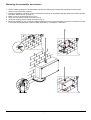
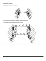
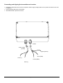
1
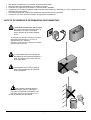
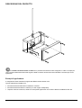
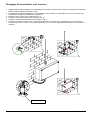
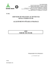
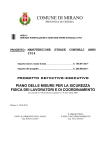
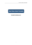
MANUALE D’USO
_________________________
OPERATING INSTRUCTIONS
MANUALE
D’USO
INDICE
INDICE.................................................................................................................................................................................... 1
INTRODUZIONE .................................................................................................................................................................... 2
Contenuto dell'imballo ............................................................................................................................................................................... 2
Contenuti di questo manuale..................................................................................................................................................................... 2
Convenzioni tipografiche ........................................................................................................................................................................... 2
DATI DI MARCATURA........................................................................................................................................................... 2
NORME DI SICUREZZA ........................................................................................................................................................ 2
NOTE DI SICUREZZA ED INFORMAZIONI SUPPLEMENTARI .......................................................................................... 3
DESCRIZIONE DEL PRODOTTO ......................................................................................................................................... 4
Esempi di applicazione.............................................................................................................................................................................. 4
Alimentazione............................................................................................................................................................................................ 5
Uso mobile ................................................................................................................................................................................................ 5
Montaggio.................................................................................................................................................................................................. 5
Frequenze operative.................................................................................................................................................................................. 5
INSTALLAZIONE ................................................................................................................................................................... 5
Prerequisiti ................................................................................................................................................................................................ 5
TARATURA CANALI E FREQUENZE ................................................................................................................................... 6
MONTAGGIO DEL TRASMETTITORE E DEL RICEVITORE .............................................................................................. 7
Casi di installazione................................................................................................................................................................................... 8
Montaggio del trasmettitore e del ricevitore........................................................................................................................................... 8
Due collegamenti radio in parallelo usando due frequenze................................................................................................................... 8
Connessioni del trasmettitore e del ricevitore ........................................................................................................................................... 9
SOLUZIONE PROBLEMI..................................................................................................................................................... 10
SPECIFICHE TECNICHE..................................................................................................................................................... 10
Dati sul sistema ....................................................................................................................................................................................... 10
Connessioni del sistema ......................................................................................................................................................................... 10
Dati generali ............................................................................................................................................................................................ 10
Trasmettitore RDDT433 .......................................................................................................................................................................... 11
Ricevitore RDDR433 ............................................................................................................................................................................... 11
Il produttore declina ogni responsabilità per eventuali danni derivanti da un uso improprio delle apparecchiature
menzionate in questo manuale; si riserva inoltre il diritto di modificarne il contenuto senza preavviso.
Ogni cura é stata posta nella raccolta e nella verifica della documentazione contenuta in questo manuale: tuttavia il
produttore non può assumersi alcuna responsabilità derivante dall’utilizzo della stessa. Lo stesso dicasi per ogni persona
o società coinvolta nella creazione e nella produzione di questo manuale.
Pag. 1
RDDR/RDDT9823/2
INTRODUZIONE
Contenuto dell'imballo
• 1 trasmettitore o ricevitore
• 1 antenna
• 1 manuale di istruzioni
Dopo la consegna, controllare se il contenuto dell'imballo è danneggiato e controllare eventuali segni o abrasioni. Nel
caso contattare immediatamente il fornitore.
Controllare che il contenuto corrisponda alla lista del materiale sopra elencata.
Contenuti di questo manuale
Questo manuale descrive il sistema di trasmissione dati via radio RDDR433 / RDDT433 assieme alle procedure per
l'installazione, configurazione e uso. Leggere questo manuale con attenzione, in particolare il capitolo riguardante le
norme di sicurezza, prima dell'installazione e dell'uso del sistema.
Convenzioni tipografiche
In questo manuale vengono utilizzati differenti simboli grafici, il senso di questi simboli è sotto descritto:
L'operazione è molto importante per il corretto funzionamento del sistema: leggere attentamente la procedura
indicata e seguire le modalità richieste.
Descrizione delle caratteristiche del sistema: leggere attentamente per capire le fasi seguenti.
Dati di marcatura
Sul sistema di trasmissione dati via radio RDDR433 / RDDT433 ci sono due etichette conformi alle
specificazioni CE.
La prima etichetta include:
• Codice identificazione modello (Codice a barre esteso 3/9 )
• Tensione di alimentazione (Volt)
• Frequenza(Hertz)
• Assorbimento energia (Watt)
La seconda etichetta mostra il numero di serie del modello (Codice a barre esteso 3/9)
Quando viene installato l’apparecchio, controllare che le specifiche riguardanti l’alimentazione del sistema di
trasmissione dati via radio corrispondano a quelle richieste. L’uso improprio può seriamente compromettere la
sicurezza del personale addetto e dell’installazione.
NORME DI SICUREZZA
Il sistema di trasmissione dati via radio RDDR433 / RDDT433 è conforme con le normative di legge in vigore
al tempo della stesura di questo manuale, riguardo sicurezza elettrica, compatibilità elettromagnetrica e altri requisiti
generali.
Si desidera tuttavia garantire gli utilizzatori (tecnico installatore e operatore) specificando alcune avvertenze per
operare nella massima sicurezza:
• L’installazione dell’apparecchio (e dell’intero impianto di cui esso fa parte) deve essere effettuata da personale
tecnico adeguatamente qualificato
• L’apparecchio deve essere aperto soltanto da personale tecnico qualificato. La manomissione dell’apparecchio fa
decadere i termini di garanzia
• Collegare ad una linea di alimentazione corrispondente a quella indicata sulle etichette di marcatura (vedere il
successivo capitolo Dati di marcatura)
• Prima di spostare o effettuare interventi tecnici sull’apparecchio, disinserire la spina di alimentazione
Pag. 2
RDDR/RDDT9823/2
•
•
•
•
Non utilizzare l’apparecchio in presenza di sostanze infiammabili
Non permettere l’uso dell’apparecchio a bambini o incapaci
Accertarsi che l’apparecchio sia fissato in maniera solida e affidabile
L’apparecchio si considera disattivato soltanto quando l’alimentazione é disinserita e i cavi di collegamento con altri
dispositivi sono stati rimossi
• Per l’assistenza tecnica rivolgersi esclusivamente al personale tecnico autorizzato
• Conservare con cura il presente manuale per ogni futura consultazione
NOTE DI SICUREZZA ED INFORMAZIONI SUPPLEMENTARI
Il sistema di trasmissione dati via radio
può essere alimentato solo attraverso un
alimentatore 12 VDC, il quale deve
essere protetto da un fusibile ritardato
da 1A .
In nessuna circostanza il sistema può essere
alimentato direttamente con un cavo di
alimentazione (p.e. 230VAC).
Ignorare queste note di sicurezza può mettere
in pericolo la vostra vita!
Una prolungata esposizione degli occhi
alle radiazioni emesse dal trasmettitore o
dalla sua antenna può essere rischioso
ai fini della salute.
Il trasmettitore ed il ricevitore possono
essere aperti solamente da personale
tecnico qualificato.
Non applicare etichette adesive,
lamine metalliche, pittura o equivalenti
coprendo le scatole del trasmettitore e del
ricevitore, perché ciò può interferire con il
corretto funzionamento del sistema.
Pag. 3
RDDR/RDDT9823/2
DESCRIZIONE DEL PRODOTTO
Il sistema trasmissione dati via radio è un prodotto tecnicamente molto sviluppato. E’ stato concepito per
l’uso nei settori della trasmissione dei segnali e della sicurezza. Nessuna licenza individuale è richiesta per la sua
operatività.
Esempi di applicazione
Il collegamento radio trasmette il segnale dati RS232 senza l'ausilio di fili.
Tipiche applicazioni possibili sono:
• trasmissione dati di telemetria tra tastiera e ricevitore
• trasmissione dati tra tastiera e matrice (con due coppie di dispositivi)
• superare ostacoli come fiumi, strade e in tutte quelle applicazioni che rendono difficile l’installazione dei cavi.
Pag. 4
RDDR/RDDT9823/2
Alimentazione
Il trasmettitore ed il ricevitore operano con un voltaggio di 12VDC. Tale voltaggio può essere fornito da una fonte
stabilizzata capace di fornire una corrente continua di almeno 0.3A, per il trasmettitore e per il ricevitore, il circuito di
alimentazione deve essere protetto da un fusibile ritardato da 1A .
Uso mobile
Se, durante l’uso mobile del sistema di trasmissione via radio via radio, nessuna erogazione di corrente è
disponibile, il trasmettitore ed il ricevitore possono essere alimentati da una batteria per auto da 12V.
Montaggio
Una scatola stagna permette ovunque facili installazioni, anche all’esterno, su muri di edifici o su alberi.
Frequenze operative
La trasmissione dei dati avviene su una frequenza tarata all'interno della gamma compresa tra i 433,875 e i 434,650
MHz, riferendosi al setup del dip-switch interno (vedi tavola a pag. 7). 32 indipendenti frequenze di collegamento sono
disponibili. Il trasmettitore ed il ricevitore devono essere tarati con la stessa frequenza.
Si prega di notare che i componenti del sistema di collegamento radio non possono essere usati come relay
stations.
INSTALLAZIONE
L’installazione deve essere eseguita solamente da personale tecnicamente qualificato.
Le seguenti procedure devono essere eseguite con l’alimentatore spento se non altrimenti specificato.
Prerequisiti
Per ottenere migliori prestazioni, il sistema deve essere installato in modo che il trasmettitore ed il ricevitore si
fronteggino senza ostacoli, cioè non ci devono essere ostacoli statici (linee dell’alta tensione, alberi, muri, edifici, etc.) o
dinamici (tramvie, ferrovie, autovie, etc.) tra le due unità.
Pag. 5
RDDR/RDDT9823/2
TARATURA CANALI E FREQUENZE
Canali
Frequenze
4 bits Switch
Jumper
Canali
Frequenze
A1
433,875
ON
ON
ON
A2
433,925
ON
ON
ON
A3
433,975
ON
ON
A4
434,025
ON
ON
A5
434,075
ON
OFF ON
A6
434,125
ON
OFF ON
A7
434,175
ON
A8
434,225
A9
4 bits Switch
Jumper
ON
ON
B1
433,900
ON
ON
ON
ON
OFF
OFF
ON
B2
433,950
ON
ON
ON
OFF
OFF
OFF ON
ON
B3
434,000
ON
ON
OFF ON
OFF
OFF OFF
ON
B4
434,050
ON
ON
OFF OFF
OFF
ON
ON
B5
434,100
ON
OFF ON
ON
OFF
OFF
ON
B6
434,150
ON
OFF ON
OFF
OFF
OFF OFF ON
ON
B7
434,200
ON
OFF OFF ON
OFF
ON
OFF OFF OFF
ON
B8
434,250
ON
OFF OFF OFF
OFF
434,275
ON
ON
ON
ON
ON
B9
434,300
ON
ON
ON
ON
OFF
A10
434,325
OFF ON
ON
OFF
ON
B10
434,350
OFF ON
ON
OFF
OFF
A11
434,375
OFF ON
OFF ON
ON
B11
434,400
OFF ON
OFF ON
OFF
A12
434,425
OFF ON
OFF OFF
ON
B12
434,450
OFF ON
OFF OFF
OFF
A13
434,475
OFF OFF ON
ON
ON
B13
434,500
OFF OFF ON
ON
OFF
A14
434,525
OFF OFF ON
OFF
ON
B14
434,550
OFF OFF ON
OFF
OFF
A15
434,575
OFF OFF OFF ON
ON
B15
434,600
OFF OFF OFF ON
OFF
A16
434,625
OFF OFF OFF OFF
ON
B16
434,650
OFF OFF OFF OFF
OFF
Sistema taratura frequenze:
Gruppo A: Jumper ON
Gruppo B: Jumper OFF
Switch: ON = “L”
OFF = “H”
Esempi:
Taratura canale A5
(434,075MHz)
Gruppo A: Jumper ON
Switch: ON, OFF, ON, ON
RDDT433
RDDR433
Pag. 6
RDDR/RDDT9823/2
Montaggio del trasmettitore e del ricevitore
1. Scegliere delle posizioni adatte per il trasmettitore ed il ricevitore, tenendo bene a mente i prerequisiti descritti nella
sezione relativa. Marcare le posizioni scelte.
2. L’orientamento ideale dell’installazione del trasmettitore e del ricevitore è “orizzontale” (con il cavo sul fondo: vedi
l’illustrazione “Esempio di installazione” a pagina 5).
3. Eseguire 4 fori sul muro come mostrato in Fig. A.
4. Avvitare il fondo della scatola come mostrato in Fig. B.
5. Avvitare il coperchio della scatola come mostrato in Fig. C.
6. Dovunque possibile, stendere i cavi di connessione attraverso la muratura; se il trasmettitore o il ricevitore sono
montati su di un muro. In tutti i casi, prestare attenzione che i cavi siano adeguatamente protetti da, ad esempio, un
condotto.
Alternativa
Pag. 7
RDDR/RDDT9823/2
Casi di installazione
Montaggio del trasmettitore e del ricevitore
Trasmettitore
Ricevitore
La massima distanza che garantisce il funzionamento tra trasmettitore e ricevitore è di 700m.
Due collegamenti radio in parallelo usando due frequenze
Se si desidera usare due sistemi di trasmissione dati via radio simultaneamente ed in parallelo, un sistema dovrà
utilizzare una differente frequenza di comunicazione (sono disponibili fino a 32 diverse frequenze).
Pag. 8
RDDR/RDDT9823/2
Connessioni del trasmettitore e del ricevitore
• Connettere l’ingresso dati in RS232 al trasmettitore.
• Prelevare l’uscita dati in RS232 dal ricevitore.
• Connettere il trasmettitore ed il ricevitore a diverse alimentazioni 12VDC (filo bianco al terminale positivo, filo
marrone al negativo).
Alimentazione
(12VDC)
RS232
verde (DATA)
bianco (GND)
marrone (-)
marrone (GND)
bianco (+)
Pag. 9
RDDR/RDDT9823/2
SOLUZIONE PROBLEMI
Problemi
Il ricevitore non funziona
Cause possibili
Alimentatore 12VDC per trasmettitore
e ricevitore mancante
Trasmettitore e ricevitore trasmettono
in differenti frequenze
Segnale radio (parzialmente) deviato
da alberi, edifici, veicoli, etc.
Trasmettitore e ricevitore troppo
distanti
Cavo rotto o tagliato nella connessione
con trasmettitore o ricevitore
Rimedi
Connettere il trasmettitore ed il ricevitore
all’alimentatore 12VDC
Modificare il trasmettitore o il ricevitore
Montare il trasmettitore/ricevitore in una
posizione più favorevole (vedi la sezione
“Prerequisiti”)
Installare il trasmettitore e ricevitore
cosicchè la distanza massima tra le due
unità non ecceda quanto specificato
nella sezione “Dati tecnici”
Il cavo difettoso deve essere rimpiazzato
dal personale di servizio
SPECIFICHE TECNICHE
Dati sul sistema
Stabilità di frequenza
Segnali in ingresso e in uscita
Modulazione
Comunicazione
Tipo
±2 KHz
RS232,1200 Baud max.
FM stretta
Una via
PLL synthesizer
Connessioni del sistema
Connessione cavo “DATI”
Connessione cavo“12VDC”
lungo 2 m con finali aperti (tre-poli)
lungo 2 m con finali aperti (due-poli)
Dati generali
Temperatura di utilizzo
Temperatura di immagazzinamento
Umidità relativa
Protezione del contenitore
Dimensioni del contenitore
Lunghezza antenna
Peso
Pag. 10
-10°C...+60°C
-20°C...+65°C
Max. 90%
IP 54 (protezione contro
gli spruzzi d’acqua)
200 mm x 200 mm x 60 mm
170mm
0.4 kg
RDDR/RDDT9823/2
Trasmettitore RDDT433
Frequenza standard (nominale)
Passo tra i canali
Numero di canali
Potenza output EIRP
Antenna del trasmettitore
Apertura angolo dell’antenna
Voltaggio dell’alimentazione
Massimo assorbimento corrente
434,650 MHz
25 KHz
32
10 mW
fissa
omnidirezionale
12VDC
50 mA
Ricevitore RDDR433
Frequenza standard (nominale)
Passo tra i canali
Numero di canali
Potenza necessaria di ricezione (isotropica)
Antenna del ricevitore
Apertura angolo dell’antenna
Voltaggio dell’alimentazione
Massimo assorbimento corrente
434,650 MHz
25 KHz
32
≥-84 dBm
fissa
omnidirezionale
12VDC
50 mA
QUESTO PRODOTTO È SOLO PER ESPORTAZIONE FUORI DALLA CEE.
Pag. 11
RDDR/RDDT9823/2
OPERATING
INSTRUCTIONS
INDEX
INDEX..................................................................................................................................................................................... 1
INTRODUCTION .................................................................................................................................................................... 2
Packing contents ....................................................................................................................................................................................... 2
Contents of this Manual............................................................................................................................................................................. 2
Typographic conventions........................................................................................................................................................................... 2
IDENTIFICATION DATA ........................................................................................................................................................ 2
SAFETY RULES .................................................................................................................................................................... 2
SAFETY NOTES AND ADDITIONAL INFORMATION.......................................................................................................... 3
PRODUCT DESCRIPTION .................................................................................................................................................... 4
Application example .................................................................................................................................................................................. 4
Power supplies .......................................................................................................................................................................................... 5
Mobile use ................................................................................................................................................................................................. 5
Mounting.................................................................................................................................................................................................... 5
Operating frequencies ............................................................................................................................................................................... 5
INSTALLATION ..................................................................................................................................................................... 5
Prerequisites ............................................................................................................................................................................................. 5
CHANNEL AND FREQUENCY SETTING ............................................................................................................................. 6
MOUNTING THE TRANSMITTER AND RECEIVER............................................................................................................. 7
Installation examples................................................................................................................................................................................. 8
Mounting the transmitter and receiver ................................................................................................................................................... 8
Two radio link systems in parallel using two channels .......................................................................................................................... 8
Connecting and aligning the transmitter and receiver ............................................................................................................................... 9
TROUBLE SHOOTING ........................................................................................................................................................ 10
SPECIFICATIONS................................................................................................................................................................ 10
System data ............................................................................................................................................................................................ 10
System connections ................................................................................................................................................................................ 10
General data............................................................................................................................................................................................ 10
Transmitter RDDT433 ............................................................................................................................................................................. 11
Receiver RDDR433 ................................................................................................................................................................................. 11
The manufacturer declines all responsibility for any damage caused by an improper use of the appliances mentioned in
this manual; furthermore, the manufacturer reserves the right to modify its contents without any prior notice.
The documentation contained in this manual has been collected with great care: the manufacturer, however, cannot
take any liability for its use. The same thing can be said for any person or company involved in the creation and
production of this manual.
Pag. 1
RDDR/RDDT9823/2
INTRODUCTION
Packing contents
• 1 transmitter or receiver
• 1 antenna
• 1 instruction manual
After the delivery, check that the packing is not damaged and shows no evident signs of falls or abrasion. Should this
be so, contact immediately the supplier.
Check that the contents correspond to the above-mentioned list of materials.
Contents of this Manual
This manual describes the data wireless system RDDR433/RDDT433 together with its specific procedures of
installation, configuration and use. Read this manual carefully, in particular the chapter concerning the safety rules,
before installing and using the wireless system.
Typographic conventions
Different graphic symbols are used in this manual, the meaning of which is here described:
Hazard of electric shock; disconnect the power supply before proceeding, if not otherwise specified.
The operation is very important for the correct working of the system: read carefully the procedure indicated,
and carry it out according to the required modalities.
Description of system features: read carefully to understand the following phases.
IDENTIFICATION DATA
On the data wireless system RDDR433/RDDT433 there are two plates complying with EC specifications.
The first plate includes:
• Model identification code (Extended bar code 3/9 )
• Mains voltage (Volt)
• Frequency (Hertz)
• Power consumption (Watt)
The second plate shows the model serial number (Extended bar code 3/9)
When installing the appliance, check that the power supply specifications of the data wireless system correspond to
those required. The use of improper appliances may seriously compromise the safety of the personnel and the
installation.
SAFETY RULES
The data wireless system RDDR433/RDDT433 complies with the normative laws in force at the time of
editing of this manual, concerning electric safety, electromagnetic compatibility and general requirements.
Anyway, in order to ensure the users (installer technician and operator), the following warnings are specified for
safety’s sake:
• Connect to a feeder corresponding to the specifications indicated on the data plate (see next chapter Identification
data)
• The outlet must be correctly earthed according to the normative laws in force
• Before any shifting or technical operations on the appliance, unplug it from the mains
• Do not use voltage cables showing wear or ageing, since they may seriously compromise the users’ safety
• The appliance (and the complete system, which it belongs to) must be installed only by qualified technical staff
• The appliance must be opened only by qualified technical staff. The tampering of the appliance may void the
guarantee terms.
Pag. 2
RDDR/RDDT9823/2
•
•
•
•
Do not use the appliance in the presence of inflammable substances
Do not allow children or people not familiar with the appliance to use it
Make sure the appliance is fixed in a solid and reliable way
The appliance is completely off-line only when the plug is diconnected and the cables connected to other appliances
have been removed
• For after-sale service call only authorised technical staff.
• Keep this manual close to hand for any future reference
SAFETY NOTES AND ADDITIONAL INFORMATION
12VDC
The data wireless system may be operate
only from a 12VDC supply, which must
be protected with
a 1A slow-blow fuse.
Under no circumstances may the system be
operated directly from the mains supply (e.g.
230VAC).
Ignoring this safety note can endanger your
life!
12VDC
Furthermore, operation from the mains will
cause irreparable damage to the system.
Prolonged exposure of the eyes to the
radiation emitted by the transmitter or its
antenna incurs a healt risk
The transmitter and receiver may be
opened only by our service and repair
personnel. Removing the sealed
screws and opening the case will
invalidate the warranty.
Do not apply adhesive labels, metalfoil,
paint or similar coverings to the case of
the transmitter or receiver, since this can
interfere with the correct operation of the
system.
Pag. 3
RDDR/RDDT9823/2
PRODUCT DESCRIPTION
The data wireless system is a highly developed technical product. It was designed specifically for charge-free
use in the sectors of signal transmission and security technology. No individual license is required for operation.
Application example
The radio link transmit RS232 data signal without wires.
Possible typical applications are:
• telemetry data transmission among keyboard and receivers
• to overcome obstacles such as rivers, roads and all applications which make difficult cables installation.
Pag. 4
RDDR/RDDT9823/2
Power supplies
The transmitter and receiver operate from a voltage of 12VDC. This can be provided by an stabilized mains adapter
capable of supplying a continuos current of at least 0.3A for the transmitter and receiver must be protected by a 1A
slow-blow fuse.
Mobile use
If, during mobile use, no mains voltage is available, the transmitter and receiver can be operated from a 12V car
battery.
Mounting
An easily mounted, weatherproof case permits installation anywhere, even outdoors on building walls or on wooden
masts.
Operating frequencies
Data transmission is performed on a frequency set in the range 433,875- 434,650 MHz,according to the internal dipswitch setup (table page 7). 32 indipendent link frequencies are available. Transmitter and receiver must be set at the
same code.
Please note that the components of the radio link system cannot be used as relay stations.
INSTALLATION
The installation must be carried out only by qualified technical staff.
The following procedures must be carried out with power supply off, if not otherwise specified.
Prerequisites
In order to obtain the best performances, the system must be installed such that there is a free line of sight between
the transmitter and receiver, i.e. there must be no static (high-tension lines, trees, walls, buildings, etc.) or dynamic
(trams, railways, trucks, etc.) obstacles between the two units.
Pag. 5
RDDR/RDDT9823/2
CHANNEL AND FREQUENCY SETTING
Channel
Frequency
4 bits Switch
Jumper
Channel
Frequency
A1
433,875
ON
ON
ON
A2
433,925
ON
ON
ON
A3
433,975
ON
ON
A4
434,025
ON
ON
A5
434,075
ON
OFF ON
A6
434,125
ON
OFF ON
A7
434,175
ON
A8
434,225
A9
4 bits Switch
Jumper
ON
ON
B1
433,900
ON
ON
ON
ON
OFF
OFF
ON
B2
433,950
ON
ON
ON
OFF
OFF
OFF ON
ON
B3
434,000
ON
ON
OFF ON
OFF
OFF OFF
ON
B4
434,050
ON
ON
OFF OFF
OFF
ON
ON
B5
434,100
ON
OFF ON
ON
OFF
OFF
ON
B6
434,150
ON
OFF ON
OFF
OFF
OFF OFF ON
ON
B7
434,200
ON
OFF OFF
ON
OFF
ON
OFF OFF OFF
ON
B8
434,250
ON
OFF OFF OFF
OFF
434,275
ON
ON
ON
ON
ON
B9
434,300
ON
ON
ON
ON
OFF
A10
434,325
OFF ON
ON
OFF
ON
B10
434,350
OFF ON
ON
OFF
OFF
A11
434,375
OFF ON
OFF ON
ON
B11
434,400
OFF ON
OFF ON
OFF
A12
434,425
OFF ON
OFF OFF
ON
B12
434,450
OFF ON
OFF
OFF
OFF
A13
434,475
OFF OFF ON
ON
ON
B13
434,500
OFF OFF ON
ON
OFF
A14
434,525
OFF OFF ON
OFF
ON
B14
434,550
OFF OFF ON
OFF
OFF
A15
434,575
OFF OFF OFF ON
ON
B15
434,600
OFF OFF OFF ON
OFF
A16
434,625
OFF OFF OFF OFF
ON
B16
434,650
OFF OFF OFF OFF
OFF
Frequency Setting Method:
Group A: Jumper ON
Group B: Jumper OFF
Switch: ON = “L”
OFF = “H”
Example:
Set to channel A5 (434,075MHz)
Group A: Jumper ON
Switch: ON, OFF, ON, ON
RDDT433
RDDR433
Pag. 6
RDDR/RDDT9823/2
Mounting the transmitter and receiver
1. Locate suitable positions for the transmitter and receiver, bearing the prerequisites mentioned in the previous
section in mind. Mark the positions.
2. The ideal installation orientation for the transmitter and receiver is “horizontal” (with the cable at the bottom: see the
illustration “Basic version” on page 5.).
3. Make 4 roles on the wall as shown in Fig. A.
4. Screw the rear of the housing as shown in Fig. B.
5. Screw the covering of the housing as shown in Fig. C.
6. Wherever possible, lay the connection cable through the masonry if the transmitter or receiver is mounted on a wall.
In all cases, take care that the cable is suitably protected by, for example, a cable duct.
Pag. 7
RDDR/RDDT9823/2
Installation examples
Mounting the transmitter and receiver
The maximum distance between the transmitter and the receiver is 700m.
Two radio link systems in parallel using two channels
If you wish to use two data wireless system simultaneously and in parallel, then one system must use different
communication codes (up to 32 channels).
Pag. 8
RDDR/RDDT9823/2
Connecting and aligning the transmitter and receiver
• Connect the transmitter and receiver to separate 12VDC supply voltage (white wire to positive terminal, brown wire
to negative).
• Connect RS232 data input to transmitter
• Take RS232 data output from receiver
RS232
Power supply
(12VDC)
green (DATA)
white (GND)
brown (-)
brown (GND)
white (+)
Pag. 9
RDDR/RDDT9823/2
TROUBLE SHOOTING
Problem
Receiver does not work properly
Possible cause
12VDC supply for transmitter or
receiver missing
Transmitter and receiver operating on
different frequencies
Radio signal (partially) blocked by
trees, building, vehicles, etc.
Transmitter and receiver too far apart
Transmitter or receiver connection
cable broken or cut
Remedy
Connect transmitter or receiver to
12VDC supply
Have the transmitter or receiver
modified
Mount the transmitter/receiver in a
more favorable position (see the
section “Prerequisites”)
Install the transmitter and receiver
so that the maximum range
specified in the “Technical data” is
not exceeded
Have the defective cable replaced
by service personnel
SPECIFICATIONS
System data
Frequency stability
Input and Output Signal
Modulation
Communication
Type
±2 KHz
RS232,1200 Baud max.
FM narrow
One way
PLL synthesizer
System connections
Connection cable “DATA”
Connection cable “12VDC”
2 m long with open ends (three-pole)
2 m long with open ends (two-pole)
General data
Ambient temperature
Storage temperature
Relative humidity
Enclosure type
Case dimensions
Antenna size
Weight
-10°C...+60°C
-20°C...+65°C
Max. 90%
IP 54 (splashproof)
200 mm x 200 mm x 60 mm
170mm
0.4 kg
Pag. 10
RDDR/RDDT9823/2
Transmitter RDDT433
Standard frequency (nominal)
Channel step
Number of channels
Output power EIRP
Transmitter antenna
Antenna aperture angle
Supply voltage
Maximum current consumption
434,650 MHz
25 KHz
32
10 mW
fix mounted
omnidirectional
12VDC
50 mA
Standard frequency (nominal)
Channel step
Number of channels
Necessary received power (isotropic)
Receiver antenna
Antenna aperture angle
Supply voltage
Maximum current consumption
434,650 MHz
25 MHz
32
≥-84 dBm
fix mounted
omnidirectional
12VDC
50 mA
Receiver RDDR433
THIS PRODUCT IS ONLY FOR EXPORT OUTSIDE CEE.
Pag. 11
RDDR/RDDT9823/2