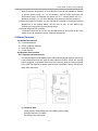
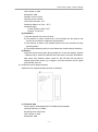
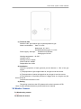
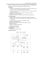
1
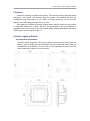
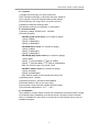
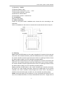
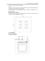
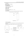
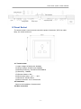
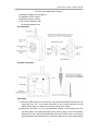
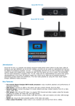
Smart home system control terminals
Smart Home Control Terminals
《USER MANUAL》
-1-
Smart home system control terminals
Content
I Preface ------------------------------------------------------------------------------------------------------- 3
II Smart Lighting Switch -------------------------------------------------------------------------------------3
2.1 Single-wire smart switch ------------------------------------------------------------------------ 3
2.2 Double-wire smart switch ----------------------------------------------------------------------- 6
III Smart Curtain Controller --------------------------------------------------------------------------------7
3.1 Single curtain controller ------------------------------------------------------------------------- 7
3.2 Double curtain controller ------------------------------------------------------------------------ 9
3.3 Curtain motor ------------------------------------------------------------------------------------ 10
3.4 Curtain track --------------------------------------------------------------------------------------10
IV Smart Socket ---------------------------------------------------------------------------------------------11
V RF to IR Converter --------------------------------------------------------------------------------------12
VI Alarm Sensors -------------------------------------------------------------------------------------------14
6.1 Wired alarm sensors ----------------------------------------------------------------------------14
6.1.1 Infrared detector -------------------------------------------------------------------------------14
6.1.2 Door magnetic detector ----------------------------------------------------------------------14
6.1.3 Smoke detector --------------------------------------------------------------------------------14
6.1.4 Gas detector ------------------------------------------------------------------------------------14
6.2 Wireless alarm sensors ------------------------------------------------------------------------14
6.2.1 Infrared detector ------------------------------------------------------------------------------ 14
6.2.2 Door magnetic detector ----------------------------------------------------------------------15
6.2.3 Smoke detector --------------------------------------------------------------------------------16
6.2.4 Gas detector ------------------------------------------------------------------------------------16
VII Monitor Camera ----------------------------------------------------------------------------------------17
7.1 Wired analog camera ---------------------------------------------------------------------------17
7.2 Wireless IP camera -----------------------------------------------------------------------------17
VIII Scene Remote Controller ---------------------------------------------------------------------------19
8.1 Hand-held remote controller ----------------------------------------------------------------- 19
8.2 Wall remote controller -------------------------------------------------------------------------- 19
-2-
Smart home system control terminals
I Preface
Thanks for choosing our smart home system. The manual is talking about the control
terminals in the system. We sincerely hope the system and products will take the
comfortable living environment to you. While it is taking protection of you and your
property and it also brings the high-tech to your life.
We suggest you read the instruction carefully before using to know very well on how
to install and operate the system. We also are appreciated to get any feedback or
suggestion from you to improve the smart home system and products better and better.
Thanks again and take a good enjoy in it.
II Smart Lighting Switch
2.1 Single-wire smart switch
The smart switch adopts RF, single wire, learning code technology which make the
switch is easy to install and use. Meanwhile the smart switch has strong ability of
compatibility and scalability. It can be used not only separately, but also work with
whole smart home system for more functions.
-3-
Smart home system control terminals
2.1.1 Feature
(1) Single wire technology, no need neutral wire
(2) RF wireless technology, no direction with quick response
(3) Low power circuit and magnetic latching relay design
(4) Anti-lightning, anti-surge circuit, to improve security
(5) Millions of different learning codes
(6) Particular receiving circuit design, no interruption
2.1.2 Technical data
(1) Working voltage: AC220V±10% 50/60Hz
(2) Power (resistive)
CS-862x gentle touch series (x is number of gangs)
1-gang: 5~800W
2-gang: 5~400W/gang
3-gang: 5~300W/gang
CS-862xM touch series (x is number of gangs)
1-gang: 9~800W
2-gang: 9~400W/gang
3-gang: 9~300W/gang
CS-865x(M) High power series (x is number of gangs)
1-gang: 800W
2-gang: 1st gang 80~800W, 2nd gang 9~1500W
3-gang: 1st gang 80~800W, 2nd/3rd gang 9~1500W/gang
Note: for inductive lamps, the power is half.
CS-862xT dimmer series (x is number of gangs)
1-gang: 40~200W
2-gang: 40~200W/gang
Note: dimmer switch is used incandescent lamp only
(3) Standby power: <0.02W
(4) Working frequency: 303.825/315/433.92MHz
(5) Remote distance: 30m (in the open area)
(6) Connection: single wire and multiple channels output
(7) Environment temperature: -10℃~+50℃
2.1.3 Installation
The installation of smart switch is same to the traditional mechanical switch. Please
cut off power before installation and connect the wire according to the instruction.
Note: it is forbidden for shot circuit or connect the live and neutral wire to one port.
Installation diagram:
-4-
Smart home system control terminals
2.1.4 Wire connection
2.1.5 Pairing method
Single ON/OFF: Turn off the lamp first. Press the button on the switch which you will
pair for 5 seconds. Then the lamp turns ON, press the button on remote controller
within 5 seconds. The lamp will flicker twice. The Single ON/OFF pairing is finished.
Press the button again to quit pairing status.
ALL ON: Turn off the lamp first. Press the button on the switch which you will pair for
15 seconds. Then the lamp turns “ON-OFF-ON”, press the "ON" button on remote
controller within 5 seconds. The lamp will flicker twice. The ALL ON pairing is finished.
Press the button again to quit pairing status.
ALL OFF: Turn off the lamp first. Press the button on the switch which you will pair for
10 seconds. Then the lamp turns “ON-OFF”, press the "OFF" button on remote
controller within 5 seconds. The lamp will flicker twice. The OFF pairing is finished.
Press the button to quit pairing status.
Delete: Turn off the lamp first. Press the button on the switch which you will delete for
20 seconds. Then the lamp turns “ON-OFF-ON-OFF”. All the paired pad or remotes
will be deleted.
Note:
(1) Single ON/OFF means using one button on remote controller to turn on and off the
-5-
Smart home system control terminals
light. Press the button, it is on, press the button again, it is off.
(2) ALL ON means the control button only can turn on the light. ALL OFF means the
control button only can turn off the light. In the mode, it should be use two button to
control the light ON or OFF. When the smart switch is paired by tablet pad, please
make pairing ALL ON for on function and ALL OFF for off function.
(3) Each gang can pair up to 20 different codes, if make the 21st pairing, the 1st one
will be covered.
2.2 Double-wire smart switch
Double-wire smart switch needs both live wire and neutral wire connected to the
switch, which is suitable to use before decoration.
2.2.1 Technical data
CS-866x(M) gentle touch/touch series (x is number of gangs)
1-gang: 0~1000W
2-gang: 0~1000W/gang
3-gang: 0~1000W/gang
CS-868x(M) high power series (x is number of gangs)
1-gang: 0~1600W
2-gang: 0~1600W/gang
3-gang: 0~1600W/gang
Note: for inductive lamps, the power is half.
CS-867x(M) dimmer series (gentle touch/touch model, x is number of gangs)
1-gang: 40~200W
2-gang: 40~200W/gang
Note: dimmer switch is used incandescent lamp only
(3) Standby power: <0.02W
(4) Working frequency: 303.825/315/433.92MHz
(5) Remote distance: 30m (in the open area)
(6) Connection: Live wire + neutral wire
(7) Environment temperature: -10℃~+50℃
2.2.2 Installation
Same to single wire smart switch.
2.2.3 Wire connection
-6-
Smart home system control terminals
2.1.4 Pairing
Same to single wire smart switch.
III Smart Curtain Controller
3.1 Single curtain controller
The smart curtain controller adopts RF wireless technology. It receives the command
from remote controller and smart host to realize remote control works with curtain
motor and track.
3.1.1 Feature
(1) Easy to install, built-in limitation controller
(2) Safe and stable with over current protection
(3) AC power driver, no need converter
(4) Low noise dealing
(5) Belt driver, widely used in family or office
3.1.2 Technical
(1) Working voltage: AC220V±10% 50/60Hz
(2) Output voltage: AC220V±10% 50/60Hz
(3) Working frequency: 303.825/315/433.92MHz
-7-
Smart home system control terminals
(4) Sensitivity: -108dBm
(5) Remote distance: 30m
(6) Environment temperature: -10℃~+50℃
(7) Environment humidity: <85% RH
(8) Dimension: 86×86×35mm
(9) Connection: live wire + neutral wire
3.1.3 Installation
Same to smart switch
3.1.4 Wire connection
Please cut off power before installation and connect the wire according to the
instruction.
Note: it is forbidden for shot circuit or connect the live and neutral wire to one port.
3.1.5 Pairing
Open: press the OPEN button on the curtain controller for 5 seconds, the buzzer will
sound "Di", then release the button, press the OPEN button on the remote controller,
the curtain controller receives signal and sound "Di-Di", the pairing is finished. Press
the button again or after 5 sec, the controller quit pairing status.
Stop: press the STOP button on the curtain controller for 5 seconds, the buzzer will
sound "Di", then release the button, press the STOP button on the remote controller,
the curtain controller receives signal and sound "Di-Di", the pairing is finished. Press
the button again or after 5 sec, the controller quit pairing status.
Close: press the CLOSE button on the curtain controller for 5 seconds, the buzzer
will sound "Di", then release the button, press the CLOSE button on the remote
controller, the curtain controller receives signal and sound "Di-Di", the pairing is
finished. Press the button again or after 5 sec, the controller quit pairing status.
Delete: Press the button you will delete for 10 sec, the buzzer will sound "Di" at 5
sec, do not release the button, at 10 sec, the buzzer will sound "Di--" longer, then all
-8-
Smart home system control terminals
the pad or remote controller are deleted.
Note:
(1) When the curtain controller is paired by tablet pad, please make pairing OPEN for
open function and CLOSE for close function.
(2) Each gang can pair up to 20 different codes, if make the 21st pairing, the 1st one
will be covered.
3.2 Double curtain controller
The double curtain controller uses one controller to control two curtain motors and
two tracks, used for double layer curtains.
3.2.1 Installation
Same to smart switch.
3.2.2 Wire connection
-9-
Smart home system control terminals
3.2.3 Pairing
Same to single curtain controller.
3.3 Curtain motor
3.3.1 Technical data
(1) Working voltage: AC220V/50Hz
(2) Working current: 0.2A
(3) Speed: 160rpm
(4) Power: 45W
(5) IP level: IP41
(6) Environment temperature: -10℃~+50℃
3.3.2 Installation
Put the axis of the motor to the track connection port, and lock the motor by bolt.
3.3.3 Wire connection
(1) Connect the black, brown and green wires to the motor, yellow and green wires to
the ground.
(2) Change the position of black and brown wire, the motor will be reversion.
3.4 Curtain track
- 10 -
Smart home system control terminals
IV Smart Socket
The smart socket is used to remote control the power of television, DVD, fan, table
lamp, rice cooker and so on.
4.1 Technical data
(1) Input voltage: AC220V±10% 50/60Hz
(2) Output voltage: AC220V±10% 50/60Hz
(3) Working frequency: 303.825/315/433.92MHz
(4) Sensitivity: -108dBm
(5) Remote distance: 30m
(6) Environment temp.: -10℃~+50℃
(7) Dimension: 86×86×35mm
(8) Wire connection: Live + Neutral wire
4.2 Installation
Same to the installation of smart switch.
4.3 Wire connection
- 11 -
Smart home system control terminals
4.4 Pairing
Same to the pairing method of smart switch.
V RF to IR Converter
RF2IR is one important device in smart home system. Most of the old home
appliances are controlled by infrared remote, like television, set top box, air conditioner
which are only controlled point to point. So RF to IR device will be easy to control IR
appliances by the system.
5.1 Technical data
(1) Model: CS-ZHQ
(2) Working frequency: 303.825/315/433.92MHz
(3) RF signal input: PT2240B 1.5~1.8MΩ OSC resistor
- 12 -
Smart home system control terminals
EV1527 180~220KΩ OSC resistor
(4) Working voltage: DC12V/300mA
(5) Standby current: ≤12mA
(6) Working current: ≤35mA
(7) RF receive distance: 30m
IR transmit distance: 8m
5.2 Installation
5.3 Wire connection
5.4 Pairing
(1) Press the SET button on the converter, the yellow LED indicator will be ON, and
sound the voice "Di-", then press the button on the remote controller, the red
LED indicator will be on when the converter receives the signal.
(2) While the red LED is on, put the transmitter window of IR controller onto the
converter glass, and press the button which need to learn on the IR controller,
after about 1.5 sec, the red LED will flicker and sound "Di-Di" voice. It means the
pairing finished. Press again the RF controller or after 60 sec it quit pairing status.
- 13 -
Smart home system control terminals
Note: if learn the temperature of air conditioner, it should use multiple RF buttons
to pair the button temp + or - on IR controller. One RF button just learn one
temperature point, for example one button for 22℃, another button for 24℃...
Because the temp + or - will send different code while it is pressed next.time.
(3) When the pairing is finished, you can use the RF controller to control the infrared
appliances. In the pairing status, the the time is over 15 sec without any
operating, the device will quit the pairing status.
(4) Delete the paired RF controller
Press the button SET for 10 sec, the red LED will be on and sound "Di-Di" voice
which means all the paired remote controller are deleted.
VI Alarm Sensors
6.1 Wired alarm sensors
6.1.1 Infrared detector
6.1.2 Door magnetic detector
6.1.3 Smoke detector
6.1.4 Gas detector
6.2 Wireless alarm sensors
6.2.1 Wireless infrared detector
The detector adopts high-stable sensor and advanced signal analysis technology.
It has strong detecting and against false positives function. When the security
area is triggered, it will detect the activity in the security area and send message
to the host.The detector is widely used at home, apartment, factory, warehouse,
shop, office and so on.
(1) Technical data
Power supply: DC9V battery/DC12V 300mA power supply
Working frequency: 315MHz
Encoding mode: fixed code
- 14 -
Smart home system control terminals
OSC resistor: 4.7MΩ
Modulation: ASK
Standby current: ≤70uA
Working current: ≤35mA
Low power indication: ≤7V
Detecting distance: 8~12m(25℃)
Detecting angle:
Curtain infrared: 100°H 10°H
Infrared: 110°H 60°V
(2) Installation
1) Put the detector in the security area.
2) The detector is used in indoor area, 2~2.5m height over the ground, and
far with air conditioner, refrigerator, and fireplace.
3) The detector is better to be installed same level to the windows for best
detecting effect.
4) The tangent detecting effect is much better than radial direction detecting.
(3) Pairing
Login the smart home system through tablet PC. Enter the settings "System
→Defense zone" select one defense zone and write in the basic information,
after press "Get address" button, power on the PIR (the PIR will send a
testing signal when power on) or trigger it, the host receives the RF signal
and read the code out.
6.2.2 Wireless door magnetic detector
Install the door magnetic beside the door or windows.
(1) Technical data
Power supply: DC9V battery/DC12V 300mA power adapter
Working frequency: 315MHz
Encoding mode: fixed code
OSC resistor: 4.7MΩ
Modulation: ASK
- 15 -
Smart home system control terminals
Standby current: ≤4mA
Working current: ≤32mA
Low power indication: ≤8V
Output power: 16dBm
(2) Installation
The door magnetic is composed by two parts, smart part is a magnetic and
the big one is sensor. It is usually installed beside the door or windows, stick
one part on the door and the other part on the doorframe. When the two part
are separated, the sensor will transmit the RF signal to the host.
(3) Pairing
The pairing is similar to the PIR, please refer to the instruction of PIR.
6.2.3 Wireless smoke detector
(1) Technical data
Alarm sensitivity: level L
Standby current: 15uA
Alarm current: 20~50mA
Alarm loudness: 90dB
Working voltage: DC9V
Working frequency: 315MHz±0.075MHz
Transmit distance: 200~1000m
Working temperature: -10℃~45℃
Humidity: ≤95℃
(2) Installation
Fix the bracket onto the wall or ceiling, then put the main unit to the bracket,
clamp it tight by counterclockwise.
While power on, the LED indicator flicker every minute, or not, please check
the power.
Press and hold the testing button for 3~5 sec, the detector will sound siren
voice and transmit RF signal, as well as the LED indicator flickers
continuously.
(3) Pairing
The pairing is similar to the PIR, please refer to the instruction of PIR.
6.2.4 Wireless gas detector
- 16 -
Smart home system control terminals
(1) Technical data
Sensitive Gas: gas, Natural gas, Liquefied petroleum gas
Alarm concentration: Gas: 0.1~0.5%
Natural gas: 0.1~0.3%
Liquefied petroleum gas: 0.1~0.2%
Power supply: wall style:
AC220V±10% 50/60Hz
Ceiling style: DC12V
Working temperature: -10~50℃
Humidity: ≤97%
Working current: 100mA
Alarm loudness: ≥85dB
Responsible time: ≤20s
(2) Installation
Check the proportion of each gas and put the detector in 1.5m of the gas
source.
1) The proportion of gas is lighter than air, the gas is over the source.
2) The proportion of natural is bigger than air, the gas is over the source.
3) The proportion of liquefied petroleum is bigger than air, the gas stay the
below of the air.
Connect the unit and fix it well.
(3) Pairing
The pairing is similar to the PIR, please refer to the instruction of PIR.
Note: for other wireless detectors, please read its user manual.
VII Monitor Camera
7.1 Wired analog camera
******
7.2 Wireless IP camera
- 17 -
Smart home system control terminals
Wireless IP camera has dome, gun, PTZ different models. The installation and
settings are similar. The following example is indoor PTZ camera.
7.2.1 Notice
(1) Keep this IP camera away from super-cooled or super-hot environment, and
other environment might effect the physical performance.
(2) Please install the IP camera horizontally and firmly, never place any other
devices on IP camera.
(3) Please do not touch the power source or IP camera with wet hand.
(4) Please do not open the housing.
(5) Please do not move the IP camera overmuch when power supply is on.
7.2.2 Technical data
(1) High performance SOC processor, stability and low power consumption.
(2) Adopt H.264 video encode technology, high compression ratio and high
quality image.
(3) Complete network protocol, built in web browse function.
(4) Support mobile phone monitor
(5) Support PTZ control, alarm I/O, double way talk etc. function
(6) Audio input/output
(7) RTSP, VLC stream media protocol
(8) Support SD card storage
(9) Support WI-FI connection
7.2.3 Installation
Install the camera to wall or ceiling.
7.2.4 Port instruction
- 18 -
Smart home system control terminals
(1) [DC 12V]: Power input
(2) [Network]: RJ-45 interface, with two lights
(3) [State]: The indicator light flash means the IP camera works
[PWR]: Red light on means the power is on.
(4) [RST]: Default to factory settings
(5) [Aout]: Audio output
(6) [Ain]: Audio input
(7) [SW]: Emergency switch
(8) [Alarm IN]: Alarm input
[G]: ground
[Alarm OUT]: Alarm output
[RS485]: Connect PTZ device to IP camera
(9) [WIFI]: Green light flashes means the WIFI connection is ok.
(10) [SIM]: SIM card slot
(11) [SD card]: SD card slot
(12) [ANT]: Wireless antenna
7.2.5 Settings
Please refer to the chapter of camera settings in the user manual of smart host.
VIII Scene Remote Controller
8.1 Hand-held remote controller
The remote controller adopts RF and learning code technology,
works with smart switch, smart socket, curtain controller etc., it can
control the light or appliances single ON/OFF, all ON, all OFF and
scene control.
8.1.1 Technical data
Working voltage: DC12V (23A12V battery)
Working current: 30mA
Working error: 303.825/433.92MHz
Frequency difference: ±75KHz
Modulation: AM
8.1.2 Operating
Single ON/OFF: Press the button on controller, the light will be on, press again,
the light will be off.
Dimming: While the light is ON, press and hold on the button on the controller, the
light will be dimming down, press and hold on the button again, the
light will be dimming up (the dimmer switch is needed).
ALL ON: Press the "ON" button to turn on all the lights (need to preset).
ALL OFF: Press the "OFF" button to turn off all the lights (need to preset).
Scene control: preset a group of lamps, curtains, appliances to one button, then
press the scene button to start the scene.
8.1.3 Pairing
Refer to the control terminals.
8.2 Wall remote controller
- 19 -
Smart home system control terminals
The remote controller looks like a switch, which is also installed to the wall, but it is a
kind of remote controller which is powered by live and neutral wires (or battery).
Each button of the controller has same function to the hand-held remote controller,
so it can be used to realize double way control, triple way control or multiple way
control and scene control.
8.2.1 Technical data
Working voltage: DC9V/AC220V
Working current: 30mA
Working frequency: 303.825/433.92MHz
Frequency error: ±75KHz
Modulation: AM
Buttons: 1/2/3/5
8.2.2 Installation
Same to smart switch.
8.2.3 Pairing
Refer to the control terminals.
- 20 -