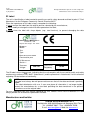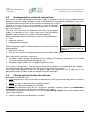
1
BIOLOGICAL PURIFICATION SYSTEMS
FOR CIVIL SEWAGE AND SIMILAR WASTES
AND FOR CARWASH DISCHARGES
OPERATING INSTRUCTIONS
Document code: AD98IU01-2_EN_R2
DECLARATION OF CONFORMITY
with the “machine” directive and arrangements for implementation
(in compliance with Art. 2 – section 2, letter a of Italian law no. 459/96)
The Manufacturer:
Omnia Resina Mazzotti S.r.l.
VIA MOLINELLO, 10/B – 48010 BAGNARA DI ROMAGNA (RA) - ITALY
Declares that the following machine
Model:
Type:
Year of manufacture:
Machine number
Complies with the arrangements outlined in the machine directive (EEC Directive 98/37)
and the following national arrangements for its implementation:
Italian Presidential Decree no. 459 dated 24/07/1996
Regulations for implementation of EEC Directives 89/392, 91/368, 93/44 and 93/68 harmonizing the
legislation of the member states regarding machinery.
and also complies with the arrangements in the following European directives:
EEC 89/336: European Council Directive issued on 3rd May 1989 harmonizing the legislation of the
member states regarding electromagnetic compatibility.
EEC 73/23: European Council Directive issued on 19th February 1973 harmonizing the legislation of
the member states regarding electrical materials to be used within certain voltage limits.
It complies with the arrangements in the following harmonized standards:
UNI EN 292/1, UNI EN 292/2,
CEI EN 60204-1, EN 60529
Bagnara di Romagna (RA), lì
Code
ISTRUZIONI USO AD98IU012_EN_R2.doc
Biological Purification Systems for civil sewage and
similar wastes and for carwash discharges
ID Label
The unit is identified by a label created to meet the essential safety demands outlined at point 1.7.3 of
Attachment I to the European Community Council Directive 98/37.
Given the importance of this label, always remember the following:
a) never remove the label from the original position selected by the manufacturer;
b) never modify or change the technical data reported on the label;
c) never clean the label with sharp objects (e.g.: steel brushes), to prevent damaging the data
reported.
Omnia Resina Mazzotti S.r.l.
Via Molinello, 10/B
Bagnara di Romagna - RA - ITALY
MODELLO
Model
TIPO
Type
ANNO DI COSTRUZIONE
Construction year
N° MATRICOLA
Serial n°.
TENSIONE
Voltage
230 VAC
FREQUENZA
Frequency
50 HZ
The ID label carries the
mark, indicating that the unit complies with the essential health and safety
requirements outlined in EEC 98/37 (Attachment I) and the procedure in Attachment V of this directive
regarding CE declarations of conformity.
NOTE
The label must always be well preserved to ensure that all the data contained is perfectly
legible.
If the label deteriorates with use, if even one piece of information is no longer legible,
contact the manufacturer for a new label providing the data contained in the present
instructions or on the original label.
For any information you may require regarding the unit, contact Omnia Resina Mazzotti S.r.l. and
always provide the ID elements reported on the label.
Manufacturer and builder
Omnia Resina Mazzotti S.r.l.
Via Molinello 10/B 48010 Bagnara di Romagna (RA) ITALY
Tel. +39 0545 76037 – Fax. +39 05454 76539
E-mail: [email protected] Web site: www.orm.it
Page I
Code
ISTRUZIONI USO AD98IU012_EN_R2.doc
Biological Purification Systems for civil sewage and
similar wastes and for carwash discharges
Edition
AD98IU01-2_EN_R2
Code
Edition
January 2006
Operating instructions created by:
Via Firenze, 3 – 48018 Faenza (Ravenna), Italy. Tel.: (+39) 0546 667906 – Fax: (+39) 0546 687350
E-mail: [email protected] - Web site: www.faentia-consulting.com
MANUAL REVISIONS
Revision
Edition
Performed by
Approved by
R0
March 2005
M.R.
G.C.
Object
R1
June 2005
O.R.M. (RGQ)
O.R.M. (DIR)
Updating following RAC indications
R2
January 2006
O.R.M. (RGQ)
O.R.M. (DIR)
Delete TÜV marking
First issue
R3
R4
Page 2
Code
ISTRUZIONI USO AD98IU012_EN_R2.doc
Biological Purification Systems for civil sewage and
similar wastes and for carwash discharges
Table of Contents
1
Preliminary works........................................................................................................................ 4
1.1
Pit ...................................................................................................................................... 4
1.2
Machine room and accessory works................................................................................... 4
1.3
Workplace lighting.............................................................................................................. 4
2
Handling and transport................................................................................................................ 5
2.1
Lifting the tank.................................................................................................................... 5
2.2
Diaphragm air compressor or motor-driven pump............................................................... 5
3
Installation, operation and use .................................................................................................... 6
3.1
Installation.......................................................................................................................... 6
3.2
Arrangement for electrical connections............................................................................... 8
3.3
Checks and verification for safe use ................................................................................... 8
3.4
Connection to power supply and plant start-up ................................................................... 9
3.5
Noise.................................................................................................................................. 9
3.6
Emergency shutdown......................................................................................................... 9
3.7
Shutting down and leaving the plant ................................................................................... 9
4
Troubleshooting ........................................................................................................................ 10
5
Scheduled and special maintenance ......................................................................................... 11
5.1
Warnings.......................................................................................................................... 11
5.2
Precautions to be taken prior to scheduled and special maintenance ............................... 11
5.3
Scheduled maintenance ................................................................................................... 12
5.3.1
Checking submerged motor-driven pump function (if present)...................................... 12
5.3.2
Checking flow regulator (if present).............................................................................. 12
5.3.3
Checking and cleaning air diffusers (if present)............................................................ 12
5.3.4
Checking and cleaning the air-lift (sludge recycle, if present) ....................................... 12
5.3.5
IMHOFF-type septic tanks ........................................................................................... 12
5.3.6
Checking oil and grease separation tanks.................................................................... 12
5.3.7
Checking oil separation tanks with coalescence filters ................................................. 12
5.4
Special maintenance ........................................................................................................ 12
5.5
Electricity-free maintenance ............................................................................................. 13
5.5.1
Procedure for setting the unit in maintenance mode..................................................... 13
ATTACHED
TECHNICAL INFORMATION Suggested method for installing – Specification headings
Page 3
Code
ISTRUZIONI USO AD98IU012_EN_R2.doc
1
Biological Purification Systems for civil sewage and
similar wastes and for carwash discharges
Preliminary works
READ
TECHNICAL INFORMATION Suggested method for installing – Specification headings
1.1
Pit
1.2
Machine room and accessory works
1.3
Workplace lighting
Before digging the pit, check for underground users (e.g. telephone lines, water or gas mains) or
overhead lines (e.g. electrical networks) in the vicinity which could hinder movement and installation
operations.
Dig a pit of adequate size (considering dimensions approximately 200 mm greater than the depth and
circumference of the tank).
Check the level of the sewer in relation to the tank inlet. If the tank is below ground level (height 0.00),
fiberglass extension rings are provided upon request to ensure that the tank can be fully inspected
during scheduled and special maintenance
On the bottom of the pit, prepare a lean concrete cast reinforced with an electrowelded mesh. The
slab must be smooth and free of any upward projecting bumps, thus protecting the tank and
guaranteeing stability.
The machine room is required when the plant includes any of the following: Universal constant flow
systems, universal direct flow systems, sludge recycle clarifiers, biological system for carwash
discharges and dual system, and such components as diffusers and air-lifts that require a diaphragm
compressor (blower) to function.
The machine room must be place at a distance of no more
than 10 m max from the plant. The support base must be flat
and solid and, to prevent any sewage backflow toward the
FLOOR PLAN
blower in case of power blackout, it must be positioned at a
level higher than the contents of the tank.
Do not use in environments containing corrosive gases or in
places where the compressor could be exposed to strong,
frequent vibrations.
PERSPECTIVE
Figure 1 shows a diagram indicating the arrangement of the
machine room. The machine room, prepared by the final user,
in addition must provide:
control board or power outlets (230 Vac, 50 Hz) in
proportionate number, fit with manual knife switch (with
AD98SCA008
fuse or magnetothermal breaker)
Figure 1 Machine room (measurea cable duct with a minimum diameter of 80 mm to protect ments in mm)
the air hoses
a cable duct with a minimum diameter of 63 mm to protect the electrical wiring;
a running water tap for maintenance operations
The plant does not have any lighting devices incorporated for normal use. These are considered
unnecessary because it is an outdoor installation.
Minimum lighting must guarantee correct perception of the symbols and signs. There must always
be enough lighting to guarantee utmost operating safety.
Page 4
Code
ISTRUZIONI USO AD98IU012_EN_R2.doc
Biological Purification Systems for civil sewage and
similar wastes and for carwash discharges
2
Handling and transport
2.1
Lifting the tank
The tank must be lifted with an overhead traveling crane, crane or crane-truck using:
for tanks up to 2000 mm in diameter: cables inserted in the holes found on the tank (see Figure 2)
for tanks over 2000 mm in diameter: cables inserted in the eyebolts found on the outside edge of
the tank (see Figure 3)
The weights of the individual tanks are reported in chapter 3 of document AD98IU01-1_IT_R0 “Safety
prescriptions”.
AD98FDA002
Figure 2 Lifting with cords
AD98FDA001
Figure 3 Lifting with eyebolts
WARNING
Move and raise the empty tank, making sure that there are no liquids inside (for example
Rain water) or other materials.
WARNING
At the end of the operations check the integrity of the plant in all its parts and components.
2.2
Diaphragm air compressor or motor-driven pump
The diaphragm air compressors or motor-driven pumps are transported manually since their size and
weight permit this (see technical description in the section entitled “General description of the units”).
Page 5
Code
ISTRUZIONI USO AD98IU012_EN_R2.doc
3
Biological Purification Systems for civil sewage and
similar wastes and for carwash discharges
Installation, operation and use
READ
TECHNICAL INFORMATION Suggested method for installing – Specification headings
3.1
Installation
Before starting the unit installation operations, the operator must check that the instructions indicated
in chapter 1 have been performed as indicated and wear suitable individual protective devices
(reinforced footwear, helmet, gloves and protective clothing).
PROPPING
Before starting the propping operation, fill the tank to ¾ full with water.
WARNING
The filling operations should be carried out equally in all the compartments to avoid
counterthrust pressure on the dividing walls.
When only pedestrian traffic is allowed and class A15 lids used, the propping operation must be
performed with inert materials (sand or fine soil, free of any stones and/or other protrusions).
When the tanks are to have class D4000 lids for roadways, pedestrian zones, transit docks and
parking areas for all types vehicles, the unit must be propped up with concrete and a height greater
than the edge of the tank for supporting the weight of the cover.
CONNECTING THE COMPONENTS
Hook up the air hoses coming from the machine room and connect the electrical power supply (where
called for, see chapter 1).
CONNECTING THE BIOGAS DISCHARGE PIPE
Connect a pipe to the biogas outlet and run it upward to dissipate any unpleasant odors that could
develop inside the tank. To this purpose it is possible to use plastic pipes connected into the downpipe
and, as a last alternative, even the discharge column ventilation pipes. Do not force the pipe to make
narrow bends and seal the joints.
WARNING
The horizontal portion must slope toward the tank to return any condensation.
CONNECTING THE TANK
Before connecting the tank, check that:
the sewer has a siphon installed to prevent the backflow of foul odors
the slope of the sewer does not exceed 2%; if it does, intercept it with a small tank to slow down
the flow of sewage (not required for universal constant flow systems)
Inlet
connect the drains for the sewage water (WC discharges) and waste waters (wash basins and
kitchen) to the tank inlet piping
WARNING
The kitchen drains must be always intercepted by an oil-grease separation tank.
do not run rainwater and waters used to wash out water softening resins into the purification
system
Outlet
connect the system discharge to an inspection tank with a slope of approximately 2%
convey the discharge from this tank to the final receiver
Page 6
Code
ISTRUZIONI USO AD98IU012_EN_R2.doc
Biological Purification Systems for civil sewage and
similar wastes and for carwash discharges
REGULATING FLOW RATE
Flow rate is regulated for the universal constant flow systems and for biological systems for the
treatment of carwash discharges.
Connect the motor-driven lift pump to the inside of the protection grid.
Check that the float movement is not blocked.
Connect the delivery pipe of the motor-driven pump to the flow distributor and regulate using the
supplied container (the level, indicated on the container, corresponds to the amount of sewage to be
transferred into the oxidation compartment in the amount of time indicated on the container label and
on the instruction sheet);
measure the flow rate;
if the flow does not match the level indicated in the container in the set amount of time, loosen the
screw and slide the “pen” until the required flow has been achieved. Then lock in place once more.
REGULATING THE AERATION SYSTEM
The following plants have an aeration system: universal constant flow system, universal direct flow
system, systems with sludge recycle clarifier, biological systems for carwash discharges and dual
systems.
The diaphragm compressor is positioned in a covered, well aerated place (machine room, see
chapter 1).
The operating temperature ranges from -20 °C to +40 °C with low relative humidity. Connect the power
supply to a 230 V, 50 Hz outlet (arranged by the final user, see paragraph 3.2).
Connect the air feed hose to the plant by inserting it into the corrugated hose already running from the
machine to the plant. Then connect it internally to the air distributor and secure it with the supplied
clamps.
Finally, connect the air distributor outlets to the users (plate and cone air diffusers and air-lift or
sludge recycle).
Adjust the air distributor cock as follows:
plate air diffusers
totally open
cone air diffusers
about one quarter open
sludge recycle
about half open
LID INSTALLATION
Insert the gaskets between the lid and
the edge of the tank to prevent any
odors from seeping out (see Figure
4).
When closing the tanks with lids,
check that there are no people,
animals or things on the inside since
people and animals could suffocate or
drown.
AD98SCA020
Figure 4 Lid installation
WARNING
Do not convey non-biodegradable material to the system (cotton wool, sanitary napkins,
dental floss, etc.) so as not to prejudice the correct operation of the plant and the submersed
pump, where provided.
Page 7
Code
ISTRUZIONI USO AD98IU012_EN_R2.doc
3.2
Biological Purification Systems for civil sewage and
similar wastes and for carwash discharges
Arrangement for electrical connections
The system must be hooked up to the power supply in compliance with the rules of good technical
practice and current safety regulations using a control board or a plug/outlet combination. If you have
any doubts about the efficiency of the network, do not plug the system in.
To plug in the unit, the user must arrange a system of industrial
outlets with a cut-off switch that can be locked and a fuse-holder
base (see Figure 5).
The user must also install an adequate knife switch on the power
supply line upstream of the system; there must also be effective
protection against overcurrent surges and indirect contacts.
Effective protection against overcurrent surges can be provided by:
fuses
automatic switches
magnetothermal switches
Effective protection against indirect contacts, on the other hand, can AD98FDB005
Figure 5 Electrical outlet arbe provided by:
rangement
differential switches
fault sensors outside the engineering room (warning light and/or sound)
When making the connection, check that:
the power supply voltage corresponds to the voltage and frequency indicated on the ID label
(using the wrong voltage could damage the unit)
the power supply network has an adequate ground system
The systems are fitted with a "too full" device that prevents problems of overflowing of the sewage in
the event the electricity temporarily fails and/or the“ electropump malfunctions.
The voltage and frequency values for the power supply are indicated on the ID label and in the
paragraph entitled “ID label” found at the beginning of this document.
3.3
Checks and verification for safe use
Remember, the operator must:
never tamper with or alter the function or effectiveness of the guards and safety devices found on
the unit
always be vigilant, attentive and have prompt reflexes
always be in perfect psychophysical condition
Before starting operations with the unit, to prevent accidents, perform checks and independent
maintenance to ensure that all the safety conditions are in place.
To facilitate the operator’s job, below is a list of the pre-start up checks that must be performed to
verify safety conditions:
carefully read the present operating instructions
Page 8
Code
ISTRUZIONI USO AD98IU012_EN_R2.doc
Biological Purification Systems for civil sewage and
similar wastes and for carwash discharges
check that the unit has been plugged into a power supply that matches the specifications indicated
by the manufacturer. Carefully check the voltage rating
the power supply must have an adequate knife switch installed upstream of the line and must have
an effective protection against overcurrent surges and indirect contacts (to be provided by the final
user, see Figure 5)
At the time the unit is hooked up, check that:
the voltage of the power supply mains corresponds to the voltage and frequency rating indicated
on the unit
the power supply mains have an adequate ground system
DANGER OF ELECTROCUTION
Never plug the unit into a power supply other than the one indicated by the manufacturer. In
case of doubt, do NOT plug the unit in.
Use the unit only in the configuration indicated by the manufacturer
Always follow the instructions and warnings reported by the pictograms applied to the unit
NO SMOKING
When performing operations, to ensure the best possible reflexes, the operator’s hands
must be free, unencumbered by foreign, dangerous objects.
For this reason, smoking is not allowed while operating the unit.
3.4
Connection to power supply and plant start-up
3.5
Noise
3.6
Emergency shutdown
3.7
Shutting down and leaving the plant
With the cut-off switch set to OFF, plug the unit into the
arranged outlet (see Figure 6) as described in paragraph 3.2.
Then turn the switch to ON to start up the system.
The only elements that generate noise are the diaphragm air
compressor blowers for the machine’s pneumatic power
supply. The noise generated runs from 31 dBA for model
HP20 to 46 dBA for model HP200.
AD98FDB005
If an emergency situation arises, the operator can cut off the Figure 6 Connection to power supply
unit by turning the outlet switch to OFF and unplugging the
unit from the outlet. This operation causes the motor-driven submersed pump and the diaphragm
compressor to stop but does not cut off the power supply from the mains.
To shut down the plant, follow the procedure indicated below:
turn the cut-off switch on the outlet to off and lock it in this position (see Figure 5)
clean the worksite so that there are no tools or other equipment set in an unstable position that
could constitute a danger. Then lock the machine room
Page 9
Code
ISTRUZIONI USO AD98IU012_EN_R2.doc
4
Biological Purification Systems for civil sewage and
similar wastes and for carwash discharges
Troubleshooting
Problem
The pump does not deliver
and the motor does not turn
The pump does not deliver
and the motor is running
The pump delivers a
reduced amount
The distributor does not load
the system
Blower with reduced air
delivery to the system
Blower not working
Poor insufflation of air from
the diffusers
Sludge recirculation not
working
Cause (Intervention)
Lack of electricity (Check that there is electricity)
Differential switch released (Reactivate the switch, if it goes again
contact a qualified electrician)
Blocked rotor (Check and free the rotor from any obstructions)
Motor or condenser damaged (Contact the retailer or customer
service)
Intake obstructed (Take the pump apart and clean the intake)
Feed piping blocked (Remove the obstructions in the piping)
Nonreturn valve blocked (Clean or replace the valve)
Intake partially obstructed (Take the pump apart and clean the
intake)
Force main partially obstructed (Remove the obstructions in the
piping)
Presence of solid bodies that prevent the rotor turning (Remove the
solid bodies from the rotor)
Rotor worn out (Replace the rotor)
Obstructed regulatory “tube” (Loosen the blocking system, extract
the tube, wash it and reassemble. Check the project capacity, as
illustrated in the instructions coming with the equipment)
Blocked air filter (Remove the cover and clean the filter)
Partial obstruction of the compressed air delivery pipe (Check that
the tubes have not been crushed and that there are no bottlenecks)
Compressor room poorly ventilated (Put in an air intake)
Blower working but noisy (Contact the seller or customer service)
Lack of electricity (Check that there is electricity)
Differential switch released (Reactivate the switch. If it happens
again contact a qualified electrician)
Breakage of diaphragms and magnet with intervention of internal
overload cutout (Contact the seller of customer service)
Blower (Check that the blower is working properly)
Obstruction of the air distribution tap or of the porous body of the
diffusers (Take out the diffusers and wash them with water. Check
that the air passage distribution taps are not blocked)
Obstruction in the air distribution tap or blockage in the pipes
(Check that the air passage distribution taps are not blocked and
clean the pipes)
Insufficient air for pumping (Check that the blower is working
properly and check the air feed tube seal)
Thick sludge on the bottom of the compartment (Increase the
amount of air using the regulation tap. Dismantle the circulation
system trying to shift the sludge on the bottom, put back together
and check how it runs. If the malfunction continues contact
customer services)
Page 10
Code
ISTRUZIONI USO AD98IU012_EN_R2.doc
5
5.1
Biological Purification Systems for civil sewage and
similar wastes and for carwash discharges
Scheduled and special maintenance
Warnings
WARNING
The manufacturer forbids any scheduled and special maintenance which is not specifically
mentioned in the present instructions.
All information on maintenance involves only, and exclusively, scheduled maintenance aimed at
ensuring correct daily operation of the unit.
Always make repairs using only original materials and parts as this will guarantee the safety of the
unit. If supplementary instructions are needed, or if particular problems arise, do not hesitate to
contact the manufacturer. Carefully follow all the instructions reported on the unit. This is very
important as it will prevent malfunctions that could, in turn, directly or indirectly lead to serious
accidents, injury and property damage.
Check that the tools available are suitable for the purpose. Always avoid all improper use of tools or
utensils.
5.2
Precautions to be taken prior to scheduled and special maintenance
All instructions reported in the present operating instructions must be carefully followed, starting with
the general indications for preparing the unit for maintenance.
It is essential that:
Unqualified, unauthorized personnel are not allowed access to the unit operating area
while maintenance is in progress.
Perform maintenance operations only when the unit is not running: that is, when the unit is
not powered (when applicable).
all maintenance operations must be performed with adequate lighting
all maintenance operations must be performed only when the weather is good (since the unit is
installed outdoors)
The operator must also always remember that:
those maintenance operations that require a power supply (e.g. unit troubleshooting) must only be
performed by qualified personnel
the recommended individual protection devices should be used (reinforced footwear, protective
masks with active carbon filters, gloves and protective clothing)
Never use the unit unless you have read and fully understood the content of these operating
instructions and all attachments.
Page 11
Code
ISTRUZIONI USO AD98IU012_EN_R2.doc
Biological Purification Systems for civil sewage and
similar wastes and for carwash discharges
5.3
Scheduled maintenance
5.3.1
Checking submerged motor-driven pump function (if present)
The minimum period for maintenance is biannual or quarterly depending on the size of the plant, the
type of discharge (civil sewage, industrial wastes, etc.) and use (occasional, continuous).
If the section where the motor-drive pump is installed is empty, the pump must not be running; if it is
not empty, check that the piezoelectric float is not blocked in any way.
If the float is blocked check the correct positioning of the electropump and the float.
5.3.2
Checking flow regulator (if present)
Check the flow rate on the regulator. If it does not correspond to what is indicated in the instructions
for its regulation, clean out the flow distributor (shut down the motor-driven lift pump, remove the end
of the delivery pipe, wash it out with water and reinstall everything before starting up the pump once
more). Then check that the flow rate matches the setting given in the instructions.
5.3.3
Checking and cleaning air diffusers (if present)
Check the air diffusers (whether plate or cone models) to ensure that they bubble the sewage
correctly. If bubbling is not uniform, withdraw the diffusers from the tank by holding onto the pneumatic
connection piping. Clean by spraying them with water and check that there are no solid foreign bodies
in the nozzles. Then return them to their original position in the tank.
5.3.4
Checking and cleaning the air-lift (sludge recycle, if present)
Check the air-lift. If it is not functioning properly, withdraw it from the purification tank, clean it by
spraying it with water and check that there are no solid foreign bodies in the inside the intake hole.
Then return it to its original position in the tank.
5.3.5
IMHOFF-type septic tanks
Periodically check the material that has settled in the digestion chamber and the material floating in
the tank. If there is too much material, run a self-purge to clean out the tank.
5.3.6
Checking oil and grease separation tanks
The following operations are to be performed:
•
every four months: inspect the tank and check that the layer of suspended grease does not
impede flow between compartments;
•
transfer the separated grease into the storage chamber;
•
when necessary, have the oil storage chamber cleaned out by a specialized company authorized
for such work.
5.3.7
Checking oil separation tanks with coalescence filters
Periodically check the separation unit to determine when it is necessary to:
open the valve to let the separated oil flow into the storage cylinder: to be performed when a
substantial layer of oil is accumulated in the tank and there is a lull in operations (a period of
minimum discharges: e.g. during the evening hours or at the end of production activities)
withdraw the filters and wash them with water
have the oil storage chamber cleaned out by a specialized company authorized for such work
5.4
Special maintenance
WARNING
Special maintenance of the unit can only be performed by authorized Omnia Resina
Mazzotti S.r.l. service centers.
Page 12
Code
ISTRUZIONI USO AD98IU012_EN_R2.doc
Biological Purification Systems for civil sewage and
similar wastes and for carwash discharges
5.5
Electricity-free maintenance
5.5.1
Procedure for setting the unit in maintenance mode
To turn off the unit to perform electricity-free maintenance, proceed as follows:
turn the cut-off switch on the outlet to off and lock it
clean the worksite so that there are no tools or other equipment set in an unstable position that
could constitute a danger
post a sign that reads “UNDER MAINTENANCE”
UNAUTHORIZED PERSONS NOT ADMITTED
Never let unauthorized persons approach the unit while under maintenance.
5.5.1.1
Checking the elements securing electrical components for tightness
AT LEAST ONCE A YEAR check the clamping of the general sorter (to be installed by the end user).
5.5.1.2
Replacing a motor-driven submersed pump
Replace the motor-driven submersed pump: do not use the unit
while the pump is out of service.
To perform this operation:
unplug the pump power supply cord
open the plug on the inspection hatch on the tank lid
lift the pump by grasping its delivery pipe (see Figure 7)
replace the motor-driven pump with another having the same
characteristics
return the pump to its original position inside the protection grid
plug the pump into the power supply outlet once more
close the lid on the tank
AD98FDB009
Figure 7 Lifting the motordriven pump
In any event refer to the instruction manual supplied with the specific equipment.
Page 13
Code
ISTRUZIONI USO AD98IU012_EN_R2.doc
5.5.1.3
Biological Purification Systems for civil sewage and
similar wastes and for carwash discharges
Replacing the diaphragm compressor (blower)
To replace the diaphragm compressor located in the machine room:
disconnect the compressor from the rest of the plant (disconnecting both electrical and pneumatic
systems)
replace with a compressor having the same technical characteristics
restore pneumatic and electrical connections
In any event refer to the instruction manual supplied with the specific equipment.
5.5.1.4
Replacing the plate-type and cone-type diffusers
The plate and cone bubbling air diffusers need to be replaced when
they are plugged. To do so, follow the operations below:
open the inspection plugs located on the tank lid, at the point
where the air diffusers are located
disconnect the hoses feeding air to the diaphragm compressor
(blower) diffusers
lift the distributor by gripping the connected pneumatic hose or
with the cord, if presents
disconnect the diffuser, replace, reconnect the pneumatic hoses
and replace inside at the tank
close the inspection plugs on the lid
5.5.1.5
AD98FDB009
Figure 8 Lifting the diffuser/s
Leaks or infiltrations between compartments of the tank and the tank itself
In the event of breakdowns and/or breakage of the tank or part of it, contact the service centres
authorised by Omnia Resina Mazzotti S.r.l.
WARNING
Special maintenance of the unit can only be performed by authorized Omnia Resina
Mazzotti S.r.l. service centers.
5.5.1.6
Evacuating the tanks
If, because of malfunctions or leaks and infiltration of the purification system, the tanks need to be
cleaned out, remember:
WARNING
Tank evacuation operations must be performed by a company specialized in cleaning septic
tanks (the substances removed must be disposed of in compliance with current law). To
prevent backpressure on the dividing walls, evacuation operations must be performed
uniformly in all compartments.
Page 14
Code
ISTRUZIONI USO AD98IU012_EN_R2.doc
Biological Purification Systems for civil sewage and
similar wastes and for carwash discharges
Suggested method for installing – Specification headings
EARTH-MOVING EXCAVATION (positioning of O.R.M. tanks above ground) all that is necessary for
the levelling and adjustment of the terrain for the formation of the support surface of the foundation
slab (cu. m.______).
1000
EXCAVATION WITH COMPULSORY SECTION (O.R.M. tanks buried) with dimensions suitable for
positioning the O.R.M. tanks (there is a surcharge with respect to the height of the tank for the
construction of the foundation), piping and winzes, whatever the nature and quality of the terrain is.
The excavations should be carried out in accordance with current safety regulations (Leg. Decree
494/96 Construction sites directives) (see diagram) (cu. m. ___).
DIAGRAM OF THE DIMENSIONS OF THE EXCAVATION
Vasca O.R.M.
700
Vasca O.R.M.
700
Vasca O.R.M.
700
Vasca O.R.M.
1000
1000
1000
Vasca O.R.M.
700
Vasca O.R.M.
700
Vasca O.R.M.
700
Vasca O.R.M.
1000
1000
1000
INSTALLATION OF THE CABLE DUCT Ø80 mm, from the engineering room to the O.R.M.
depuration plant for protecting the air pipes, including all charges for the excavation, embankment and
adjustment of the surface (m ____).
INSTALLATION OF THE CABLE DUCT Ø63 mm, from the engineering room to the O.R.M.
depuration plant for protecting the electrical pipes, including all charges for the excavation,
embankment and adjustment of the surface (m ____).
FOUNDATION made of poor concrete and electro-welded netting, average thickness 15÷20 cm,
including laying and levelling carried out with shafts or plastering, so as to eliminate any protrusions
and unevenness to ensure the tank is protected and stable (cu. m ____).
MOVEMENT of O.R.M. tank, with adequate means of hoisting, using its special hooks and positioning
on installation surface (with a ____ body).
Page 15
Code
ISTRUZIONI USO AD98IU012_EN_R2.doc
Biological Purification Systems for civil sewage and
similar wastes and for carwash discharges
FIXING of tanks that are normally empty (for example accumulation, aerobic filter)
Tanks with lower edge make 4 concrete buttress points ( see diagram) (with a ____ body).
Tanks with log bolts fix 3 log bolts to the tank and anchor them with pressure stoppers to the floor
screed in concrete. ( see diagram) (with a ____ body).
TANKS WITH LOWER EDGE
PIANTA vasca
SEZIONE vasca
TANKS WITH LOG BOLTS
PIANTA vasca
SEZIONE vasca
STRENGTHENING for pedestrian traffic with suitable material (sand or earth without stones or other
bumps), compacted for 40/50 cm thick layers which can guarantee that after compaction there will be
no empty spaces (cu.m ____).
STRENGTHENING for vehicular traffic with flat-slab concrete and a height greater than the edge of
the tank for supporting the weight of the cover. For installations with more than one tank and with a
single constrained section excavation, identify the most suitable support structure for the cover (for a
single tank, for the complete system or parts of it) and any other formwork and dismantling of the
concrete casting and carry out the embankment of the part left with suitable material (sand or earth
without stones or other bumps), compacted for 40/50 cm thick layers which can guarantee no empty
spaces (cu.m ____).
PIT FOR INSPECTION AND TAKING OF SAMPLES with dimensions of 60 x 60 cm, with bottom
sloping towards the exit; with a height that allows the difference in level between the flow in the feed
tube and the flow in the outlet tube to be at least 20 cm. Preferably position the outlet tube on the
bottom of the pit to avoid stagnation. The pit will be equipped with an input and outlet stub pipe made
of PVC Ø ____ mm; the input stub pipe will stick out inside the pit by at least 10 cm (with a ____
body).
MACHINE ROOM suitable for housing the blower(s) and the electrical panel to be made according to
the recommendations given by the Director of Works, in brickwork or reinforced concrete, on-site or
prefabricated, with dimensions of about ___ x ___ (h) ___ cm and anyway big enough to ensure an
adequate change of air to prevent the blower(s) overheating. The room will have to be ______ metres
away from the O.R.M. plant but not more than 10 metres. The support base of the room should be flat
and solid and at a higher level than that of the tank to avoid the sewage coming up to the blower. The
room will be fitted with a galvanised sheet metal window or something similar with ventilation vanes
(with a ____ body).
Page 16
Omnia Resina Mazzotti S.r.l.
Via Molinello 10/B
48010 Bagnara di Romagna (RA) - ITALY
Tel. +39 0545 76037 – Fax. +39 05454 76539
E-mail: [email protected] Sito web: www.orm.it