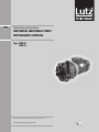
1
GB GB Operating Instructions Horizontal Centrifugal Pumps with magnetic coupling Type TMR G2 TMR G3 Read this operating instructions before start up! To be retained for future reference. GB Table of Contents 1. Safety risks........................................................................................................3 1.1 Installation and commissioning personnel..................................................4 1.2 Operators and maintenance personnel........................................................4 1.3 Repair personnel.........................................................................................4 1.4 Waste disposal............................................................................................4 1.5 Improper use..............................................................................................5 2. Identification codes............................................................................................5 3. General notes................................................................................................. 5/6 3.1 Operation in hazardous location or pumping flammable liquids.................7 4. Operating principle.............................................................................................8 5. Motor.................................................................................................................9 6. Dry running survey..........................................................................................10 7. Instructions on installation and use.................................................................10 7.1 Transport..................................................................................................10 7.2 Installation.......................................................................................... 10/11 7.3 Start-up.....................................................................................................12 7.4 Use...........................................................................................................12 7.5 Shutdown.................................................................................................12 8. Maintenance......................................................................................................12 8.1 Dismantling...............................................................................................13 8.1.1 Dismantling of series TMR G2........................................................14 8.1.2 Dismantling of series TMR G3.................................................. 15-17 8.2 Inspection.................................................................................................17 8.3 Assembly..................................................................................................18 8.3.1 Assembly of series TMR G2...................................................... 18/19 8.3.2 Assembly of series TMR G3...................................................... 20/21 9. Repairs .......................................................................................................22 10.Traceability.....................................................................................................22 11. Operating faults and possible causes..............................................................23 12.Technical data.................................................................................................24 12.1 Series TMR G2................................................................................. 24/25 12.2 Series TMR G3................................................................................. 26/27 13.Dimensions.............................................................................................. 28-33 13.1 Series TMR G2 IEC-Motors 50 Hz...................................................................................28 IEC-Motors 60 Hz...................................................................................29 NEMA-Motors 60 Hz..............................................................................30 13.2 Series TMR G3 IEC-Motors 50 Hz...................................................................................31 IEC-Motors 60 Hz...................................................................................32 NEMA-Motors 60 Hz..............................................................................33 Appendix A .......................................................................................................34 Declaration of Conformity.....................................................................................35 GB 1. Safety risks Warning! Magnetic fields Magnetic pumps contain some of the most powerful magnets in existence. The magnets are positioned on the back of the impeller and the outer magnet housing. The magnetic fields may adversely affect persons fitted with electronic devices (e.g. pacemakers and defibrillators): such persons must not be allowed to handle magnetic pumps and magnetic pump components. Warning! Magnetic force Exercise extreme caution and follow instructions carefully during pump assembly/dismantling. Magnetic force attract (cause insertion of) internal and magnetic units, and are therefore a potential source of injury to fingers and hands. Warning! Chemical hazard! The pumps are designed to pump different types of liquid and chemical. Follow the specific instructions to decontaminate during inspection or maintenance. Warning! Safety risks for personnel mainly arise from improper use or accidental damages. These risks may be of an electrical nature as far as the non-synchronous motor is concerned and may cause injury to hands if working on an open pump. Risks may also arise due to the nature of the liquids pumped. It is therefore of utmost importance to closely follow all the instructions contained in this manual so as to eliminate the causes that may lead to pump failure and the consequent leakage of liquid dangerous for both personnel and the environment. Risks may also arise from improper maintenance or dismantling practices. In any case five general rules are important: A)all services must be carried out by specialised personnel or supervised by qualified personnel depending on the type of maintenance required B)install protection guards against eventual liquid sprays (when the pump is not installed in remote areas) due to an accidental pipe rupture. Arrange for safety basins to collect possible leakage. C)when working on the pump always wear acid-proof protective clothing D)arrange for proper conditions for suction and discharge valve closing during disassembly E) make sure that the motor is completely disconnected during disassembly Proper design and building of the plants, with well positioned and well marked piping fitted with shut-off valves, adequate passages and work areas for maintenance and inspections are extremely important (since the pressure developed by the pump could give some kind of damage to the plant in case this one should be faulty made or wear and tear-damaged). It must be stressed that the major cause of pump failures leading to a consequent need to intervene is due to the pump running dry in manually operated plants. This is generally due to: - the suction valve being closed at start-up or - the suction tank being emptied without stopping GB 1.1 Installation and commissioning personnel Interventions allowed only to specialised personnel who may eventually delegate to others some operations depending on specific evaluations (technical capability required: specialisation in industrial plumbing or electric systems as needed). 1.2 Operators and maintenance personnel Interventions allowed to general operators (after training on the correct use of the plant): • pump starting and stopping • opening and closing of valves with the pump at rest • emptying and washing of the pump body via special valves and piping • cleaning of filtering elements Interventions by qualified personnel (technical capacities required: general knowledge of the mechanical, electrical and chemical features of the plant being fed by the pump and of the pump itself): • verification of environmental conditions • verification of the condition of the liquid being pumped • inspections of the control/stop devices of the pump • inspections of the rotating parts of the pump • trouble shooting 1.3 Repair personnel Interventions allowed to general operators under the supervision of qualified personnel: • stopping of the pump • closing of the valve • emptying of pump body • disconnection of piping from fittings • removal of anchoring bolts • washing with water or suitable solvent as needed • transport (after removal of electrical connections by qualified personnel) Interventions by qualified personnel (technical capacities required: general knowledge of machining operations, awareness of possible damage to parts due to abrasion or shocks during handling, know-how of required bolt and screw tightening required on different materials such as plastics and metals, use of precision measuring instruments): • opening and closing of the pump body • removal and replacement of rotating parts 1.4 Waste disposal Materials: separate plastic from metal parts. Dispose of by authorized companies. GB 1.5 Improper use The pump must not be used for purposes other than the transfer of liquids. The pump cannot be used to generate isostatic or counter pressures. The pump cannot be used to mix liquids generating an exothermal reaction. The pump must be installed horizontally on a firm base. The pump must be installed on a suitable hydraulic plant with inlet and outlet connections to proper suction and discharge pipes. The plant must be able to shut off the liquid flow independently from the pump. Handling of aggressive liquids requires specific technical knowledge. 2. Identification codes Each pump is supplied with the serial and model abbreviation and the serial number on the type label, which is riveted onto the support side. Check these data upon receiving the goods. Any discrepancy between the order and the delivery must be communicated immediately. In order to be able to trace data and information, the abbreviation, model and serial number of the pump must be quoted in all correspondence. Serial number Model Type 3. General notes "TMR" pumps are designed and built for the transfer of liquid chemical products having a specific weight, viscosity, temperature and stability of state appropriate for use with centrifugal pumps in a fixed installation, from a tank at a lower level to a tank or a pipe to a higher level. The characteristics of the liquid (pressure, temperature, chemical reactivity, specific weight, viscosity, vapour tension) and the ambient atmosphere must be compatible with the characteristics of the pump and are defined upon ordering. The max. pump’s performances (capacity, head, rpm) are defined on the identification plate. "TMR" pumps are centrifugal, horizontal, single stage, coupled to a non-synchronous electric motor via a magnetic coupling, with axial inlet and radial outlet for connection to the hydraulic system. They are foot-mounted for floor fixing. "TMR" pumps are not self priming. R1 or R2 execution “TMR” pumps can run dry. The liquid to be pumped must be clean for the R1, R2, N1 or N2 execution, the X1 or X2 execution may contain solid (%, dimension and solid part hardness must be agreed during the offer). Clockwise rotation seen from the motor side. GB Make sure that the chemical and physical characteristics of the liquid have been carefully evaluated for pump suitability. The specific weight that can be pumped at 25°C (liquid and environment) referred to max. flow (50 or 50 Hz) depend upon the type of construction: Standard construction N * 1.05 kg/dm³ Powered construction P * 1.35 kg/dm³ Strong-powered construction S * 1.80 kg/dm³ *) stamped on the rating plate The specific weight that can be pumped at 70°C is 10% less than that at 25°C. The level of kinematic viscosity must not exceed 30 cSt so as not to significantly modify the pump‘s performance. Higher values up to amaximum of 100 cSt are possible provided that the pump is equipped with suitable impeller to be defined upon ordering. The maximum continuous working temperature referred to water as well as the admissible ambient temperature depend on the choice of materials (specified on the identification plate): Execution WR GF GX Operating temperature -5 up to +80°C -30 up to +110°C -30 up to +110°C Ambient temerpature 0 up to +40°C -20 up to +40°C -20 up to +40°C The maximum pressure the pump may be subjected to is 1.5 times the head value developed with the outlet closed. The vapour pressure value of the liquid to be pumped must exceed (by at least 1m wc) the difference between the absolute total head (suction side pressure added to the positive suction head, or subtracted by the suction lift) and the pressure drops in the suction side piping (including the inlet NPSHr drops shown on the specific tables). The pump does not include any non return valve nor any liquid flow control or motor stop device. GB 3.1 Operation in hazardous location or pumping flammable liquids Danger! Operation in hazardous location or pumping flammable liquids can cause explosion resulting in severe injury or death. Use for this application only pumps of version GX with the identification II 2G T4. The identification for Ex-protection on the pump only refers to the hydraulic parts. Following must be observed: • During operation of the pump the internal space must be permanently filled with liquid to prevent that an explosive atmosphere can arise. For the start up after the filling make sure that the pumps starts to deliver right now after the starting process and that the gas which is still remaining in the internal space is exhausted. Provide respective control equipment in case this cannot be guaranteed. • Observe the limits for operating and ambient temperature. • Check the chemical compatibility of the liquid being pumped with the sealing components of the pump in order to prevent an emission of explosive gases. • Use an inlet filter. The liquid being pumped may contain max. 5% of particles. These particles are not allowed to be solid, adhesive, abrasive or of greater size than 0.1 mm. Only a small amount of particles up to a size of 0.5 mm is allowed. • Provide an equipotential bonding at the pump. Connect the equipotential bonding cable onto the earthing terminal outside of the motor housing. • The pump is not allowed to run dry. This must be secured by using a level control, a flow control or a pressure switch. • Use instruments for controlling the leakage. In case of leakage stop the pump. Observe leakage at the subsurface of the pump. • Do not operate the pump at the capacity limits of the performance curve. • Do not operate the pump with closed gate valves in suction and/or pressure line. • The pump may not be exposed to water hammer. • The pressure at the inlet or discharge side of the pump may not exceed the 1.5-fold value of that the pump creates with a closed outlet. • Before start up check the rotating direction of the pump in order to prevent that temperature exceeds due to dry running. Check the rotating direction when the hydraulic parts are disconnected, if no liquid is available. • Observe the instructions for maintenance, dismantling and assembly. • When reassembling the pump always change O-rings, V-rings and seal-rings. GB 4. Operating principle HYDRAULICALLY alike to all centrifugal pumps, it is equipped with a blade-type impeller rotating within a fixed housing. It has a tangential outlet (or radial with an internal deflector) and, by creating a depression in the center, it allows the liquid to flow from the central suction side. Then, flowing through the impeller’s blades, the fluid acquires energy and is conveyed towards the outlet. MECHANICALLY different from the traditional centrifugal pumps in the impeller motion drive thanks to the magnetic field created between the primary outer magnet and the inner magnet (not visible because housed inside the impeller hub). The magnetic field crosses the plastic parts and the liquid, and firmly couples the two magnet assemblies. When the motor causes the outer magnet to rotate together with its housing, the inner magnet assembly is dragged at the same speed. As a result the impeller, which is integral to it, is maintained in rotation. The SHAFT, totally within the housing, is not involved in the transmission of rotary motion; its only function is to act as a centering guide and support for the impeller. To this end the components are designed so that a spontaneous cooling circuit (due to a simple effect of pressure) is established to cool the surfaces subject to friction. Periodic inspections prevent the build-up of sediments between the shafts and the guide bushes significantly lengthening their working life. GB 5. Motor Electrical connections The electrical connection to the motor terminal determines the direction of rotation of the motor and can be verified by looking at the cooling fan at the rear of the motor (for the TMR pump this has to rotate clockwise looking at the front end). With single phase motors the direction of rotation may be reversed by changing the position of the connection plates: With three-phase motors the direction of rotation may be changed by swapping any two of the three conductors independently of the type of connection to the windings: The windings of three-phase motors ( e.g. with (a) 230400 V; (b) 400-690 V) require a delta-connection for lower voltage ( 230 volts for a ; 400 volts for b). They require a star-connection for higher voltage (400 volts for a; 690 volts for b). Star/Delta starting is used when the motor power is above 7.5 kW (10 HP ) only in case of frequent starts and short running times, but always when the motor power is above 15kW (20 HP ). All this is also to safeguard the structure of the pump. Protection level The initials IP are followed by two numbers: The first number indicates the level of protection against penetration of solid objects and in particular: 4 for solids whose dimension is greater than 1mm 5 for dust (eventual internal deposits will not harm operation) 6 for dust (no penetration) The second number indicates the protection against the penetration of liquids. In particular: 4 for water sprays from all directions 5 for jets of water from all directions 6 for tidal and sea waves According to the IP protection indicated on the identification plate of the motor and to the environmental conditions, arrange for opportune extra protections allowing in any case correct ventilation and rapid drainage of rainwater. GB 6. Dry running survey Though the pump can occasionally run dry (execution R1-R2), it is therefore suitable to safeguard the pump and the plant to use: • pressure switch; • level control of the container being emptied; • flow meter; • control devices for the motor power absorption. 7. Instructions on installation and use 7.1 Transport • • • • • cover the hydraulic connections when lifting the unit do not exert force on the plastic fittings lay the pump on its base or fixing plate during transport if the road is particularly rough, protect the pump by means of adequate shock absorbing supports bumps and shocks may damage important working parts vital for safety and functionality of the machine 7.2 Installation • Check that bolts and nuts are correctly screwed. (See chapter 8.3 “Assembly” for the right bolts torque setting.) Thermoplastics are dimensionally sensitive to sizeable temperature changes. • Clean the plant before connecting the pump. • Make sure that no foreign bodies are left in the pump. Remove safety caps on the hydraulic connections. • Follow the instructions indicated in the following diagram: 1) YES: gate valve (may also be near pump in the case of long piping) 2) With positive head: tilt of piping towards pump 3) Use a line strainer (3-5 mm mesh) against impurities. 4) NO: air pockets: the circuit must be short and straight 5) YES: pipe fixing parts 6) Fluid speed suction: 2.5 m/s 7) YES: check value (especially for long vertical or horizontal pipes; compulsory with parallel pumps) 8) YES: adjusting gate valve on outlet 9) Speed of delivered fluid: 3.5 m/s max. 10) YES: attachment for gauge or safety pressure switch 11) NO: elbow joints (and other parts) on the pump (discharge and suction lines) 12) With negative suction lift: tilt of piping towards suction tank 13) YES: check valve (with negative suction lift) 14) Use a strainer (3-5 mm mesh) against impurities. 15) Suction head varies according to flow in order to prevent windage (min. 0.5 m, max. 15% of pump head). 16) Suction head, 3 m max. 17) Immersion depth, 0.3 m min. 18) YES: expansion joint (indispensable with long pipes or hot liquids) and/or anti-vibration facility during discharge and suction; anchored near to pump 19) YES: pipe discharge (completely sealed), discharge value shut during normal operations 10 GB 20) YES: overcoming obstacles at lower depths 21) Fix the pump by the fixing holes provided: the supports must be level 22) YES: drainage channel around base • • • • • • • • • • • • • • • • • • • • Anchor the pump to an adequate base plate having a mass at least 5 times that of the pump. Do not use anti-vibration mounts to fix the pump. Anti-vibration joints are recommended on the pipe connections. Manually verify that all rotating parts are free to turn without abnormal friction by turning the motor cooling fan. Make sure that the power supply is compatible with the data shown on the pump motor identification plate. Connect the motor to the power supply via a magnetic/thermal control switch. Ensure that star-delta starting is implemented for motors whose power is more than 15 kW . Install emergency stop devices to switch off the pump in case of low liquid level (floating, magnetic, electronic, pressure- sensitive). Ambient temperature as a function of the physical-chemical characteristics of the liquid to be pumped and in any case not greater or lower than the interval indicated in the field of application. Other environmental conditions in accordance with the IP protection of the motor. Install a drainage pit to collect any liquid overflow from the base drainage channel due to normal maintenance work. Leave enough free space around the pump for a person to move. Leave free space above the pump for lifting operations. Highlight the presence of aggressive liquids with coloured tags following the local safety regulations. Do not install the pump (made in thermoplastic material) in close proximity to heating apparatus. Do not install the pump in areas subject to solid or liquid matter falling. Do not install the pump in an explosive atmosphere unless the motor and its coupling have been adequately prearranged. Do not install the pump in close proximity to workplaces or crowded areas. Install extra protection guards for the pump or persons as the need arises. Install a spare equivalent pump in parallel. 11 GB 7.3 Start-up • Verify that the instructions outlined in the INSTALLATION have been followed. • Verify the correct direction of rotation (clockwise from the motor side) supplying the motor with short impulses. • Ensure that the NPSH available is greater than that required by the pump (in particular for hot liquids, liquids with high vapour pressure, very long suction pipes or negative suction lift). • Close the drain valve (pos. 19); totally flood the suction pipe and the pump. • Start the pump with the suction valve completely open and the discharge valve partially closed. • Slowly regulate the flow by opening or closing the discharge valve (never the suction valve). Make sure that the power absorbed by the motor does not exceed the rated one indicated on the motor identification plate. • Do not operate the pump at the limit values of its performance curve: maximum head (discharge valve excessively closed) or maximum capacity (total absence of drops and geodetic head on the discharge side). • Set the operating point to that for which the pump was requested. • Ensure that there are no abnormal vibrations or noise due to inadequate mounting or cavitation. • Avoid short and/or frequent starts by properly setting the control devices. • Ensure that the temperature, pressure and liquid characteristics are as those specified at the time of order. • Warning!At the start-up be sure that all the internal hyfraulic parts are not in anti-clockwise rotation. The cooling fan of the motor must stand or rotate clockwise to prevent decoupling among magnetic driven parts of the pump. Add a non-return valve in the plant if the anti-clockwise rotation is due to the feed-back of the liquid in the discharge side. 7.4 Use • Switch automatic control on. • Do not activate valves whilst the pump is in operation. • Risks of dangerous water hammer effects in case of sudden or improper valve actuation (only trained personnel should operate valves). • Completely empty and wash the pump before using a different liquid. • Isolate or empty the pump if the crystallization temperature of the liquid is the same or lower than the ambient temperature. • Stop the pump if the liquid temperature exceeds the maximum allowed temperature indicated in the general notes; if the increase is of approximately 20%, check internal parts. • Close the valves in case of leaks. • Wash with water only if compatible from the chemical point of view. As alternative use an appropriate solvent that will not generate dangerous exothermal reactions. • Contact the liquid supplier for information on the appropriate fire precautions. • Empty the pump in case of long periods of inactivity (in particular with liquids which would easily crystallize). 7.5 Shutdown • Disconnect the motor • Before starting maintenance, turn off the suction and discharge valves 12 GB 8. Maintenance All maintenance operations must be performed under the supervision of qualified personnel. • Make periodic inspections (2 to 6 months depending on the type of liquid and the operating conditions) on the rotating parts of the pump; clean or replace as necessary. • Make periodic inspections (3 to 5 months depending on the type of liquid and the operating conditions) on the functionality of the motor control system; efficiency must be guaranteed. • Make periodic inspections (20 to 30 days depending on the type of liquid and the operating conditions) of the in- line and foot filters as well as of the bottom valve. • The presence of liquid below the pump could be a clue to pump problems. • Excessive current consumption could be an indication of impeller problems. • Unusual vibrations could be due to unbalanced impeller (due to damage or presence of foreign material obstructing its blades). • Reduced pump performance could be due to an obstruction of the impeller or damages to the motor. • Motor damages could be due to abnormal friction within the pump. • Damaged parts must be replaced with new original parts. • The replacement of damaged parts must be carried out in a clean and dry area. 8.1 Disassembly • All maintenance operations must be performed under the supervision of qualified personnel. • Cut off the power supply from the motor and disconnect the electrical wiring; pull the wires out from the terminal box and isolate their extremities accordingly. • Close the suction and discharge valves and open the drain valve. • Use gloves, safety glasses and acid-proof overalls when disconnecting and washing the pump. • Disconnect the piping and leave enough time for the residual liquid to exit the pump body and atmospheric air to fill the empty volume. • Wash the pump before carrying out any maintenance work. • Do not scatter the liquid in the environment. • Before attempting to dismantle the pump ensure that its motor is disconnected and that it may not be started accidentallly. • Before the inspection, check that you have spare O-rings ready to hand for re-installing at the end of operations. • Warning! Operations near the magnet attract the tools. Proceed with caution to avoid damage. 13 GB 8.1.1 Dismantling of series TMR G2 • Tools required: size 10 socket spanner, cross cogging screw driver, punch ø < 4 mm. Bolts have right-hand thread. Motor part Hydraulic part • Unscrew the connections (Fig. 8.1.1 A, Pos. 1) as described in the spare-parts list and remove the hydraulic parts from the motor parts. • Proceed separately to disassemble the hydraulic parts or the motor parts following the sequence described in the spare-parts list. Fig. 8.1.1 A - First step of disassembling sequence • Warning! The disassembly operations of parts magnetically connected involve great opposed forces. Keep the motor parts fixed on floor during the removal of the hydraulic parts. • To facilitate the disassembly operations keep the pump in vertical position (suction on top) (Fig. 8.1.1 B). • Warning! During the disassembly of the hydraulic parts do not bump the guide components. Fig. 8.1.1 B Fig. 8.1.1 C • Warning! After the dismantling of the pump casing extract together the impeller and the central disc; avoid radial movements (Fig. 8.1.1 C). • Disassemble the motor parts. Unscrew the 4 Phillips drive screws inside the drive magnet assembly (Pos. E, Fig. 8.1.1 D). • Warning! During the use of screw driver inside the drive magnet assembly you must oppose the magnetic attraction. Fig. 8.1.1 D - Drive magnet disassembly legend • Warning! After unscrewing the 4 screws (Pos. E, Fig. 8.1.1 D) insert the punch ø < 4 mm in one of the two extraction holes (Pos. D, Fig. 8.1.1 D) to remove the collar (Pos. C, Fig. 8.1.1. E) from the back and to allow the removing of the drive magnet assembly, sockets and collar (Pos. A, Pos. B, Pos. C, Fig. 8.1.1. E) from the motor shaft. Fig. 8.1.1 E Drive magnet assembly - sockets - collar scheme 14 GB 8.1.2 Dismantling of series TMR G3 • Tools required: size 13, 17 and 19 socket spanner, cross cogging screw driver, punch ø < 4 mm. Bolts have right-hand thread. • Unscrew the connections (Fig. 8.1.2 A, Pos. 1) as described in the spare-parts list and remove the hydraulic parts from the motor parts. Motor part Hydraulic part Fig. 8.1.2 A First step of disassembling sequence • Proceed separately to disassemble the hydraulic parts or the motor parts following the sequence described in the spare-parts list. • Warning! The disassembly operations of parts magnetically connected involve great opposed forces. Keep the motor parts fixed on floor during the removal of the hydraulic parts. • To facilitate the disassembly operations keep the pump in vertical position (suction on top) (Fig. 8.1.2 B). Fig. 8.1.2 B • Warning! During the disassembly of the hydraulic parts do not bump the guide components. • Warning! After the dismantling of the pump casing extract together the impeller and the central disc; avoid radial movements (Fig. 8.1.2 C). Fig. 8.1.2 C • Warning! Before separating the impeller assembly (Fig. 8.1.2 D, Pos. 22) from magnetic core (Fig. 8.1.2 D, Pos. 5), unscrew the 4 plastic lock screws (Fig. 8.1.2 D, Pos. 23). Fig. 8.1.2 D 15 GB Armour Dismantling: • Warning! The volute casing must be already separated from other hydraulic parts. • For the flanged execution, first disassemble the inlet and outlet seeger (Fig. 8.1.2 E, Pos. 29, 30), second remove the flanged armour as described in Fig. 8.1.2 E. Fig. 8.1.2 E Disassembly of the protection flange for the flanged execution • For the threaded execution unscrew the lock nut and remove the armour (Fig. 8.1.2 F, Pos. 40). Fig. 8.1.2 F – Disassembly of the protection flange for the threaded execution • Disassembly of the motor parts: unscrew the 4 screws inside the drive magnet assembly (Fig. 8.1.2 G, Pos. 10). • Warning! During the use of screw driver inside the drive magnet assembly you must oppose the magnetic attraction. 16 Fig. 8.1.2 G – Disassembly of the drive magnetic assembly GB • Warning! After unscrewing the 4 screws (Fig. 8.1.2 G, Pos. 10) insert the punch ø < 4 mm in one of the two extraction holes to remove the collar (Fig. 8.1.2. H, Pos. 19) from the back and to allow the removing of the drive magnet assembly, sockets and collar (Fig. 8.1.2. I) from the motor shaft. 19 Fig. 8.1.2 H Dismantling of the drive magnet assembly Fig. 8.1.2 I Disassembly of the drive magnet assembly 8.2 Inspection Check: • the pump shaft for cracks and excessive wear • guide bushing for excessive wear (≅ 5 %) • counterthrust bushing for cracks or excessive wear • pump shaft clutch • that the guide bushing cooling circuit is not blocked • the impeller, volute and rear chamber for abrasion and corrosion • that the pressure balancing holes on the impeller blades are not blocked • for lumps and clusters created by the pumped liquid (especially at the bottom of the rear chamber) • for infiltration of liquid into the chamber containing the inner magnets • abrasions on the outside surface of the rear chamber due to scratching of the outer magnets Replace broken, cracked or deformed parts. Reopen all the blocked pipes and eliminate any chemical agglomeration. Clean all the surfaces before re-assembly, especially the O-ring seats (risk of drip leaks). 17 GB 8.3 Assembly Danger! Operation in hazardous location or pumping flammable liquids can cause explosion resulting in severe injury or death. Do not install damaged parts. To prevent sparks due to mechanical contact the rotating parts must be correctly assembled and checked for functional efficiency. • Tools required: size 10-13 socket spanner, screw driver (Phillips drive type) Bolts have right-hand thread. Bolt torque setting Nm (reduce by 25% on plastic parts) M4 M6 M8 M10 M12 4 14 24 25 40 • All these maintenance operations must be performed under the supervision of qualified personnel. • Before the inspection, check that you have spare O-rings ready to hand for re-installing at the end of operations. • Proceed separately to disassemble the hydraulic parts or the motor parts following the backward sequence described in the spare-parts list. • Warning! Assemble the hydraulic parts to the motor parts only after the complete assembling of these two subassembly groups. • Assembling the hydraulics and the motor parts, oppose the magnetical force keeping the hydraulic parts by the inlet and the outlet connectors. 8.3.1 Assembly of series TMR G2 • Warning! Locate the strainer on the motor flange as shown in Fig. 8.3.1 A. Fig. 8.3.1 A – Right location of the strainer on the motor flange • The right location of the strainer allows the assembly of the hydraulic parts as shown in Fig. 8.3.1 B. Fig. 8.3.1 B – Allowed position of the hydraulic part 18 GB • If necessary insert sockets (Fig. 8.3.1 C, Pos. B) in the back of the drive magnet assembly (Fig. 8.3.1 C, Pos. A). • The relative position of the drive magnet assembly and sockets is shown in Fig. 8.3.1 C (α and β planes). • Insert the collar (Pos. C) on the back of the drive magnet assembly keeping the side pump collar surface as far as possible from the plane ε. • Verify that the collar surface with visible brass inserts is motor side. Fig. 8.3.1 C Correct alignment of drive magnet assembly, sockets and collar • Remove possible traces of grease from the motor shaft. • Insert the assembled group (drive magnet assembly, sockets, collar) on the motor shaft. • After assembling on motor shaft verify the right position of sockets Pos.B in drive magnet assembly Pos.A (referring to planes α and β shown in Fig. 8.3.1 C). • Screw the 4 Phillips drive screws repeating the sequence E1, E2 ,E3 ,E4 and applying a torque ≅ 6 Nm (Fig. 8.3.1 D). • At the end of the screwing operation the collar will be at about 3-4 mm from the ε plane (Fig. 8.3.1 C). Fig. 8.3.1 D - Screw repeating the sequence E1 - E2 - E3 - E4 • Warning! During the hydraulic parts assembling keep the parts in vertical position. • Assemble central disc and impeller before insert them in the rear casing, (Pos.F in Fig. 8.3 E). • Warning! There are magnetical attraction forces in action assembling the central disc and impeller: avoid bump opponing manual force. • Avoid radial movements during assembling the subassembly central disc-impeller in the rear casing. Fig. 8.3.1 E Sub-assembly central disc - impeller scheme • The pumps of series TMR are provided with a bidirectional axially alignment system (patented system). • Warning! Verify that the value of the dimension Q (Fig. 8.3.1 F) is 3 mm. Fig. 8.3.1 F Correct alignment subassembly impeller - shaft 19 GB 8.3.2 Assembly of series TMR G3 • Insert the correct sockets couple (see appendix A), take care that the groove placed between the socket keys is fitted in the drive magnet assembly, this placement guarantees the correct assembling and the unfitting of the sockets (Fig. 8.3.2 A). • The correct placement of the drive magnet assembly is explained in appendix A. Fig. 8.3.2 A - Assembly of the sockets • Insert the collars in the drive magnet assembly tang, see Fig. 8.3.2 B for the correct placement. • Warning! Don’t reverse the collars; in the collar Pos.19 the brass nuts are visible. • Insert the 4 screws in the sites. • Warning! Don’t fasten completely the 4 screws before fitting the drive magnet assembly on the motor. Fig. 8.3.2 B - Assembly of the collars • Insert the assembly group (drive magnet assembly, sockets, collar) on the motor shaft. • Check that during fitting of the assembly group the position between the sockets and the drive magnet assembly is unchanged (see appendix A), screw the 4 screws repeating the sequence E1, E2 ,E3 ,E4 applying a torque ≅ 6 Nm (Fig. 8.3.2 C). Fig. 8.3.2 C - Fastening of the screws 20 GB Impeller Assembling • Fit the bushing Pos.7 in the impeller (Fig. 8.3.2 D). • Before the fitting take care to align the bushing radial grooves with the key placed in the impeller. • Warning! Before the bushing fitting the temperature of the impeller must be 20 °C superior to the temperature of the bushing. Otherwise the impeller will be damaged. • During the fitting operation do not hit the bushing. Fig. 8.3.2 D • Fit the impeller assembly in the magnetical core. • Before fitting align the 4 radial grooves placed on the impeller (Fig. 8.3.2 E, Pos. 5) with the 4 keys placed in the internal diameter of the magnetical core. • After checking that the fitting is correctly done, insert the 4 plastic screws Pos. 22. • Assemble the impeller with the semi-discs (Fig. 8.3.2 F). Fig. 8.3.2 E • Insert the group (impeller + semi-discs) in the rear casing, during this operation take care of the guide system components, these components are made of materials which fear hits. • Insert the o-ring in the site and fit the 8 screws (see spare-parts list Pos. 2). • Assembling the hydraulics and the motor parts, oppose the magnetical force keeping the hydraulic parts by the inlet and the outlet connectors. Fig. 8.3.2 F 21 GB 9. Repairs Repairs should only be made by the manufacturer or authorized Lutz-dealers. Only use genuine Lutz spare parts. Before sending back the appliance, following must be observed: • Residuals in the appliance can cause danger to the environment and human health. The appliance must be completely emptied, rinsed and cleaned. • Please advise which liquid has been pumped. A respective safety data sheet must be attached to the return consignment. 10 Traceability Products manufactured by Lutz Pumpen for potentially explosives atmospheres are identified by an individual batch number which allows them to be traced. This number provides the year of construction and the design of the equipment. This product is an appliance for potentially explosive atmospheres. In this regard and in compliance with the EC ATEX 94/9 Directive, provisions must be made to ensure ascending and descending traceability. Our ATEX notified quality system ensures this traceability up to the initial point of delivery. Except as otherwise agreed in writing, anyone that guarantees to redeliver said equipment undertakes to put in place a system that allows for equipment that is not conform to be recalled if necessary. 22 GB 11. Operating faults and possible causes Pump does not deliver: 1. rotates in wrong direction 2. suction pipe is excessively long and tortuous 3. insufficient geodetic pump head or excessive suction geodetic lift 4. air infiltration into the suction pipe or branches 5. pump or suction pipe not completely covered by liquid 6. impeller channels blocked by impurities 7. check valve on discharge pipe jammed 8. geodetic system height is greater than maximum potential pump head 9. impeller jammed by considerable layer of crystals or by melting of materials for dry rotation 10.bottom valve blocked by mud or other debris 11.bottom valve insufficiently immersed 12.bottom valve faulty, thereby causing suction valve to empty when pump stops 13.magnets release a much greater specific weight and flow rate of liquid than planned 14.magnets release during start-up while the impeller is moving anti-clockwise (feed-back of the liquid in the discharge side) Pump discharge rate or pressure insufficient: see 01, 02, 03, 04, 05, 06, 10, 11, 12, 13 15.system‘s resistance head is greater than expected 16.suction pipe, closing valve and other items have an insufficient nominal diameter 17.small geodetic pump suction head 18.damaged or worn impeller 19.liquid viscosity greater than expected 20.excessive quantities of air or gas in liquid 21.elbow joints, check valves or other items on the outlet port 22.liquid (especially if hot) with tendency to change into gaseous state Pump absorbs too much power: see 19 23.pump operates at greater capacity than expected 24.specific weight of liquid is greater than expected 25.impurities inside pump create abnormal wear 26.electric motor supply voltage is not rated voltage Pump vibrates and is noisy: see 25 27.operates at full capacity (no head) 28.pump or pipes inadequately fixed 29.eccentric impeller operation because of worn bushes Pump’s internal parts wear out too quickly: see 25 30.liquid excessively abrasive 31.recurring cavitation problems (see 02, 15, 19, 17) 32.high tendency of liquid to crystallise or polymerise when pump is not operating 33.pump made of materials that are unsuitable for pumped liquid 34.operation with capacity too reduced 23 GB 12. Technical data 12.1 Series TMR G2 TMR 50 Hz 06.10 10.10 60 Hz 07.11 07.14 11.15 ø Inlet BSP - NPT 1 1/2“ 1 1/2“ 1 1/2“ ø Outlet BSP - NPT 1 1/4“ 1 1/4“ 1 1/4“ DNA* 40 - 1 1/2“ 40 - 1 1/2“ 40 - 1 1/2“ DNM * 32 - 1 1/4“ 32 - 1 1/4“ 32 - 1 1/4“ Model 06.10 10.10 Flange ISO-ANSI-JIS Pump Execution N P S N 10.15 10.15 P S N P S WR GF WR GF WR GF WR GF WR GF WR GF WR GF WR GF WR GF kW 0.55 0.75 1.1 0.75 1.1 1.5 1.1 1.5 2.2 Frame IEC 71 80A 80B 80A 80B 90S 80B 90S 90L without motor IEC Weight of pump Power (IEC) 50 Hz kg 3 4 3 4 3 4 3 4 3 4 3 4 3 4 3 4 3 4 3-pole kg 10 11 11 12 13 14 11 12 13 14 16 17 13 14 16 17 20 21 E-exd kg 18 19 23 24 23 24 23 24 23 24 33 34 23 24 33 34 34 35 1-pole kg 12 13 14 15 17 18 14 15 17 18 20 21 17 18 20 21 27 28 Noise dB Max. head Max. capacity 65 70 m 11 14,5 18 m³/h 17 19 25 Max. NPSH required m wc Pump Model 07.11 Execution N 70 07.14 P S N 11.15 P S N P S WR GF WR GF WR GF WR GF WR GF WR GF WR GF WR GF WR GF Power (IEC) 60 Hz kW 0.75 1.1 1.5 1.1 1.5 2.2 1.5 2.2 3 Frame IEC 80A 80B 90S 80B 90S 90L 90S 90L 100L HP 1 1 1/2 2 1 1/2 2 3 2 3 5 NEMA 56 143 145 143 145 182 145 182 184 Power (NEMA) 60 Hz Frame without motor kg IEC NEMA Weight of pump Lb 3 4 3 4 3 4 3 4 3 4 3 4 3 4 3 4 4 3-pole kg 11 12 13 14 16 17 13 14 16 17 20 21 16 17 20 21 25 26 E-exd kg 23 24 23 24 33 34 23 24 33 34 34 35 33 34 34 35 44 45 1-pole kg 14 15 17 18 20 21 17 18 20 21 27 28 20 21 27 28 – – 3-pole Lb 33 35 35 38 48 50 44 46 48 50 86 88 48 50 86 88 91 94 E-exd Lb 33 35 35 38 48 50 44 46 48 50 86 88 48 50 86 88 91 94 1-pole Lb 37 39 42 44 73 76 66 69 73 76 106 109 73 76 106 109 – – Noise Max. head dB 70 70 70 m 15.5 16.5 22 Max. capacity m³/h 15 19.5 24 Max. NPSH required m wc Phase N. Three-phase (all versions) - AC-current (< 3 kW) Standard voltage IEC V 400 ± 5% 50 Hz Standard voltage NEMA V 460 ± 5% 60 Hz Protection level IP 55 Loads (ports section) kg max. single strength value (x, y, z) = 2.5 Dynamic loads (base) kg 6.5 24 3 6.7 8.9 6.7 8.9 6.7 8.9 6.7 8.9 6.7 8.9 6.7 8.9 6.7 8.9 6.7 8.9 6.7 8.9 GB Series TMR G2 50 Hz 16.15 16.20 60 Hz 11.23 17.25 03.35 ø Inlet BSP - NPT 1 1/2“ 1 1/2“ 1 1/2“ ø Outlet BSP - NPT 1 1/4“ 1 1/4“ 1 1/4“ DNA* 40 - 1 1/2“ 40 - 1 1/2“ 40 - 1 1/2“ DNM * 32 - 1 1/4“ 32 - 1 1/4“ 32 - 1 1/4“ Model 16.15 16.20 TMR Flange ISO-ANSI-JIS Pump Execution N P S N 02.30 02.30 P S N P S WR GF WR GF WR GF WR GF WR GF WR GF WR GF WR GF WR GF kW 1.5 2.2 3 2.2 3 – 2.2 3 Frame IEC 90S 90L 100L 90L 100L – 90L 100L without motor IEC Weight of pump Power (IEC) 50 Hz – kg 3 4 3 4 3 4 3 4 4 3 4 3 4 3 4 3 4 3-pole kg 16 17 20 21 25 26 20 21 254 26 34 35 20 21 25 26 34 35 E-exd kg 33 34 34 35 44 45 34 35 44 45 54 55 34 35 44 45 54 55 1-pole kg 20 21 27 28 – – 27 28 – – – – 27 28 – – – – Noise Max. head 3 – dB 70 70 70 m 23.5 26.5 31 Max. capacity m³/h 26 30 8 Max. NPSH required m wc Pump Model 11.23 Execution N 17.25 P S N 03.35 P S N P S WR GF WR GF WR GF WR GF WR GF WR GF WR GF WR GF WR GF Power (IEC) 60 Hz kW 2.2 3 – 4 – – 4 – – Frame IEC 90L 100L – 112 – – 112 – – Power (NEMA) 60 Hz HP 3 5 – 5 – – 5 – – NEMA 182 184 – 184 – – 184 – Frame IEC NEMA Weight of pump without motor kg 3 4 3 4 3 4 3 4 3 4 3 4 3 4 3 – 4 3 4 Lb 6.7 8.9 6.7 8.9 6.7 8.9 6.7 8.9 6.7 8.9 6.7 8.9 6.7 8.9 6.7 8.9 6.7 8.9 3-pole kg 20 21 25 26 – – 34 35 – – – – 34 35 – – – – E-exd kg 34 35 44 45 – – 54 55 – – – – 54 55 – – – – 1-pole kg 27 28 – – – – – – – – – – – – – – – – 3-pole Lb 86 88 91 94 – – 91 94 – – – – 91 94 – – – – E-exd Lb 86 88 91 94 – – 91 94 – – – – 91 94 – – – – 1-pole Lb 109 109 – – – – – – – – – – – – – – – – Noise Max. head dB 70 74 74 m 28 36 35 Max. capacity m³/h 27 30 10 Max. NPSH required m wc Phase N. Three-phase (all versions) - AC-current (< 3 kW) Standard voltage IEC V 400 ± 5% 50 Hz Standard voltage NEMA V 460 ± 5% 60 Hz Protection level IP 55 Loads (ports section) kg max. single strength value (x, y, z) = 2.5 Dynamic loads (base) kg 11 25 GB 12.2 Series TMR G3 50 Hz 20.15 20.20 20.27 20.36 60 Hz 21.18 21.25 21.28 21.43 ø Inlet BSP - NPT 2“ 2“ 2“ 2“ ø Outlet BSP - NPT 1 1/2“ 1 1/2“ 1 1/2“ 1 1/2“ TMR Flange ISO-ANSI-JIS Flange ISO-ANSI-JIS Pump DNA (mm) 50 50 50 50 DNM (mm) 40 40 40 40 DNA (Inch) 2“ 2“ 2“ 2“ DNM (Inch) 1 1/2“ 1 1/2“ 1 1/2“ 1 1/2“ Model 20.15 20.20 20.27 20.36 Execution N P S N P S N P S N P S Power (IEC) 50 Hz kW 2.2 3 4 3 4 5.5 4 5.5 7.5 5.5 7.5 – Frame IEC 90L Noise dB 70 Pump Model 100L 112M 100L 112M 132SA 112M 132SA 132SB 132SA 132SB 70 75 70 21.18 75 80 75 21.25 80 80 80 21.28 80 – – 21.43 Execution N P S N P S N P S N P S Power (IEC) 60 Hz kW 3 4 5.5 4 5.5 7.5 5.5 7.5 – 7.5 – – Frame IEC – 132SB – – Power (NEMA) 60 Hz HP 5 5 7.5 5 7.5 10 7.5 10 – 10 – – Frame NEMA 184T 184T 213T 184T 213T 215T 213T 215T – 215T – – Noise dB 70 75 80 75 80 80 80 80 – 80 – – Phase N. Three-phase Standard voltage IEC V 400 ± 5% 50 Hz Standard voltage NEMA V 460 ± 5% 60 Hz Protection level IP 55 Loads (protection flange - thread) kg max. single strength value (x, y, z) = 2.5 Loads (protection flange - flange) kg max. single strength value (x, y, z) = 3.5 26 100L 112M 132SA 112M 132SA 132SB 132SA 132SB GB Series TMR G3 TMR 50 Hz 30.15 30.25 60 Hz 31.22 31.30 36.30 ø Inlet BSP - NPT 2“ 2“ 2“ ø Outlet BSP - NPT 1 1/2“ 1 1/2“ 1 1/2“ Flange ISO-ANSI-JIS Flange ISO-ANSI-JIS Pump DNA (mm) 50 50 50 DNM (mm) 40 40 40 DNA (Inch) 2“ 2“ 2“ DNM (Inch) 1 1/2“ 1 1/2“ 1 1/2“ Model 30.15 30.25 36.30 Execution N P S N P S N P S Power (IEC) 50 Hz kW 4 5.5 7.5 5.5 7.5 – 7.5 – – Frame Motor IEC 112M 132SA 132SB 132SA 132SB – 132SB – – Noise dB 75 80 80 80 80 – 80 – – Pump Model 31.22 31.30 Execution N P S N P S Power (IEC) 60 Hz kW 5.5 7.5 – 4 7.5 – Frame Motor IEC 132SA 132SB – 132SB – – Power (NEMA) 60 Hz HP 7.5 10 – 10 – – NEMA 213T 215T – 215T – – Noise dB 80 80 – 80 – – Phase N. Three-phase Standard voltage IEC V 400 ± 5% 50 Hz Standard voltage NEMA V 460 ± 5% 60 Hz Protection level IP 55 Loads (protection flange - thread) kg max. single strength value (x, y, z) = 2.5 Loads (protection flange - flange) kg max. single strength value (x, y, z) = 3.5 Frame Motor 27 GB Maßblatt / dimensions 13. Dimensions ® 13.1 TMRSeries G2 -TMR IECG2 - 50Hz IEC-Motors 50 Hz IEC-Motoren 50Hz / IEC-motors 50Hz (mm) TMR G2 06.10 IEC-Baugröße / IEC-frame De M (BSP/NPT) De A (BSP/NPT) DNM DNA a1 L Q h1 h2 r r1 rb m1 n1 s1 g L3 B2 S2 L1 B3 h3 KM (ISO) KA (ISO) KM (ANSI) KA (ANSI) d x z (ISO) d x z (ANSI) 71 356 71 194 90 112 7 106 80A 80B 1 1/4" 1 1/2" 32 40 67 385 75 80 130 199 149 161 100 125 8 110 185 248 14 245 308 40 100 110 89 98 18 x 4 16 x 4 10.10 80A 80B 1 1/4" 1 1/2" 32 40 67 385 75 80 130 199 149 161 100 125 8 110 185 248 14 245 308 40 100 110 89 98 18 x 4 16 x 4 28 10.15 90S 405 90 205 140 142 80B 16.15 90S 90L 1 1/4" 1 1/2" 32 40 67 385 405 430 75 80 90 130 199 205 149 161 125 100 125 140 8 110 142 185 248 14 245 308 40 100 110 89 98 18 x 4 16 x 4 90S 90L 1 1/4" 1 1/2" 32 40 67 405 430 75 90 130 205 149 161 100 125 140 8 142 185 248 14 245 308 40 100 110 89 98 18 x 4 16 x 4 100 478 100 227 164 176 140 160 10 155 205 305 265 365 16.20 02.30 90L 100 1 1/4" 1 1/2" 32 40 67 430 478 75 90 100 130 205 227 149 164 161 176 125 140 140 160 8 10 142 155 185 205 248 305 14 245 265 308 365 40 100 110 89 98 18 x 4 16 x 4 90L 100 1 1/4" 1 1/2" 32 40 67 430 478 75 90 100 130 205 227 149 164 161 176 125 140 140 160 8 10 142 155 185 205 248 305 14 245 265 308 365 40 100 110 89 98 18 x 4 16 x 4 GB Maßblatt / dimensions ® Series TMR TMR G2 -G2IEC - 60Hz IEC-Motors 60 Hz IEC-Motoren 60Hz / IEC-motors 60Hz (mm) TMR G2 07.11 IEC-Baugröße / IEC-frame De M (BSP/NPT) De A (BSP/NPT) DNM DNA a1 L Q h1 h2 r r1 rb m1 n1 s1 g L3 B2 S2 L1 B3 h3 KM (ISO) KA (ISO) KM (ANSI) KA (ANSI) d x z (ISO) d x z (ANSI) 80A 80B 1 1/4" 1 1/2" 32 40 67 385 75 80 130 199 149 161 100 125 8 110 185 248 14 245 308 40 100 110 89 98 18 x 4 16 x 4 07.14 90S 405 90 205 140 142 80B 90S 90L 1 1/4" 1 1/2" 32 40 67 385 405 430 75 80 90 130 199 205 149 161 125 100 125 140 8 110 142 185 248 14 245 308 40 100 110 89 98 18 x 4 16 x 4 11.15 90S 90L 1 1/4" 1 1/2" 32 40 67 405 430 75 90 130 205 149 161 100 125 140 8 142 185 248 14 245 308 40 100 110 89 98 18 x 4 16 x 4 100 478 100 227 164 176 140 160 10 155 205 305 265 365 11.23 17.25 03.35 90L 100 1 1/4" 1 1/2" 32 40 67 430 478 75 90 100 130 205 227 149 164 161 176 125 140 140 160 8 10 142 155 185 205 248 305 14 245 265 308 365 40 100 110 89 98 18 x 4 16 x 4 112 1 1/4" 1 1/2" 32 40 67 487 75 112 130 234 164 176 140 190 10 168 205 305 14 265 365 40 100 110 89 98 18 x 4 16 x 4 112 1 1/4" 1 1/2" 32 40 67 487 75 112 130 234 164 176 140 190 10 168 205 305 14 265 365 40 100 110 89 98 18 x 4 16 x 4 29 GB Maßblatt / dimensions ® Series TMR- G2 TMR G2 NEMA - 60Hz NEMA-Motors 60 Hz NEMA-Motoren 60Hz / NEMA-motors 60Hz (inch) TMR G2 07.11 07.14 11.15 NEMA-Baugröße / NEMA-frame 56 145 143 145 145 182 De M (BSP/NPT) 1 1/4" 1 1/4" De A (BSP/NPT) 1 1/2" 1 1/2" DNM 1 1/4 1 1/4 DNA 1 1/2 1 1/2 a1 2 21/32 2 21/32 L 14 15/16 16 15/16 15 15/16 16 15/16 18 1/2 16 15/16 Q 2 15/16 2 15/16 h1 4 1/2 3 1/2 3 1/2 3 1/2 h2 5 1/8 5 1/8 r 8 7/16 8 1/8 9 3/8 8 1/8 8 1/8 r1 6 5/8 5 7/8 5 7/8 5 7/8 rb 7 1/8 6 11/32 6 11/32 6 11/32 m1 3 5 4 5 4 1/2 5 n1 4 7/8 5 1/2 7 1/2 5 1/2 5 1/2 s1 13/32 3/8 3/8 3/8 g 5 7/16 5 29/32 7 1/32 5 29/32 5 29/32 L3 8 1/16 7 9/32 7 9/32 7 9/32 B2 12 9 3/4 9 3/4 9 3/4 S2 9/16 9/16 L1 10 3/16 9 21/32 9 21/32 9 21/32 B3 14 1/8 12 1/8 12 1/8 12 1/8 h3 1 9/16 1 9/16 KM (ISO) 3 15/16 3 15/16 KA (ISO) 4 11/32 4 11/32 KM (ANSI) 3 1/2 3 1/2 KA (ANSI) 3 7/8 3 7/8 d x z (ISO) 3/4 x 4 3/4 x 4 d x z (ANSI) 5/8 x 4 5/8 x 4 182 184 1 1/4" 1 1/2" 1 1/4 1 1/2 2 21/32 18 1/2 19 1/2 2 15/16 4 1/2 5 1/8 9 3/8 6 5/8 7 1/8 4 1/2 5 1/2 7 1/2 13/32 7 1/32 8 1/16 12 9/16 10 3/16 14 1/8 1 9/16 3 15/16 4 11/32 3 1/2 3 7/8 3/4 x 4 5/8 x 4 11.23 17.25 03.35 184 1 1/4" 1 1/2" 1 1/4 1 1/2 2 21/32 18 1/2 19 1/2 2 15/16 4 1/2 5 1/8 9 3/8 6 5/8 7 1/8 4 1/2 5 1/2 7 1/2 13/32 7 1/32 8 1/16 12 9/16 10 3/16 14 1/8 1 9/16 3 15/16 4 11/32 3 1/2 3 7/8 3/4 x 4 5/8 x 4 184 1 1/4" 1 1/2" 1 1/4 1 1/2 2 21/32 19 1/2 2 15/16 4 1/2 5 1/8 9 5/8 6 5/8 7 1/8 5 1/2 7 1/2 13/32 7 1/32 8 1/16 12 9/16 10 3/16 14 1/8 1 9/16 3 15/16 4 11/32 3 1/2 3 7/8 3/4 x 4 5/8 x 4 184 1 1/4" 1 1/2" 1 1/4 1 1/2 2 21/32 19 1/2 2 15/16 4 1/2 5 1/8 9 5/8 6 5/8 7 1/8 5 1/2 7 1/2 13/32 7 1/32 8 1/16 12 9/16 10 3/16 14 1/8 1 9/16 3 15/16 4 11/32 3 1/2 3 7/8 3/4 x 4 5/8 x 4 182 30 GB Maßblatt / dimensions ® 13.2 Series TMR G3 TMR G3 - IEC - 50Hz IEC-Motors 50 Hz IEC-Motoren 50Hz / IEC-motors 50Hz (mm) TMR G3 IEC-Baugröße / IEC-frame De M (BSP/NPT) De A (BSP/NPT) DNM DNA a1 L Q h1 h2 r r1 rb m1 n1 s1 g L3 B2 S2 L1 B3 h3 KM (ISO) KA (ISO) KM (ANSI) KA (ANSI) d x z (ISO) d x z (ANSI) 20.15 90L 469 90 244 188 200 125 140 8 142 185 248 245 308 100L 112M 1 1/2" 2" 40 50 70 512 521 96 100 112 160 261 268 198 210 217 140 160 190 10 155 168 205 305 14 265 365 55 110 125 98 121 18 x 4 16-19 x 4 20.20 20.27 20.36 30.15 30.25 36.30 112M 132SA 112M 132SA 132SB 132SA 132SB 112M 132SA 132SB 132SA 132SB 132SB 1 1/2" 1 1/2" 1 1/2" 1 1/2" 1 1/2" 1 1/2" 2" 2" 2" 2" 2" 2" 40 40 40 40 40 40 50 50 50 50 50 50 70 70 70 70 70 70 512 521 578 521 521 578 578 578 578 578 96 96 96 96 96 96 100 112 132 112 112 132 132 132 132 132 160 160 160 160 160 160 261 268 307 268 268 307 307 307 307 307 218 198 198 218 218 218 218 198 218 210 217 235 217 217 235 235 235 235 235 140 140 140 140 140 140 160 190 216 190 190 216 216 216 216 216 10 10 10 10 10 10 155 168 181 168 168 181 181 181 181 181 263 205 205 263 263 263 263 263 205 359 305 305 359 305 359 359 359 359 14 14 14 14 14 14 333 265 265 333 333 265 333 333 333 429 365 365 429 429 365 429 429 429 55 55 55 55 55 55 110 110 110 110 110 110 125 125 125 125 125 125 98 98 98 98 98 98 121 121 121 121 121 121 18 x 4 18 x 4 18 x 4 18 x 4 18 x 4 18 x 4 16-19 x 4 16-19 x 4 16-19 x 4 16-19 x 4 16-19 x 4 16-19 x 4 100L 31 GB Maßblatt / dimensions ® Series TMR- G3 TMR G3 IEC - 60Hz IEC-Motors 60 Hz IEC-Motoren 60Hz / IEC-motors 60Hz (mm) TMR G3 IEC-Baugröße / IEC-frame De M (BSP/NPT) De A (BSP/NPT) DNM DNA a1 L Q h1 h2 r r1 rb m1 n1 s1 g L3 B2 S2 L1 B3 h3 KM (ISO) KA (ISO) KM (ANSI) KA (ANSI) d x z (ISO) d x z (ANSI) 21.18 100L 112M 132SA 1 1/2" 2" 40 50 70 512 521 578 96 100 112 132 160 261 268 307 218 198 210 217 235 140 160 190 216 10 155 168 181 263 205 359 305 14 333 265 429 365 55 110 125 98 121 18 x 4 16-19 x 4 21.25 112M 521 112 268 198 217 190 168 205 305 265 365 21.28 132SA 132SB 132SA 132SB 1 1/2" 1 1/2" 2" 2" 40 40 50 50 70 70 578 578 96 96 132 132 160 160 307 307 218 218 235 235 140 140 216 216 10 10 181 181 263 263 359 359 14 14 333 333 429 429 55 55 110 110 125 125 98 98 121 121 18 x 4 18 x 4 16-19 x 4 16-19 x 4 21.43 31.22 31.30 132SB 1 1/2" 2" 40 50 70 578 96 132 160 307 218 235 140 216 10 181 263 359 14 333 429 55 110 125 98 121 18 x 4 16-19 x 4 132SA 132SB 1 1/2" 2" 40 50 70 578 96 132 160 307 218 235 140 216 10 181 263 359 14 333 429 55 110 125 98 121 18 x 4 16-19 x 4 132SB 1 1/2" 2" 40 50 70 578 96 132 160 307 218 235 140 216 10 181 263 359 14 333 429 55 110 125 98 121 18 x 4 16-19 x 4 32 Techn. Stand 10/09 State of art 10/09 GB Maßblatt / dimensions ® Series TMR- G3 TMR G3 NEMA - 60Hz NEMA-Motors 60 Hz NEMA-Motoren 60Hz / NEMA-motors 60Hz (inch) TMR G3 NEMA-Baugröße / NEMA-frame De M (BSP/NPT) De A (BSP/NPT) DNM DNA a1 L Q h1 h2 r r1 rb m1 n1 s1 g L3 B2 S2 L1 B3 h3 KM (ISO) KA (ISO) KM (ANSI) KA (ANSI) d x z (ISO) d x z (ANSI) 21.18 184T 213T 1 1/2" 2" 1 1/2 2 2 3/4 20 13/16 23 1/8 3 3/4 4 1/4 5 1/4 6 1/4 10 15/16 11 11/16 8 1/16 8 11/16 8 5/8 8 3/4 5 1/2 7 1/2 8 1/2 13/32 7 8 8 1/16 10 3/8 12 14 1/8 9/16 10 3/16 13 1/8 14 1/8 16 7/8 2 5/32 4 11/32 4 15/16 3 7/8 4 3/4 3/4 x 4 5/8-3/4 x 4 21.25 184T 213T 215T 1 1/2" 2" 1 1/2 2 2 3/4 20 13/16 23 1/8 3 3/4 4 1/4 5 1/4 6 1/4 10 15/16 11 11/16 8 1/16 8 11/16 8 5/8 8 3/4 7 5 1/2 7 1/2 8 1/2 13/32 7 8 8 1/16 10 3/8 12 14 1/8 9/16 10 3/16 13 1/8 14 1/8 16 7/8 2 5/32 4 11/32 4 15/16 3 7/8 4 3/4 3/4 x 4 5/8-3/4 x 4 21.28 21.43 31.22 31.30 213T 215T 1 1/2" 2" 1 1/2 2 2 3/4 23 1/8 3 3/4 5 1/4 6 1/4 11 11/16 8 11/16 8 3/4 5 1/2 7 8 1/2 13/32 8 10 3/8 14 1/8 9/16 13 1/8 16 7/8 2 5/32 4 11/32 4 15/16 3 7/8 4 3/4 3/4 x 4 5/8-3/4 x 4 215T 1 1/2" 2" 1 1/2 2 2 3/4 23 1/8 3 3/4 5 1/4 6 1/4 11 11/16 8 11/16 8 3/4 7 8 1/2 13/32 8 10 3/8 14 1/8 9/16 13 1/8 16 7/8 2 5/32 4 11/32 4 15/16 3 7/8 4 3/4 3/4 x 4 5/8-3/4 x 4 213T 215T 1 1/2" 2" 1 1/2 2 2 3/4 23 1/8 3 3/4 5 1/4 6 1/4 11 11/16 8 11/16 8 3/4 5 1/2 7 8 1/2 13/32 8 10 3/8 14 1/8 9/16 13 1/8 16 7/8 2 5/32 4 11/32 4 15/16 3 7/8 4 3/4 3/4 x 4 5/8-3/4 x 4 215T 1 1/2" 2" 1 1/2 2 2 3/4 23 1/8 3 3/4 5 1/4 6 1/4 11 11/16 8 11/16 8 3/4 7 8 1/2 13/32 8 10 3/8 14 1/8 9/16 13 1/8 16 7/8 2 5/32 4 11/32 4 15/16 3 7/8 4 3/4 3/4 x 4 5/8-3/4 x 4 33 Techn. Stand 10/09 State of art 10/09 GB 34 Lutz Pumpen GmbH Erlenstraße 5-7 D-97877 Wertheim Declaration of Conformity We herewith declare that the design and construction of the following machine in the versions marketed by us fully comply with the relevant basic safety and health requirements specified by the EC Directives listed. This declaration ceases to be valid if the machine is modified in any way without prior consultation with us. Type of device: Horizontal centrifugal pump with magnetic coupling Series: TMR G2, TMR G3 EC Directives: Execution: EC-Directive 2006/42/EC, annex I, section 1 without 1.2; such machines do not include commands or start/stop controls EC-Directive on low voltage installations 2006/95/EC EMV-Directive (2004/108/EC) Atex-Directive 94/9/EC WR GF GX Registered number: LCIE 0081, 33 av du Gènèral Leclerc, 92266 Fontenay-aux-Roses cedex (France) Entry No.: ATEX/ITA/05/030 Document-No.: N01 rev. 1 Identification: II 2G T4 Applicable harmonized standards, in particular ISO 2858 ISO 2954 ISO 3661 ISO 3746 ISO 9905 EN 809 EN 953 EN 1050 EN 12162 EN 22858 EN 23661 EN 13463-1 Person authorised to compile the technical file: Mr. Klaus Saemann, Lutz Pumpen GmbH, Erlenstraße 5-7, D-97877 Wertheim Wertheim, 29.12.2009 Jürgen Lutz, Managing Director Lutz Pumpen GmbH Erlenstraße 5-7 D-97877 Wertheim Phone(93 42) 8 79-0 Fax (93 42) 87 94 04 e-mail: [email protected] http://www.lutz-pumpen.de Subject to technical changes. 04/10 Best.-Nr. 6999-801 Printed in Germany / Dru.