1
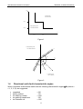
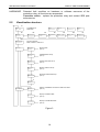
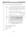
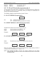
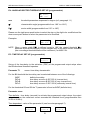
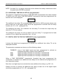
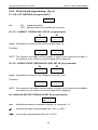
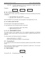
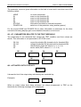
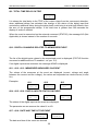
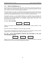
DIVISIONE ELETTRONICA E SISTEMI IAD3N DIGITAL DIRECTIONAL EARTH FAULT OR DIRECTIONAL POWER RELAY USER MANUAL P500D806 October 2007 SEB Divisione Elettronica e Sistemi INDEX INDEX 1 2 3 4 5 6 7 8 9 GENERAL CHARACTERISTICS..................................................................................1 1.1 Directional thresholds ............................................................................................3 1.2 Directional earth-fault - 3 independent thresholds .................................................5 1.3 Directional earth-fault with non-operating zone around the origin .........................5 1.4 Directional earth-fault characteristic angles ...........................................................6 1.5 Directional overcurrent or power detection (ANSI 67-32) ......................................7 FRONT PANEL KEYS ..................................................................................................8 FRONT PANEL LED SIGNALING ................................................................................9 PROGRAMMING AND TEST .....................................................................................10 4.1 How to program the protection relay....................................................................10 4.2 How to modify a visualized parameter.................................................................11 4.3 Reset ...................................................................................................................11 4.4 Test of output relays ............................................................................................12 DISPLAY AND PROGRAMMING ...............................................................................13 5.1 Standard display..................................................................................................13 5.2 Visualization structure .........................................................................................14 5.3 Address and time (fig. 3) .....................................................................................17 5.4 Function selection (fig. 3) ....................................................................................18 5.5 Nominal values set-up (fig. 4) ..............................................................................18 5.6 Thresholds and time delays set-up (fig. 4)...........................................................19 5.6.1 S1, S2 and S3 thresholds programming (fig. 4)............................................20 5.6.2 SA threshold programming - (fig. 4) .............................................................23 5.7 Output relays programming (fig. 4) ......................................................................25 5.8 Digital inputs function programming (fig. 4) .........................................................26 5.9 Special function - voltage memory function (fig. 4) ..............................................27 5.10 Parameter values visualization (fig. 5).................................................................27 5.11 Events (fig. 5) ......................................................................................................28 5.12 TRIPS COUNTERS (fig. 5)..................................................................................31 INSTALLATION ..........................................................................................................32 6.1 Supplied kit ..........................................................................................................32 6.2 Cabling ................................................................................................................33 6.3 Relays R3 and R4 - Signaling / Command set-up ...............................................37 6.4 RS485 serial communication port........................................................................37 TIME DEPENDENT CURVES ....................................................................................39 TECHNICAL CHARACTERISTICS.............................................................................40 TABLES......................................................................................................................42 Information printed in this manual subject to change without prior notice. This manual must not be reproduced in whole or in part, in any form or by any means without the express written permission of SEB Divisione Elettronica e Sistemi. SEB Divisione Elettronica e Sistemi 1 GENERAL CHARACTERISTICS GENERAL CHARACTERISTICS The protection relay IAD3N is designed to perform one of the following functions: Function Directional earth fault Directional overcurrent and directional power detection (active or reactive) ANSI Measures 67N Io, Vo 67 - 32 I1, V23 The IAD3N relay as directional earth fault relay is used in electrical systems with: • • • • • unearthed neutral neutral solidly earthed neutral earthed through a resistor neutral earthed through transformer neutral earthed through Petersen coil All the set-up and measured parameters can be visualized on the front panel display and transmitted on the RS485 communication serial port. THRESHOLDS - the IAD3N relay manages up to 3 independent directional thresholds (S1, S2 and S3); each threshold is defined by the following programmable information: • • • current threshold Is> voltage threshold Us> characteristic angle and sector width The directional earth-fault function can be selected as: • • 3 INDEPEDENT DIRECTIONAL thresholds DIRECTIONAL with NON operating zone around the origin (see fig. 1) The available settings for each threshold are listed in Table A; the operation of the directional thresholds is described in paragraph 1.1. TRIP DELAYS - a programmable time delay (TI) is available for each threshold; the first threshold (S1) can be programmed as time definite or time dependent in compliance with IEC 255-4 standard. For each threshold programmed as definite time, an additional programmable time delay (TA) is available; the additional time delay is added to time delay TI. The additional time delay activation is controlled by the digital inputs to allow the use of the IAD3N relay with cooperating protection relays. The available settings for each time delay are listed in Table A. OUTPUT RELAYS - the IAD3N controls 4 output relays (named R1, R2, R3 and R4); these relays can be programmed to be activated on START or TRIP conditions of one or more thresholds. 1 SEB Divisione Elettronica e Sistemi GENERAL CHARACTERISTICS START instantaneous activation of the output relay when electrical parameters exceed the programmed threshold values. TRIP activation of the output relay when the programmed time delay (TI or TI+TA) related to a threshold expires. The quiescent state of each single relay R1, R2, R3 and R4 can be programmed as normally energized (ON) or normally de-energized (OFF). An additional relay R5 (normally energized) is controlled by the self-diagnosis routines to report detected fault conditions. Related to each threshold, partial and total counters of TRIP conditions are available. DIGITAL INPUTS - there are available 3 digital inputs to activate the following functions (when enabled by the programmed set-up): • additional time delay (related to one or more thresholds) • on/off thresholds • STATUS function (recording of measures on external event) • pilot wire fault monitoring (only DIG2) For each digital input can be programmed the condition that activates the related functions: HI voltage = LO voltage = > 20 V dc / ac 0 ÷ 10 V dc / ac The digital input acquisition is valid when the voltage value stays in the range HI or LO for at least 40 ms. DISPLAY OF MEASURES - the user can select the continuous display of a measured parameter (current, voltage, phase); all the measured and computed parameters can be transmitted to an external controller through the RS485 port. EVENTS - information related to the last 8 events (TRIP or STATUS) are recorded in the EEPROM memory. Information includes the threshold set-up and activated relays (TRIP event only), the measured current, voltage, phase, the digital input status, date and time of the event. SELF-DIAGNOSIS - the software includes a non stop monitoring module that controls the functionality of all hardware and software resources of the protection relay. Detected fault conditions are reported by: • diagnostic message on the display • glow of a red LED on front panel 2 SEB Divisione Elettronica e Sistemi • GENERAL CHARACTERISTICS R5 output relay drop-off The fault condition signaling stays until faults are pointed out by the monitoring module; during this condition the protection functions are suspended to avoid unsuitable tripping. STATUS FUNCTION - when the STATUS function is activated by one of the digital input (when programmed) the protection relay memorizes information related to measured parameters and digital input status (see par. 5.11 - EVENTS). The recorded information allows an analysis of trip causes in co-operative protection relays systems. PILOT WIRE FAULT MONITORING - when the function is programmed, the digital input DIG2 is used to control the correct functionality of the pilot wire. Digital input DIG2 is always expected to be complementary of DIG1 input (HI-LO or LO-HI) to identify faults on pilot wire. The fault condition is reported as detected by the self-diagnosis module but the protection functions are not suspended; only the functions related to DIG1 digital input are suspended as the DIG1 status cannot be longer considered as true. The fault condition is reported when DIG1 and DIG2 signals are not complementary for more then 100 ms. REMOTE COMMUNICATION - the opto-insulated serial port RS485 can communicate with a personal computer or a remote control and monitoring system equipped with an RS485 interface or with a standard RS485/RS232 converter. It is possible to select the communication standard between STANDARD (ASCII 7 bit Seb protocol) or MODBUS (ASCII mode, SLAVE). All the set-up and measured parameters can be transmitted on the RS485 communication serial port; when communication is active (LED REMOTE glows), the operator on front panel can view the relay set-up but changes of parameters are disabled (ENTER and buttons disabled). VOLTAGE MEMORY FUNCTION - when the relay is working as directional power relay (ANSI 67-32) the VOLTAGE MEMORY function can be programmed by the operator. When the function is active, if a close fault condition occurs and the reference voltage suddenly drops to very small values (lower than the threshold Us> related to the directional overcurrent thresholds S1, S2, S3) the protection relay keeps for 500 ms a memorized reference voltage corresponding to the system voltage prior to the fault and thus the relay can operate properly. The memorized reference voltage is related to system frequency before the incidence of the fault. 1.1 Directional thresholds The IAD3N protection relay measures a voltage, a current and computes the phase angle between the voltage (reference - Vo or V23) and the current (Io or I1). The nominal current and voltage are programmable; two current inputs are available (1 A and 5 A) to match the nominal current of plant CT. 3 SEB Divisione Elettronica e Sistemi GENERAL CHARACTERISTICS Three independent directional thresholds S1, S2 and S3 are available; each threshold is defined by the following parameters: Isx> Usx> Φsx< overcurrent threshold overvoltage threshold angular sector threshold ANGULAR SECTOR THRESHOLD - the threshold is defined by the following parameters: Φx characteristic angle (e.g.: Φ1 related to directional threshold S1) DΦx sector width (e.g.: DΦ1 related to directional threshold S1) Characteristic angle - The characteristic angle is defined with the measured voltage as reference (straight line C in figure 2). The characteristic angle can be programmed from +180° to -180° and it is shown using the notation Φx. The angle Φx of the sector axis is positive when lagging the voltage vector (see figure 2). Sector width - the sector width is symmetrically defined referred to the straight line C. The sector width can be programmed from +15° to +180° and it is shown using the notation DΦx. DIRECTIONAL THRESHOLD OPERATION - The directional threshold S1 operates when the following conditions are verified: • the measured current is greater than the threshold Is1> • the measured voltage is greater than the threshold Us1> • the measured current phasor is within the sector defined by the parameter Φ1 and DΦ1 therefore if the following characteristic angle is programmed: Φ1 = +90° DΦ1 = 15° the directional threshold will operate if the angle of the measured current phasor is lagging the voltage phasor from +75° to +105° (+90° ± 15°). For the available settings of the thresholds Isx>, Usx> and of the parameters Φx and DΦx please refer to Table A. NON DIRECTIONAL THRESHOLDS - When the sector width DΦx is defined equal to 180° the threshold becomes non-directional and the voltage threshold is indifferent (only the modules of the measured currents are taken into consideration by the protection relay). This functionality allows the programming of additional non-directional thresholds to obtain a higher degree of protection. 4 SEB Divisione Elettronica e Sistemi GENERAL CHARACTERISTICS Every threshold can be programmed ON / OFF or disabled with an external command through digital inputs. 1.2 Directional earth-fault - 3 independent thresholds The 3 independent directional earth-fault thresholds are defined by the followings: threshold S1 - Is1>, Us1>, Φs1< threshold S2 - Is2>, Us2>, Φs2< threshold S3 - Is3>, Us3>, Φs3< (parameters DΦ1 and Φ1) (parameters DΦ2 and Φ2) (parameters DΦ3 and Φ3) Each current threshold Isx>, voltage threshold Usx> and each angular sector (characteristic angle Φx and sector width DΦx) is independently programmable; the threshold S1 can be programmed as definite time or dependent time, whilst the remaining thresholds are time definite only (see curves paragraph 7). Each threshold S1, S2 and S3 can be activated or disabled by the user. The protection operates on the directional threshold Sx if AT THE SAME TIME the measured current and voltage are greater than the thresholds Isx> and Usx> and if the current phasor is in the angular sector Φsx< defined as Φx ± DΦx (with the measured voltage as reference). The available settings for each time delay are listed in Table A 1.3 Directional earth-fault with non-operating zone around the origin The thresholds S1 and S2 (current thresholds Is1> and Is2> and voltage thresholds Us1> and Us2>) are logically combined (OR) to obtain the threshold SA and they allow you to have an operating voltage-current characteristic as showed in figure 1 (for any angular sector ΦA<); this characteristic allows very low voltage and current thresholds with a NON operating zone around the origin; the threshold S3 remains independent. The threshold SA has only one angular sector threshold ΦA< defined by the parameters ΦA and DΦA. That is: SA → logical OR threshold S1 → Is1>, Us1> threshold S2 → Is2>, Us2> angular sector threshold ΦA< = ΦA ± DΦA The constraints on the current and voltage thresholds are the followings: Is1> ≤ Is2> Us1> ≥ Us2> These constraints are verified by the protection relay during the set-up and an error message will be displayed if required. The S3 threshold operates normally with the parameters Is3>, Us3> and Φs3<. 5 SEB Divisione Elettronica e Sistemi GENERAL CHARACTERISTICS Uo operating area zona intervento Us1 > NON operating area zona NON intervento Us2 > Io Is1 > Is2 > Figure 1 I > NON operating area zona NON intervento X Dø U ø Dø I C I > operating area zona intervento Figure 2 1.4 Directional earth-fault characteristic angles When it operates as directional earth-fault the following characteristic angles ΦSx (where x = 1, 2, 3, A) are suggested: • • • • • unearthed solidly earthed via earthing resistor via earthing transformer via Petersen coil + 90° - 75° + 180° - 90° + 180° 6 SEB Divisione Elettronica e Sistemi GENERAL CHARACTERISTICS The suggested sector width DΦx in the first 4 cases is 85°. With unearthed systems the threshold S3 could be programmed with -90° characteristic angle to be used as reserve function against earth faults on different lines. With solidly earthed system it is suggested to use the phase overcurrent threshold ANSI 67. 1.5 Directional overcurrent or power detection (ANSI 67-32) There are available 3 directional overcurrent independent thresholds defined by the following current and voltage thresholds and angular threshold parameters: threshold S1 - Is1>, Us1>, Φs1< threshold S2 - Is2>, Us2>, Φs2< threshold S3 - Is3>, Us3>, Φs3< (parameter DΦ1 and Φ1) (parameter DΦ2 and Φ2) (parameter DΦ3 and Φ3) Each current threshold Isx> and each angular sector (characteristic angle Φx and sector width DΦx) is independently programmable; the voltage thresholds Us2> and Us3> are equal to Us1>. The threshold S1 can be programmed as definite time or dependent time, whilst the remaining thresholds are time definite only (see curves paragraph 7). The insertion diagram is presented in figure 7; the IAD3N relay is a single-phase relay therefore it can be used in system assumed to be balanced (generators). The current and the voltage must be applied as following (cross polarization): Current Ir Current Is Current It Voltage U s-t Voltage U t-r Voltage U r-s The following characteristic angles are suggested, as presented in figure 8: Directional active power Directional reactive power -90° 0° With these angles set-up the IAD3N relay will operate when the active or reactive power is negative. It is available a VOLTAGE MEMORY FUNCTION. When the function is active, if a close fault condition occurs and the reference voltage suddenly drops to very small values (lower than the threshold Us1> related to the directional overcurrent thresholds S1, S2, S3) the protection relay keeps for 500 ms a memorized reference voltage corresponding to the system voltage prior to the fault and thus the relay can operate properly. The memorized reference voltage is related to system frequency before the incidence of the fault. 7 SEB Divisione Elettronica e Sistemi 2 FRONT PANEL KEYS FRONT PANEL KEYS The 5 push-buttons on the front panel allow to visualize all the protection parameters and to modify the protection set-up. right arrow down arrow ENTER programming session activation or parameter confirmation change or increment of the selected parameter RESET reset of the protection relay (ref. Par. 4.3) VISUALIZATION OF PARAMETERS • all visualizations are circular and they can be displayed using the two arrow pushbuttons. • the structure of the visualizations and their contents are showed in Fig. 3, 4 and 5. • when the sealable transparent front panel is installed only the arrow push-buttons and the RESET push-button are accessible to prevent unauthorized modification of the protection set-up. MODIFICATION OF PARAMETERS • remove the transparent sealable front panel to access [ENTER] and buttons. 8 push- SEB Divisione Elettronica e Sistemi 3 FRONT PANEL LED SIGNALING FRONT PANEL LED SIGNALING POWER (green) ⊗ auxiliary supply available FAIL (red) ⊗ fault condition detected by SELF-DIAGNOSIS software or by PILOT WIRE FAULT MONITORING function REMOTE (red) ⊗ communication session active on RS485 port S1 SA (red) ⊗ trip condition on S1 or SA thresholds S2 SA (red) ⊗ trip condition on S2 or SA thresholds S3 (red) ⊗ trip condition on S3 threshold The last trip condition (threshold indication) is also showed on front panel display; more information on trip condition are presented in the recorded EVENT (see par. 5.11). 9 SEB Divisione Elettronica e Sistemi 4 PROGRAMMING AND TEST PROGRAMMING AND TEST The protection relay is easily programmable following the instructions in the next paragraphs: • • HOW TO PROGRAM THE PROTECTION RELAY HOW TO MODIFY A VISUALIZED PARAMETER All parameters can be freely modified; the proper protection set- up as required by the plant management is submitted to the operator's judgment. 4.1 How to program the protection relay The programmable parameters are showed in Figures 3, 4 and 5 at the following references: B2÷B7 C1 D1÷D6 E1÷E9 F1÷F6 G1÷G3 H1 R1÷R11 relay address (RS485) and date/time protection function nominal values, contrast etc. thresholds and time delays output relays functions digital input functions voltage memory partial trip counters reset The programming sequence is the following: 1) SELECT the visualization (on display) of the parameter to be modified using the arrow push-buttons 2) ACTIVATE the PARAMETER MODIFICATION session depressing the [ENTER] push-button and modify the parameter value 3) END the parameter modification session depressing again the [ENTER] pushbutton 4) REPEAT the procedure from 1) to 3) for all the parameters required to obtain the new protection relay set-up 5) CONFIRM the new protection relay set-up at the visualization CONFIRM PROG? (Fig. 3, ref. J1) within 5 minutes depressing the push-buttons [ENTER] and up to visualize YES and [ENTER] again to confirm. NOTE: The protection relay continues to operate using the previous set-up until the new set-up is confirmed as at point 5) above; the visualization of the modified parameters before the new set-up confirmation is only temporary to allow an easy definition of the new protection set-up. If the new set-up is not confirmed within 5 minutes from the last pressed push-button, the protection relay visualizes again the previous set-up (the parameters set-up that the protection relay is still using). 10 SEB Divisione Elettronica e Sistemi 4.2 PROGRAMMING AND TEST How to modify a visualized parameter When the parameter to be modified is visualized on front panel display do the following sequence: 1) PRESS [ENTER] to activate the parameter modification session If one or more parameters are modifiable, on the first of them will appear a blinking cursor. If no parameters are modifiable, no blinking cursor will appear. 2) MODIFY THE PARAMETER pressing the arrow push-buttons and when two parameters are modifiable, the push-button allows to point-out the parameter to be modified (the selected parameter will blink) when numerical parameters are pointed-out the push-button allows to select the digit to be modified increasing of the parameter 3) a) the digits are increased by 1 unit b) the other parameters are presented following the selection list PRESS [ENTER] to end parameter modification session The modification session is ended and the parameter stops to blink NOTE: if a numerical parameter is selected out of the accepted range (as shown in Table A) when the push-button [ENTER] is pressed for few seconds an error message will be displayed as: Data Error and the parameter will be displayed again with the former value. 4.3 Reset When the push-button [RESET] is pressed, the protection relays returns to the standard condition: • reset of glowing LED’s • drop-off of tripped relays • reset of any parameter changed but not confirmed (parameters are shown as confirmed at the end of the last programming session) 11 SEB Divisione Elettronica e Sistemi • 4.4 PROGRAMMING AND TEST display on STANDARD MODE (Fig. 3, ref. A1 – par. 5.1) Test of output relays When the output relays test is selected (Fig. 4, ref. F6) it is possible to command an output relay (one at the time) to trip from the current status allowing functional tests on electrical plants. The output relays are activated with the following sequence: 1) SELECT THE VISUALIZATION of the desired output relay to be tested TEST R1 OFF 2) PRESS [ENTER] to activate the test session; the message OFF will start to blink. 3) PRESS and the message on the display will change as: TEST R1 ON 4) PRESS [ENTER] to command the instantaneous trip of the output relay (change of the current status). The relay will stay on the new condition until: • the • the [ENTER] push-button is pressed and the sequence at points 3 and 4 is repeated (presenting OFF condition) or [RESET] push-button is pressed The same procedure will be used for R2, R3 and R4 relays. 12 SEB Divisione Elettronica e Sistemi 5 DISPLAY AND PROGRAMMING DISPLAY AND PROGRAMMING The contents and the structure of the displayed messages are shown in figures 3, 4 and 5; the references A1, B1, B2 etc. identify specific displayed messages in the figures. 5.1 Standard display A1 - STANDARD DISPLAY (fig. 3) It is the standard displayed message without operator's intervention (no push-buttons pressed for at least 5 minutes) or when the RESET push-button has been pressed. The displayed information is function of the protection relay status. NORMAL FUNCTIONING During this state the following information can be visualized (as defined by set-up): • Protection function (ANSI code) - the display shows the ANSI codes of the main selectable functions (ref. C1 - FUNCTION SELECTION). • Measured parameters - the display shows one of the measures (current, voltage, angle). The measure is visualized as primary values. ON TRIP CONDITION When a trip condition occurs the protection relay visualizes the TRIP message that includes the threshold related to the trip; the displayed messages are as the following: TRIP S1 TRIP S2 TRIP S3 TRIP SA The information of the trip, as well the glowing of the related LED’s, is displayed until the [RESET]. push-button is pressed. If a new trip condition occurs, the displayed information will be updated; information related to previous trips are recorded in EVENTS memory. FAULT CONDITION When a permanent or temporary fault condition is detected by the self-diagnosis module, the following message will be displayed: FAIL eeeeeeee The string eeeeeeee can be: F.PILOT Detected fault condition on pilot wire; the function related to DIG1 digital input is suspended Corrective action - verify pilot wire (short or open circuit) 13 SEB Divisione Elettronica e Sistemi HARDWARE 5.2 DISPLAY AND PROGRAMMING Detected fault condition on hardware or software resources of the protection relay; all functions are suspended. Corrective action - replace the protection relay and contact SEB post sales service Visualization structure A1 ANSI XX XXX B1 UAR4N mod T4 C1 FUNCTION aaaaaaaa SET-UP ALTERNATIVE DISPLAYS B2 PROTOCOL yyyyyyyy B3 BAUDRATE nnnn FAIL eeeeeeee TRIP S1 V xxxxxx V ANGLE nnn° B4 NR RELAY xxx B5 SER. NR. zzzzzzzz B6 VERS SW zz.zz B7 dd/mm/yy hh:mm:ss Function selection MAX I, EARTH 1, EARTH 2 NOMINAL VALUES Nominal data (FIG. 4) THRESHOL SET-UP THRESHOLDS set-up (FIG. 4) RELAYS FUNCTION OUTPUT RELAYS set-up (FIG. 4) DIGITAL INPUT DIGITAL INPUTS set-up (FIG. 4) SPECIAL FUNCTION SPECIAL FUNCTION set-up (FIG. 4) J1 CONFIRM PROG?.. MEASURES & EVENTS SIGNAL STATUS Display of SIGNALS and OUTPUT RELAYS status (FIG. 5) EVENTS Display of EVENTS data (FIG. 5) COUNTERS Display of COUNTERS data (FIG. 5) Figure 3 14 SEB Divisione Elettronica e Sistemi From FIGURE 3 SET-UP D1 NOMINAL VALUES In=j A DISPLAY AND PROGRAMMING D2 Un= xxx.xx V D3 I prim yyyyy A D4 V prim xxxxxx V D5 DISPLAY eeeeeeee D6 CONTRAST LEV n S1 and S2 thresholds are present only when I MAX or EARTH 1 function is selected THRESHOL SET-UP S1 E1 ccc E2 Is1> nn.nn In E3 Us1> n.nnn Un E4 1 nnn° D 1 nnn° E5 TI eeeee xx.xx s E6 TA S1 xx.xx s E7 TA S1 eeeeeeee S2 ccc Is2> nn.nn In Us2> n.nnn Un 2 nnn° D 2 nnn° TI eeeee xx.xx s TA S2 xx.xx s TA S2 eeeeeeee SA threshold is present only when EARTH2 function is selected SA E1 ccc E2 IA1> nn.nn In E3 IA2> nn.nn In E4 UA1> n.nnn Un E5 UA2> n.nnn Un E6 A nnn° D A nnn° E7 TI eeeee xx.xx s E9 TA SA eeeeeeee E8 TA SA xx.xx s TA S3 eeeeeeee S3 threshold always present S3 RELAYS FUNCTION ccc Is3> nn.nn In Us3> n.nnn Un 3 nnn° D 3 nnn° TI eeeee xx.xx s TA S3 xx.xx s F1 R1 NORM ccc F2 R1 S1 xxxxxxxx F3 R1 S2 xxxxxxxx F4 R1 SA xxxxxxxx F5 R1 S3 xxxxxxxx F6 TEST R1 yyyyyyyy R2 NORM ccc R2 S1 xxxxxxxx R2 S2 xxxxxxxx R2 SA xxxxxxxx R2 S3 xxxxxxxx TEST R2 yyyyyyyy R3 NORM ccc R3 S1 xxxxxxxx R3 S2 xxxxxxxx R3 SA xxxxxxxx R3 S3 xxxxxxxx TEST R3 yyyyyyyy R4 NORM ccc R4 S1 xxxxxxxx R4 S2 xxxxxxxx R4 SA xxxxxxxx R4 S3 xxxxxxxx TEST R4 yyyyyyyy present only with I MAX & EARTH 1 DIGITAL INPUT G1 DIG1 cc xxxxxxxx SPECIAL FUNCTION H1 MEMORIA TENS. xX G2 DIG2 cc xxxxxxxx G3 DIG3 cc xxxxxxxx J1 CONFIRM PROG?.. To FIGURE 5 Figure 4 15 present only with EARTH2 selected always present From FIGURE 4 MEASURES & EVENTS COUNTERS EVENTS SIGNALS STATUS 16 R1 S1 P eeee R2 S1 T eeee Q2 E1 IXx> nn.nn In Q1 E1 cccccccc E8 aaaaaaaa P2 U=x.xxx yyyyyy V P1 I=xx.xx yyyyy A MEASURES STATUS R3 S2 P eeee Q11 E1 I yy.yy In Q3 E1 UXx> nn.nn Un N2 DIG3 ww N1 DIG1 ww DIG2 ww DIGITAL STATUS M2 R3 ccc R4 ccc M1 L2 R1 ccc R2 ccc S2 status RELAYS STATUS L1 S1 status THRESHOL STATUS P3 L3 L4 R5 S3 P eeee Q13 E1 ANG zzz° Q5 E1 UAx> nn.nn Un S3 status Figure 5 R4 S2 T eeee Q12 E1 V yy.yy Un Q4 E1 IAx> nn.nn In ANGLE nnn° SA status Q6 R6 S3 T eeee Q14 E1 DIG1 ww E1 x nnn° R7 SA P eeee Q15 E1 DIG2 ww Q7 E1 D x nnn° R8 SA T eeee Q16 E1 DIG3 ww Q8 E1 RELE i,j,k R9 TOT PRG cccc Q17 E1 Date gg/mm/aa Q9 E1 T-Tot ww.ww s R10 DATE PGR dd/mm/yy Q18 E1 Time hh:mm:ss Q10 E1 DIG nnnnnnnn R11 TIME PRG hh:mm:ss SEB Divisione Elettronica e Sistemi DISPLAY AND PROGRAMMING SEB Divisione Elettronica e Sistemi 5.3 DISPLAY AND PROGRAMMING Address and time (fig. 3) B1 - RELAY MODEL (not programmable) IAD3N The same protection relay can be used with CT’s rated 1 A or 5 A. B2 - COMMUNICATION PROTOCOL (programmable) B2 PROTOCOL xxxxxxxx The communication protocol is programmable between the followings: STANDARD ASCII Seb protocol MODBUS Modbus protocol (SLAVE) When the MODBUS protocol is selected the following display is showed to allow the selection of the transmission speed: B3 BAUDRATE xxxx The xxxx parameter is selectable between the followings: 300 - 600 - 1200 - 2400 - 4800 - 9600 When the STANDARD protocol is selected the baud rate is automatically selected by the protection relay. B4 - ADDRESS (programmable) NR RELAY 001 Programmable address from 001 to 255. The number is used on RS485 port to address a specific relay when two or more protection relays are linked on the same serial line. B5 - RELAY SERIAL NUMBER (not programmable) SER. NR 0012345 B6 - SOFTWARE REVISION LEVEL (not programmable) SW REV zz.zz 17 SEB Divisione Elettronica e Sistemi DISPLAY AND PROGRAMMING B7 - TIME / DATE (programmable) dd/mm/yy hh:mm:ss Time and date are programmable and they are used to mark recorded events. NOTE the clock is not provided with back-up battery, therefore a loss of auxiliary supply will force time/date to the following condition: 01/01/90 00:00:00 5.4 Function selection (fig. 3) C1 - FUNCTION SELECTION (programmable) FUNCTION xxxxxxxx The function selection defines the available thresholds. FUNCTION Directional earth-fault independent thresholds Directional earth-fault operating zone with with Directional power relay 3 NON ANSI SELECTIONS THRESHOLDS 67N EARTH 1 S1, S2, S3 67N EARTH 2 SA, S3 67 - 32 MAX I S1, S2, S3 Examples: FUNCTION MAX I 5.5 FUNCTION EARTH 1 FUNCTION EARTH 2 Nominal values set-up (fig. 4) D1 - NOMINAL CURRENT SELECTION In (programmable) In = xA In: nominal phase current programmable 1 A or 5 A D2 - NOMINAL VOLTAGE SELECTION - Un (programmable) Un = xxx.xx V 18 SEB Divisione Elettronica e Sistemi Un: DISPLAY AND PROGRAMMING nominal voltage selection (nominal secondary voltage of plant VT) selectable between the followings: 57.73 - 63.50 - 72.16 - 100 - 110 - 125 - 190 - 220 - 230 - 380 - 400 D3 - PRIMARY CT’s CURRENT (programmable) I prim xxxxx A I prim: primary phase current value of the installed CT; it is programmable from 0001 to 18500 A. D4 - PRIMARY VT’s VOLTAGE (programmable) V prim xxxxxx V V prim: primary voltage value of the installed VT; it is programmable from 000001 to 999999 V. D5 - STANDARD DISPLAY SELECTION (programmable) DISPLAY eeeeeeee It allows to select the standard displayed information (ref. A1) when no trip condition occurs and no fault condition has been detected by the self-diagnosis module; the available selections are the following: ANSI CURRENT VOLTAGE ANGLE ANSI code of the available functions Measured current Measured voltage Measured angle between voltage and current Examples: DISPLAY ANSI DISPLAY CURRENT DISPLAY ANGLE D6 - DISPLAY CONTRAST LEVEL (programmable) CONTRAST LEV x The display contrast level is programmable from 0 to 9. The backlighted display is switched off if no push-button is pressed for at least 5 minutes; when one of the front panel push- button is pressed the display is switched on. 5.6 Thresholds and time delays set-up (fig. 4) Only the thresholds enabled at the FUNCTION SELECTION (ref. C1) are presented. Selection MAX I thresholds S1, S2, S3 19 SEB Divisione Elettronica e Sistemi Selection Selection EARTH 1 EARTH 2 DISPLAY AND PROGRAMMING thresholds S1, S2, S3 thresholds SA, S3 5.6.1 S1, S2 and S3 thresholds programming (fig. 4) The information and set-ups related to threshold S1 in the following points are effective for the thresholds S2 and S3 (if not specifically written) just taking into consideration the change of the threshold identification. The available settings for each threshold are listed in Table A. E1 - ON / OFF THRESHOLD (programmable) S1 ccc ccc ON - enabled threshold OFF - disabled threshold (available but not active) E2 - CURRENT THRESHOLD LEVEL SET-UP (programmable) Is1> nn.nn In Threshold level referred to the current nominal value (In) nn.nn n.nnn directional power relay (ANSI 67 - 32) directional earth fault (ANSI 67N) Examples: Is1> 01.50 In Is2> 02.00 In Is3> 0.500 In E3 - VOLTAGE THRESHOLD LEVEL SET-UP (programmable) Us1> n.nnn Un n.nnn threshold level referred to the voltage nominal value (Un) Examples: Us1> 0.050 Un Us2> 0.200 Un Us3> 1.000 Un When the measured voltage is lower than the threshold the voltage memory function (if enabled) will be activated (see par. 1. and par. 5.9). NOTE when selected the MAX I function (ref. function selection C1) the voltage thresholds Us2> and Us3> are equal to the programmed value Us1> and they are not programmable. 20 SEB Divisione Elettronica e Sistemi DISPLAY AND PROGRAMMING E4 - ANGOLAR SECTOR THRESHOLD SET-UP (programmable) Φ1 ±nnn° DΦ1 nnn° nnn threshold parameters expressed in degree (ref. paragraph 1.1) Φ1 characteristic angle (programmable from -180° to +180°) DΦ1 sector width (programmable from 015° to 180°) Please use the right arrow push-button to select the sign or the digit to be modified and the down arrow push-button to select the parameter to be modified. Examples: Φ1 +030° DΦ1 090° Φ2 -090° DΦ2 075° Φ3 +000° DΦ3 180° NOTE When a sector width DΦ1 is defined equal to 180° the related threshold Φ1< becomes NON-directional and it will be sensible only to the earth current threshold (the overvoltage threshold Us1> will be indifferent ) as ANSI 51N. E5 - TIME DELAY SET-UP (programmable) TI eeeee xx.xx s Set-up of the time-delay to the activation (TRIP) of the programmed output relays when the S1 directional threshold operates . Parameter TI eeeee: time delay characteristic For the S1 threshold the time delay can be selected between one of the followings: INDIP DIP=A DIP=B DIP=C definite time delay time delay as curve A IEC 255-4 (inverse time) time delay as curve B IEC 255-4 (very inverse time) time delay as curve C IEC 255-4 (extremely inverse time) For the thresholds S2 and S3 the TI parameter is fixed as INDIP (definite time). Parameter xx.xx: Time definite - time delay (seconds) to activate the programmed output relays: the output relay trips when the measured current exceeds the threshold level (programmable from 00.02 to 99.99 s). Time dependent - value of the parameter K (see formulas paragraph 7). TI DIP=B 02.50 K TI DIP=A 10.00 K 21 TI INDIP 03.25 s SEB Divisione Elettronica e Sistemi DISPLAY AND PROGRAMMING NOTE: the index K or s is shown coherently to the selected time-delay characteristic when the push-button ENTER is pressed. E6 - ADDITIONAL TIME DELAY SET-UP (programmable) The selection is displayed only when a TIME DEFINITE characteristic has been selected (TI INDIP at ref. E5); when TIME DEPENDENT characteristic has been programmed, the selection will not be displayed. TA S1 xx.xx s The additional time delay TA is programmable from 00.00 to 99.99 seconds; please note that at least one of the digital inputs should be programmed to activate the time delay function (ref. G1 ÷ G3 – paragraph 5.8). The additional time delay TA is added to the time delay TI to obtain the output relay trip when the TI+TA time expires. The additional time delay TA will be added if the time delay TI is programmed at least equals to 50 ms (digital input acquisition time - 40 ms) E7 - DIGITAL INPUT ACTIVE ON THRESHOLD (non programmable) TA S1 eeeeeeee It shows the digital input programmed to activate the additional time delay TA on the displayed threshold. The parameter eeeeeeee can show one of the following values: DISABLED none of the digital inputs has been programmed to activate an additional time delay related to the threshold S1 DIG1 digital input DIG1 activates the TA delay on threshold S1 DIG2 digital input DIG2 activates the TA delay on threshold S1 DIG3 digital input DIG3 activates the TA delay on threshold S1 When a TIME DEPENDENT characteristic threshold has been programmed the visualization is omitted as no additional time delays can be defined and programmed on time dependent delays. More than one digital input can activate the same additional time delay (e.g. DIG 1,3). Please note that to activate the additional time delay at least one of the digital inputs should be programmed (ref. G1 ÷ G3 - paragraph 5.8). 22 SEB Divisione Elettronica e Sistemi DISPLAY AND PROGRAMMING 5.6.2 SA threshold programming - (fig. 4) E1 - ON / OFF THRESHOLD (programmable) SA ccc ccc ON - enabled threshold OFF - disabled threshold (available but not active) E2 - E3 - CURRENT THRESHOLDS SET-UP (programmable) E2 IA1> n.nnn In E3 IA2> n.nnn In n.nnn threshold level referred to the current nominal value (In) Examples: IA1> 0.050 In IA2> 0.100 In NOTE The threshold level IA2> must be greater or equal to the threshold level IA1>; if the condition is not verified, an error message will be displayed. E4 - E5 - OVERVOLTAGE THRESHOLDS LEVEL SET-UP (programmable) E4 UA1> n.nnn Un E5 UA2> n.nnn Un n.nnn threshold level referred to the voltage nominal value (Un) Examples: UA1> 0.500 Un UA2> 0.100 Un NOTE The threshold level UA1> must be greater or equal to the threshold level UA2>;it the condition is not verified, an error message will be displayed. E6 - ANGOLAR SECTOR THRESHOLD SET-UP (programmable) ΦA ±nnn° DΦA nnn° nnn threshold parameters expressed in degree (ref. paragraph 1.1) ΦA characteristic angle (programmable from -180° to +180°) DΦA sector width (programmable from 015° to 180°) 23 SEB Divisione Elettronica e Sistemi DISPLAY AND PROGRAMMING Please use the right arrow push-button to select the sign or the digit to be modified and the down arrow push-button to select the parameter to be modified. Examples: ΦA +090° DΦA 090° NOTE: When a sector width DΦA is defined equal to 180° the related threshold SA becomes NON-directional and it will be sensible only to the earth current threshold (the overvoltage threshold UA> will be indifferent) as ANSI 51N. It is suggested to use as non-directional threshold the threshold S3 instead of the threshold SA. E7 - TIME DELAY SET-UP (programmable) TI INDIP xx.xx s Set-up of the time-delay to the activation (TRIP) of the programmed output relays when the SA directional threshold operates. Parameter xx.xx: time delay (seconds) to activate the programmed output relays: the output relay trips when the measured current exceeds the threshold level (programmable from 00.02 to 99.99 s). TI INDIP 01.50 s E8 - ADDITIONAL TIME DELAY SET-UP (programmable) TA SA xx.xx s The additional time delay TA is programmable from 00.00 to 99.99 seconds; please note that at least one of the digital inputs should be programmed to activate the time delay function (ref. G1, G2, G3 - paragraph 5.8). The additional time delay TA is added to the time delay TI to obtain the output relay trip when the TI+TA time expires. The additional time delay TA will be added if the time delay TI is programmed at least equals to 50 ms (digital input acquisition time - 40 ms) E9 - DIGITAL INPUT ACTIVE ON THRESHOLD (non programmable) TA SA xx.xx s It shows the digital input programmed to activate the additional time delay TA on the displayed threshold. The parameter eeeeeeee can show one of the following values: 24 SEB Divisione Elettronica e Sistemi DISPLAY AND PROGRAMMING DISABLED none of the digital inputs has been programmed to activate an additional time delay related to the threshold SA DIG1 digital input DIG1 activates the TA delay on threshold SA DIG2 digital input DIG2 activates the TA delay on threshold SA DIG3 digital input DIG3 activates the TA delay on threshold SA More than one digital input can activate the same additional time delay (e.g. DIG 1,3). Please note that to activate the additional time delay at least one of the digital inputs should be programmed (ref. G1, G2, G3 - paragraph 5.8). 5.7 Output relays programming (fig. 4) The session allows to program the activation of the output relays R1, R2, R3 or R4 on START or TRIP conditions for each threshold. In the programming session are displayed only the active thresholds depending on selections. Equivalent information and set-up related to relay R1 is available for the relays R2, R3 and R4 just changing the relay identification. F1 - OUTPUT RELAY R1 QUIESCENT STATUS (programmable) R1 NORM xxx Programming of the R1 relay status when no START or TRIP conditions are activated. NORM OFF: normally de-energized (energized status on activation) NORM ON: normally energized (de-energized status on activation) F2 - OUTPUT RELAY ACTIVATION ON THRESHOLD S1 (programmable) R1 S1 xxxxxxxx The parameter xxxxxxxx is selectable as the following: START TRIP NONE instantaneous output relay R1 activation when the threshold operates output relay R1 activation when the threshold is operating for at least TI or TI+TA seconds no activation related to threshold F3 ÷ F5 - OUTPUT RELAYS ACTIVATION ON THRESHOLDS S2, SA and S3 (programmable) Examples: R1 S2 xxxxxxxx R1 SA xxxxxxxx 25 R1 S3 xxxxxxxx SEB Divisione Elettronica e Sistemi DISPLAY AND PROGRAMMING Output relays activation on START or TRIP conditions related to S2, SA and S3 thresholds (as threshold S1 - ref. F2). F6 - TEST OF OUTPUT RELAYS R1 TEST R1 xxxxxxxx See paragraph 4.4 5.8 Digital inputs function programming (fig. 4) For each digital input one of the following functions are selectable: a) additional time delay (related to one or more thresholds - only time definite threshold) b) ON / OFF threshold (see paragraph 1.1) c) STATUS function (recording of measures on external command) d) pilot wire fault monitoring (only DIG2 monitors DIG1) When the function of more than one digital input refers to a threshold, the priority will be the following: a) OF selection (threshold disabled) has the priority on TA function (additional time delay) b) the ALL selection (ALL the thresholds) has the priority on single threshold selection. G1 - DIGITAL INPUT DIG1 SET-UP (programmable) DIG1 cc xxxxxxxx Programming of the function related to digital input channel 1 (DIG1). Parameter cc programming of the condition that activates the function related to digital input DIG1; the condition is selectable between HI and LO. Parameter xxxxxxx: programming of the function related to digital input DIG1; the following functions are selectable (only the active thresholds are presented - ref. E1): NONE TA S1 TA S2 TA S3 TA SA TA ALL OF S1 OF S2 OF S3 no functions active related to digital input DIG1 additional time delay on the threshold S1 additional time delay on the threshold S2 additional time delay on the threshold S3 additional time delay on the threshold SA additional time delay on all thresholds threshold S1 disabled threshold S2 disabled threshold S3 disabled 26 SEB Divisione Elettronica e Sistemi OF SA OF ALL STATUS DISPLAY AND PROGRAMMING threshold SA disabled all thresholds disabled activation of status function (see paragraph 1) G2 - DIGITAL INPUT DIG2 SET-UP (programmable) DIG2 cc xxxxxxxx Programming of the function related to digital input channel 2 (DIG2); the selections available are the same as presented for DIG1 (ref. G1) plus the following: MONITOR activation of pilot wire monitor function. G3 - DIGITAL INPUT DIG3 SET-UP (programmable) DIG3 cc xxxxxxxx Programming of the function related to digital input channel 3 (DIG3); the selections available are the same as presented for DIG1 (ref. G1). 5.9 Special function - voltage memory function (fig. 4) When the relay is working as directional power relay (ANSI 67-32 - function I MAX) the VOLTAGE MEMORY function can be programmed by the operator. When the function is active, if a close fault condition occurs and the reference voltage suddenly drops to very small values (lower than the threshold Us1> related to the directional overcurrent thresholds S1, S2, S3) the protection relay keeps for 500 ms a memorized reference voltage corresponding to the system voltage prior to the fault and thus the relay can operate properly. The memorized reference voltage is related to system frequency before the incidence of the fault. MEMORIA TENS.cc cc 5.10 ON - enabled function OFF - disabled function Parameter values visualization (fig. 5) L1 ÷ L4 - THRESHOLDS STATUS The actual status of each threshold is displayed; only the thresholds actionable as function of the FUNCTION SELECTION are presented. For each threshold are displayed the threshold identification (S1, SA etc.) and the threshold status; the status can show one of the following values: ON OFF active threshold disabled threshold (programmed OFF at ref. E1 - see par. 5.6) 27 SEB Divisione Elettronica e Sistemi OFF_DIG DISPLAY AND PROGRAMMING threshold programmed active but disabled by a digital input actual status (ref. G1 ÷ G3 see par. 5.8). Examples: S1 ON S2 ON SA OFF M1 - M2 - OUTPUT RELAY STATUS The actual status of each output relay is displayed; for each relay the following information is displayed: • • relay identification (R1, R2, R3, R4) relay status (ON - activated, OFF - non activated) Note that ON/OFF do not necessary mean energized or de-energized (see ref. G1). N1 - N2 - DIGITAL INPUT STATUS The actual status of each digital input is displayed. For each digital input the following information is presented: • • digital input identification (DIG1, DIG2, DIG3) digital input status (HI or LO) P1 - P2 - P3 - MEASUREMENT DISPLAY The actual values of the measures and of the computed parameters are displayed (currents, voltages, phase angles); the parameters related to disabled thresholds are not displayed. For each measure the following information is displayed: measure identification (I, V, ANGLE ) actual values expressed as Amperes, Volts and degrees 5.11 Events (fig. 5) On the display are shown the memorized information related to the last 8 TRIP or STATUS events. The 8 events are recorded and identified with a progressive number from 1 to 8; the more recent event shows a lower number. Q1 - EVENT NUMBER E1 cccccccc The index E1, E2 … E8 identifies the memorized event. 28 SEB Divisione Elettronica e Sistemi DISPLAY AND PROGRAMMING The parameter cccccccc gives information on the kind of event and it can show one of the following values: NONE S1 S2 S3 SA STATUS POWER ON no event memorized event on trip threshold S1 event on trip threshold S2 event on trip threshold S3 event on trip threshold SA information recorded on external command switch-on of the protection relay (auxiliary power) For the events NONE and POWER ON no other information is presented; for the other events the following displays give more detailed information on the event. Q2 - Q7 - PARAMETERS RELATED TO THE TRIP THRESHOLD The parameters of the threshold that caused the TRIP condition and their values are shown. This information is not presented on STATUS event. Q2, Q4 Q3, Q5 Q6 Q7 Q2 E1 IA1> y.yyy In current thresholds (Q4 showed only for threshold SA) voltage thresholds (Q5 showed only for threshold SA) characteristic angle (ΦX where X = 1, 2, 3, A) sector width (DΦX, where X = 1, 2, 3, A) Q3 E1 UA1> y.yyy Un Q4 E1 IA2> y.yyy In Q6 E1 ΦA +090° Q7 E1 Q5 E1 UA2> y.yyy Un DΦA 45° Q8 - ACTIVATED OUTPUT RELAYS E1 RELAY nnnnnnn It shows the list of the output relay activated by the threshold trip. Examples: E1 RELAY 1,3,4 E3 RELAY 1,4 When no output relays have been activated (no relays programmed to TRIP on the threshold) the following message will be displayed: E1 RELAY NONE 29 SEB Divisione Elettronica e Sistemi DISPLAY AND PROGRAMMING Q9 - TOTAL TIME DELAY ON TRIP E1 T-Tot www.ww s It is shown the total delay to the TRIP of the output relays from the overcurrent detection; when additional delays are activated, the change of the status of the digital input that controls the additional delay during the delay itself could bring to a total time different from the sum of the programmed delays. If the total time is greater than 999 seconds the display of tenths is omitted. When the event is memorized on the external command (STATUS), the message N/A (Not Applicable) is shown instead of the number of seconds. E1 T-Tot N/A Q10 - DIGITAL CHANNELS RELATED TO MEMORIZED EVENT E1 DIG 1, 3 The list of the digital inputs related to the memorized event is displayed (STATUS function command or additional time TA enabled - ref. par. 5.6). If no digital inputs were activated, the message NONE is displayed. Q11 - Q12 - Q13 - MEMORIZED MEASURES ON EVENT The values of the measures at the event are displayed (current, voltage and angle between the current and the voltage); the values are expressed as relative terms (In and Un). Examples: Q11 E3 I n.nnn In Q12 E3 U n.nnn Un Q13 E3 ANG nnn° Q14 - Q15 - Q16 - DIGITAL INPUTS STATUS ON EVENT E1 DIG1 vv E1 DIG2 vv E1 DIG3 The status of the digital inputs at the event are displayed. The parameter vv can assume the value HI or LO. Q17 - Q18 - DATE AND TIME OF THE EVENT E1 Date dd/mm/yy E1 Time hh:mm:ss The date and time of the event are showed 30 vv SEB Divisione Elettronica e Sistemi 5.12 DISPLAY AND PROGRAMMING TRIPS COUNTERS (fig. 5) In this section are displayed the total and partial counters of the output relay activation (on TRIP conditions) for each thresholds and the numbers of programming sessions with the date and time of the last confirmed programming session. The total counters, the number of confirmed programming sessions and the date and time of the last confirmed programming session are not modifiable or resettable; the information related to the last programming session are used to control unauthorized access. The partial counter can be modified following the standard set-up procedure for parameters as described at paragraph 4.2; the partial counters are immediately modified in the memory (the recorded values are immediately resetted without the need of the programming confirmation). R1 ÷ R8 - TRIP COUNTERS S1 P cccc S1 T cccc Display of the partial (P) and total (T) counters of the TRIP condition related to each threshold. When the value exceed 9999 the counter starts again from 0000. The counters are identified by the threshold name (S1, S2, S3 and SA); only the counter related to the active thresholds are shown (see selections to ref. C1). R9 ÷ R11 - TOTAL PROGRAMMING SESSIONS AND DATE/TIME OF THE LAST PROGRAMMING SESSION TOT PRG eeee DATE PRG dd/mm/yy TIME PRG hh:mm:ss Display of the number of confirmed programming sessions (from the factory set-up) and the date and time of the last confirmed programming session. 31 SEB Divisione Elettronica e Sistemi INSTALLATION 6 INSTALLATION 6.1 Supplied kit RK VERSION - 19" rack installation (the proper rack is supplied by Seb) • protection relay module IAD3N with rear socket • transparent front panel for rack installation • blister with items 1-2-3-4-5 CS VERSION - flush mounting installation • protection relay module IAD3N with rear socket • transparent front panel for rack flush mounting installation • n° 2 brackets for flush mounting • blister with items 1-2-3-4-5 • blister with item 6 1 2 3 6 4 5 Sacchetto BLISTER 1) n° 8 screws to fix wire terminals of current circuits 2) n° 4 screws to fix the relay rear socket on the 19" rack (or on the two brackets for flush mounting) and n° 2 screws to fix (optionally) the protection relay on the front of the 19" rack 3) n° 2 knobs to fix the transparent front panel 4) n° 8 washers to be used to fix current wire terminals 5) n° 8 growers to be used to fix current wire terminals 6) items to fix the brackets for flush mounting (only with CS version) The knobs to fix the transparent front panel must be screwed through the panel the front panel itself; the operation will create a screw thread in the plastic material and the knobs will never be missed. 32 SEB Divisione Elettronica e Sistemi 6.2 INSTALLATION Cabling Current circuits It is suggested to terminate the current wirings using eyelet terminals. Minimum suggested wire cross section: 2,5 mm2 With reference to the insertion diagram in the next page, the currents measured by the protection relay have the following matching: programmed nominal current In = 5A terminals A1 - A2 programmed nominal current In = 1A terminals B1 - B2 Voltage circuits It is suggested to terminate the voltage wirings using plug terminals. Minimum suggested wire cross section: 1,5 mm2 With reference to the insertion diagram in the next page, the voltages measured by the protection relay have the following matching: U terminals 11 - 13 voltages with Un programmed from 110 to 400 V terminals 12 - 13 voltages with Un programmed from 0 to 100 V Other circuits (output relays etc.) It is suggested to terminate the wiring using plug terminals. Minimum suggested wire cross section: 1,5 mm2 33 SEB Divisione Elettronica e Sistemi INSTALLATION Figure 6 - Directional earth fault insertion 34 SEB Divisione Elettronica e Sistemi INSTALLATION Figure 7 Figura 8 Directional power insertion 35 SEB Divisione Elettronica e Sistemi INSTALLATION 36 SEB Divisione Elettronica e Sistemi 6.3 INSTALLATION Relays R3 and R4 - Signaling / Command set-up The protection relay is supplied with R3 and R4 relays configured as SIGNALING RELAYS, with 2 change-over output contacts with breaking capability equals to 0.2 A at 110 Vdc, L/R = 40 ms, 100000 operations. Each R3 and R4 relay can be configured as COMMAND RELAY with 1 change-over output contact with breaking capability equals to 0.5 A at 110 Vdc, L/R = 40 ms, 100000 operations. The new configuration is obtained with the following cabling: R3 6.4 29 N.C. 28 27 N.O. 26 25 24 COM. 35 N.C. 34 33 N.O. 32 31 30 COM. R4 RS485 serial communication port The digital protection relay PQR4N presents an insulated serial interface RS485 halfduplex that allow the multi-drop connection up to 31 protection units. There are available 2 selectable communication protocols (ref. B2 paragraph 5.3). When the MODBUS communication protocol is selected, the transmission speed can be programmed between 300 to 9600 bauds (ref. B3, par. 5.3). When the STANDARD Seb communication protocol is selected, the transmission speed is automatically selected between 300 to 9600 bauds and the protocol is ASCII-HEX. It is suggested to use a shielded twisted pair AWG22; terminal 19 (not connected internally) can be used for shields connections. To integrate the protection relay in control systems, the documentation related to the protocol is freely available on request. 37 SEB Divisione Elettronica e Sistemi INSTALLATION Line H 120 Ohm Line L PROTEZ. 2 It is suggested to terminate the serial line with a resistance 120 Ω, 1/4 W. 38 PROTEZ. 3 23 21 20 23 22 21 20 23 22 21 20 PROTEZ. 1 22 120 Ohm CONTROLLORE SEB Divisione Elettronica e Sistemi 7 TIME DEPENDENT CURVES TIME DEPENDENT CURVES I / Is1> I / Is1> Time dependent characteristic t= I / Is1> 39 Ki ∗ K α I −1 Is1 > + 0.02s Curve IEC 255-4 A B C Ki 0.14 13.5 80 α 0.02 1 2 K Parameter 0.01 ÷ 20.00 s I / Is1> Ratio between the measured current and the threshold Is1> SEB Divisione Elettronica e Sistemi 8 TECHNICAL CHARACTERISTICS TECHNICAL CHARACTERISTICS Measuring inputs Rated phase current (In) Thermal withstand continuously Thermal withstand for 1 s Rated voltage (Un) programmable Thermal withstand continuously Thermal withstand for 1 s Rated frequency Primary CT’s current Primary VT’s voltage 1 A or 5 A 4 In 100 In 57,73 - 63,50 - 72,16 - 100 - 110 V 125 - 190 - 220 - 230 - 380 - 400 V 2 Un 2 Un 50 / 60 Hz 1 - 18500 A 1 - 999999 V Output contacts ratings Number of relays (note 1) Rated current Rated voltage Contact configuration Breaking capability (note 2) - tripping relays (R1, R2) - signaling relays (R3, R4, R5) (note 3) Mechanical life 4+1 5A 250 V change over 0.5 A 0.2 A > 106 Digital inputs Number of inputs External control voltage Typical current (sink) 3 as Uaux 2 mA Data transmission Standard Communication protocol Transmission speed Optional RS-485 half duplex MOD-BUS ASCII 300 - 9600 baud selectable fibre optic module Auxiliary supply Frequency (Vac) Burdens (min/max) 24 ÷ 320 Vdc ± 20% 48 ÷ 230 Vac ± 20% 47 ÷ 63 Hz 5 / 10 W Environmental conditions Operation Transport and storage Relative humidity (without condensation) Protection degree for flush mounting (optional) Weight - 10 / +60 °C - 25 / +80 °C < 95% IP 52 (IP 54) 2.5 kg Range Note 1) Note 2) The additional relay R5 is controlled by self-test program Breaking capability at 110 Vdc, L/R 40 ms, 100.000 operations 40 SEB Divisione Elettronica e Sistemi Note 3) TECHNICAL CHARACTERISTICS The output contacts of R3 and R4 relays can be configured as signaling or tripping relays 41 SEB Divisione Elettronica e Sistemi 9 TABLES TABLES Table A Thresholds and time delays DIRECTIONAL EARTH FAULT (ANSI 67N) DIRECTIONAL POWER RELAY (ANSI 67-32) ON / OFF 0.005 ÷ 9.999 In ON / OFF 0.01 ÷ 30.00 In 0.01 In 0.01 In 0.004 ÷ 1.200 Un 0.004 ÷ 1.200 Un 0.001 Un 0.001 Un -180° ÷ +180° -180° ÷ +180° 1° 1° +15° ÷ +180° +15° ÷ +180° 1° 1° 0.02 ÷ 99.99 s 0.02 ÷ 99.99 s Resolution 0.01 s 0.01 s Characteristic curves (IEC 255-4) A, B, C A, B, C 0.01 ÷ 20.00 s 0.01 s 0.01 ÷ 20.00 s 0.01 s 0.00 ÷ 99.99 s 0.00 ÷ 99.99 s THRESHOLDS Is> Setting Resolution Us> Setting Characteristic angle Setting Sector width Resolution Resolution Setting Resolution Time Delays Definite Time Dependent time Setting Characteristic constant Resolution Additional delay ≥ 0.95 Drop-off ratio Is>, Us> ≤ 3° Hysteresis of directional detection ≤ 30 ms Overshoot time Programmable for each threshold START / TRIP and normally ON / OFF Output relays R1, R2, R3, R4 42 43 44 SEB DIVISIONE ELETTRONICA E SISTEMI - UFFICIO COMMERCIALE Via Segantini, 5 - 20825 BARLASSINA (MB) - tel. +39 0362 5669.1 - fax +39 0362 556622 web site: www.seb-barlassina.it mail to: [email protected]