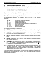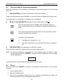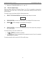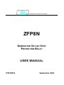
1
DIVISIONE ELETTRONICA E SISTEMI
ZFP8N
GENERATOR OUT-OF-STEP
PROTECTION RELAY
USER MANUAL
P501D810
September 2004
SEB Divisione Elettronica e Sistemi
INDEX
INDEX
1
2
3
4
5
6
7
8
GENERAL CHARACTERISTICS..................................................................................1
1.1
Threshold operations.............................................................................................3
FRONT PANEL KEYS ..................................................................................................7
FRONT PANEL LED SIGNALING ................................................................................8
PROGRAMMING AND TEST .......................................................................................9
4.1
How to program the protection relay......................................................................9
4.2
How to modify a visualized parameter.................................................................10
4.3
Reset ...................................................................................................................10
4.4
Test of output relays ............................................................................................11
DISPLAY AND PROGRAMMING ...............................................................................12
5.1
Standard display..................................................................................................12
5.2
Visualization structure .........................................................................................13
5.3
Address and time (figure 2) .................................................................................16
5.4
Protection insertion (figure 2) ..............................................................................17
5.5
Nominal values set-up (figure 3)..........................................................................17
5.6
Thresholds and time delays set-up (figure 3) ......................................................18
5.6.1
Out-of-step polygonal characteristic .............................................................18
5.6.2
Out-of-step function enabling thresholds ......................................................20
5.6.3
Voltage memory threshold............................................................................21
5.7
Output relays programming (figure 3)..................................................................22
5.8
Digital inputs function programming (figure 4) .....................................................24
5.9
Parameter values visualization (figure 4).............................................................25
5.10 Events (figure 4) ..................................................................................................26
5.11 Trip counters (figure 4) ........................................................................................29
INSTALLATION ..........................................................................................................30
6.1
Supplied kit ..........................................................................................................30
6.2
Cabling ................................................................................................................31
6.3
Relays R3 and R4 - Signaling / Command set-up ...............................................36
6.4
RS485 serial communication port........................................................................36
TECHNICAL DATA.....................................................................................................38
TABLES......................................................................................................................40
Information printed in this manual subject to change without prior notice.
This manual must not be reproduced in whole or in part, in any form or by any means
without the express written permission of SEB Divisione Elettronica e Sistemi.
SEB Divisione Elettronica e Sistemi
1
GENERAL CHARACTERISTICS
GENERAL CHARACTERISTICS
The protection relay ZFP8N is designed to perform the following functions:
Generator out-of-step protection
ANSI 78
The operation of the ZFP8N protection relay is based on the impedance measurement
method; the impedance vector is computed from the positive sequence components of the
measured voltages and currents; the protection relay verifies the absence of negative
sequence components of the currents and voltages and the absence of residual current.
The evolution of the measured impedance vector is checked on the X-R diagram with the
polygonal out-of-step characteristic to identify power swing occurrences.
When an out-of-step condition occurs, a timer is started and a counter is increased; during
the programmed time delay the protection relay will verify the number of out-of-step
occurrences and will increase the counter if any.
The protection relay will trip if the counter reaches the programmed maximum number of
allowed out-of-step occurrences in the time delay.
All the set-up and measured parameters can be visualized on the front panel display and
transmitted on the RS485 communication serial port.
THRESHOLDS - the ZFP8N protection relay manages the following independent
thresholds:
•
•
•
•
•
•
polygonal out-of-step characteristic (two zones with counters NZ1 and NZ2)
1 positive sequence minimum current threshold
I1<
1 negative sequence overcurrent threshold
I2>
1 negative sequence overvoltage threshold
U2>
1 residual overcurrent threshold
Ir>
1 undervoltage threshold (for voltage memory functionalities)
U<<
The available settings for each threshold are listed in Table A; the operation of the
protection relay is described in paragraph 1.1.
TIME DELAYS - programmable time delays related to the protection functions are
available; specifically the available time delays are the followings:
•
•
•
time length to check out-of-step occurrences (TLIM)
activation time of the output relay signaling the first out-of-step occurrence (TSIGN)
voltage memory duration (TMem)
All time delay are time definite; the available settings for each time delay are listed in Table
A
OUTPUT RELAYS - the ZFP8N controls 4 output relays (named R1, R2, R3 and R4);
these relays can be programmed to be activated on thresholds or functions.
1
SEB Divisione Elettronica e Sistemi
GENERAL CHARACTERISTICS
START
instantaneous activation of the output relay when the
parameter exceeds the programmed threshold value or
following function activation
TRIP
activation of the output relay when the programmed
maximum number of out-of-step occurrences is reached
for one of the two zones of the polygonal characteristics
(counters NZ1 and NZ2)
The quiescent state of each single relay R1, R2, R3 and R4 can be programmed as
normally energized (ON) or normally de-energized (OFF).
An additional relay R5 (normally energized) is controlled by the self-diagnosis routines to
report detected fault conditions.
Related to each counter, partial and total counters of TRIP conditions are available.
DIGITAL INPUTS - there are available 6 digital inputs to activate the following functions
(when enabled by the programmed set-up):
•
•
•
•
additional time delay on TLIM
on/off of one or more of the polygonal zones
STATUS function (recording of measures on external event)
pilot wire fault monitoring
For each digital input can be programmed the condition that activates the related
functions:
HI voltage =
LO voltage =
> 20V dc / ac
0 ÷ 10 V dc / ac
The digital input acquisition is valid when the voltage value stays in the range HI or LO for
at least 40 ms.
EVENTS - information related to the last 8 events (TRIP or STATUS) are recorded in the
EEPROM memory.
Information includes the thresholds set-up, the activated relays (TRIP event only), the
measured or computed parameters (measured currents and voltages, negative sequence
current and voltage), the digital input status and date and time of the event.
SELF-DIAGNOSIS - the software includes a non stop monitoring module that controls the
functionality of all hardware and software resources of the protection relay.
Detected fault conditions are reported by:
•
diagnostic message on the display
•
glow of a red LED on front panel
•
R5 output relay drop-off
2
SEB Divisione Elettronica e Sistemi
GENERAL CHARACTERISTICS
The fault condition signaling stays as far as faults are pointed out by the monitoring
module; during this condition the protection functions are suspended to avoid unsuitable
tripping.
STATUS FUNCTION - when the STATUS function is activated by one of the digital input
(when programmed) the protection relay memorizes information related to measured
parameters and digital input status (see par. 5.10 - EVENTS). The recorded information
allows an analysis of trip causes in co-operative protection relays systems.
PILOT WIRE FAULT MONITORING - when the function is programmed, the digital input
DIG2 is used to control the correct functionality of the pilot wire. Digital input DIG2 is
always expected to be complementary of DIG1 input (HI-LO or LO-HI) to identify faults on
pilot wire.
The fault condition is reported as detected by the self-diagnosis module but the protection
functions are not suspended; only the functions related to DIG1 digital input are
suspended as the DIG1 status cannot be longer considered as true.
When the function is activated, the fault condition will be detected when the status of DIG1
and DIG2 are equals for more then 100 ms.
REMOTE COMMUNICATION - the opto-insulated serial port RS485 can communicate
with a personal computer or a remote control and monitoring system equipped with an
RS485 interface or with a standard RS485/RS232 converter.
It is possible to select the communication standard between MODBUS (ASCII mode,
SLAVE) or STANDARD (ASCII 7-bit - SEB).
All the set-up and measured parameters can be transmitted on the RS485 communication
serial port; when communication is active (LED REMOTE glows), the operator on front
panel can visualize the relay set-up but changes of parameters are disabled (ENTER and
buttons disabled).
VOLTAGE MEMORY FUNCTION – power swings in the electrical network could cause,
on transient base, a very low voltage at protection measurement point.
The protection relay manages an undervoltage threshold (U<<) to detect this condition and
to start-up the voltage memory function; the voltage memory function will keep for a
programmed time length (Tmem, programmable up to 1 second) a voltage reference
corresponding to the system voltage prior to the fault and thus the relay will be able to
operate properly.
The memorized reference voltage is related to system frequency before the incidence of
the event.
When the Tmem time expires, the out-of-step protection functions will be disabled.
1.1
Threshold operations
The ZFP8N protection relay measures the currents and voltages of a generator and
computes:
3
SEB Divisione Elettronica e Sistemi
•
•
•
•
•
GENERAL CHARACTERISTICS
negative sequence current
negative sequence voltage
positive sequence current
positive sequence voltage
residual current
The positive sequence current component is verified with a programmable I1> threshold;
the out-of-step protection function will operate only if the threshold is exceeded.
The negative sequence voltage is verified with a programmable U2> threshold, whilst the
negative sequence current is verified with a programmable I2> threshold and the residual
current with the programmable Ir> threshold; the out-of-step protection function will be
disabled if one of the previous thresholds is exceeded.
These thresholds assure that the out-of-step protection operates under symmetrical
occurrences and not in presence of other electrical system failures to be detected by other
protection functions.
The positive sequence components of the voltages and the currents are used to compute
the impedance vector. The evolution of the impedance vector is checked on the diagram
X-R with the polygonal out-of-step characteristic.
The measurement characteristic of the protection relay is a polygonal represented by a
rectangle with programmable widths and inclination angle.
The inclination angle matches the centre points of the circles representing the locus of the
impedances seen from the measuring point (voltage transformers location) with out-of-step
occurrences.
The widths are defined as function of the impedance of the generator and of the unit
transformer.
The rectangle characteristic is defined by two zones:
Zone 1
covers the condition with the electrical centre of the power swings in
the generator and unit transformer
Zone 2
covers the condition with the electrical centre of the power swings in
the network system
The out-of-step condition is detected when the impedance vector enters the power swing
characteristic at one side and leaves it at the other side. This means a loss of synchronism
condition.
If the vector impedance enters and leaves the polygonal characteristic at the same side,
the power swing will evolve toward a stabilized condition.
When the impedance vector enters in the polygonal characteristic, the programmable timer
TLIM will start.
4
SEB Divisione Elettronica e Sistemi
GENERAL CHARACTERISTICS
For each characteristic’s zone a separate counter is defined (NZ1, NZ2) and each of them
is increased when the impedance vector enters and leaves the corresponding zone.
For each counter a maximum number of out-of-step conditions can be independently
programmed; when the corresponding counter reaches the programmed value, the
protection relay will trip.
If the programmed value of the counter is not reached within the programmed TLIM time
delay, the protection relay will reset (reset of NZ1 and NZ2 counters).
When the impedance vector enters in the polygonal characteristic for the first time, a
signaling output relay can be activated; the time length TSIGN of the output relay
activation is programmable.
Every out-of-step protection function can be programmed ON / OFF or disabled with an
external command through digital inputs
Insertion of the protection relay
At set-up level (ref. chapter 5.4, point C1) it is possible to select the protection relay
insertion as:
•
•
STAR
DELTA
operations measuring the phase to earth voltages
operations measuring the phase to phase voltages
Voltage memory function
Power swings in the electrical network could cause, on transient base, the presence of a
very low voltage where the measurement point.
The protection relay manages an undervoltage threshold (U<<) to detect this condition and
to start-up the voltage memory function; the voltage memory function will keep for a
programmed time length (Tmem, programmable up to 1 second) a voltage reference
corresponding to the system voltage prior to the fault and thus the relay will be able to
operate properly.
The memorized reference voltage is related to system frequency before the incidence of
the event.
When the Tmem time expires, the out-of-step protection functions will be disabled.
5
SEB Divisione Elettronica e Sistemi
GENERAL CHARACTERISTICS
Figure 1 - Polygonal Characteristic
6
SEB Divisione Elettronica e Sistemi
2
FRONT PANEL KEYS
FRONT PANEL KEYS
The 5 push-buttons on the front panel allow to visualize all the protection parameters and
to modify the protection set-up.
right arrow
down arrow
ENTER
programming session activation or parameter confirmation
change or increment of the selected parameter
RESET
reset of the protection relay (rif. par. 4.3)
VISUALIZATION OF PARAMETERS
•
all visualizations are circular and they can be displayed using the two arrow pushbuttons.
•
the structure of the visualizations and their contents are showed in figure from 2, 3
and 4.
•
when the sealable transparent front panel is installed only the arrow push-buttons
and the RESET push-button are accessible to prevent unauthorized modification of
the protection set-up.
MODIFICATION OF PARAMETERS
•
remove the transparent sealable front panel to access [ENTER] and
buttons.
7
push-
SEB Divisione Elettronica e Sistemi
3
FRONT PANEL LED SIGNALING
FRONT PANEL LED SIGNALING
POWER
(green)
⊗ auxiliary supply available
(red)
⊗ fault condition detected by SELF-DIAGNOSIS software or by PILOT
WIRE FAULT MONITORING function
REMOTE
⊗ communication session active on RS485 port
FAIL
(red)
PZ1
(red)
⊗ out-of-step ZONE 1
(counter NZ1)
(red)
⊗ out-of-step ZONE 2
(counter NZ2)
BLK
(red)
⊗ out-of-step disabled
(thresholds I2>, Ir>, U2>)
PZ2
The last trip condition (threshold indication) is also showed on front panel display; more
information on trip condition are presented in the recorded EVENT (see par. 5.10).
8
SEB Divisione Elettronica e Sistemi
4
PROGRAMMING AND TEST
PROGRAMMING AND TEST
The protection relay is easily programmable following the instructions in the next
paragraphs:
•
•
HOW TO PROGRAM THE PROTECTION RELAY
HOW TO MODIFY A VISUALIZED PARAMETER
All parameters can be freely modified; the proper protection set- up as required by the
plant management is submitted to the operator's judgment.
4.1
How to program the protection relay
The programmable parameters are showed in figures 2, 3 and 4 at the following
references:
B2 ÷ B7
C1
D1 ÷ D6
E1 ÷ E17
F1 ÷ F13
G1 ÷ G6
R1, R3, R5
relay address (RS485) and date/time
protection relay insertion
nominal values, contrast etc.
polygonal characteristic parameters, thresholds set-up
output relays functions
digital input functions
partial trip counters reset
The programming sequence is the following:
1)
SELECT the visualization (on display) of the parameter to be modified using the
arrow push-buttons
2)
ACTIVATE the PARAMETER MODIFICATION session depressing the [ENTER]
push-button and modify the parameter value
3)
END the parameter modification session depressing again the [ENTER] pushbutton
4)
REPEAT the procedure from 1) to 3) for all the parameters required to obtain the
new protection relay set-up
5)
CONFIRM the new protection relay set-up at the visualization CONFIRM PROG?
(Fig. 3, ref. J1) within 5 minutes depressing the push-buttons [ENTER] and
up
to visualize YES and [ENTER] again to confirm.
NOTE The protection relay continues to operate using the previous set-up until the new
set-up is confirmed as at point 5) above; the visualization of the modified
parameters before the new set-up confirmation is only temporary to allow an easy
definition of the new protection set-up.
If the new set-up is not confirmed within 5 minutes from the last pressed push-button, the
protection relay visualizes again the previous set-up (the parameters set-up that the
protection relay is still using).
9
SEB Divisione Elettronica e Sistemi
4.2
PROGRAMMING AND TEST
How to modify a visualized parameter
When the parameter to be modified is visualized on front panel display do the following
sequence:
1)
PRESS [ENTER] to activate the parameter modification session
If one or more parameters are modifiable, on the first of them will appear a blinking cursor.
If no parameters are modifiable, no blinking cursor will appear.
2)
MODIFY THE PARAMETER pressing the arrow push-buttons and
when two parameters are modifiable, the push-button allows to
point-out the parameter to be modified (the selected parameter will
blink)
when numerical parameters are pointed-out the push-button allows
to select the digit to be modified
increasing of the parameter
3)
a)
the digits are increased by 1 unit
b)
the other parameters are presented following the selection
list
PRESS [ENTER] to end parameter modification session
The modification session is ended and the parameter stops to blink
NOTE if a numerical parameter is selected out of the accepted range (as shown in Table
A) when the push-button [ENTER] is pressed for few seconds an error message
will be displayed as:
Data
Error
and the parameter will be displayed again with the former value.
4.3
Reset
When the push-button [RESET] is pressed, the protection relays returns to the standard
condition:
•
reset of glowing LED’s
•
drop-off of tripped relays
•
reset of any parameter changed but not confirmed (parameters are shown as
confirmed at the end of the last programming session)
10
SEB Divisione Elettronica e Sistemi
•
4.4
PROGRAMMING AND TEST
display on STANDARD MODE (ref. A1 – par. 5.1)
Test of output relays
When the output relays test is selected (Figure 3, ref. F13) it is possible to command an
output relay (one at the time) to trip from the current status allowing functional tests on
electrical plants.
The output relays are activated with the following sequence:
1)
SELECT THE VISUALIZATION of the desired output relay to be tested
TEST R1
OFF
2)
PRESS [ENTER] to activate the test session; the message OFF will start to blink.
3)
PRESS
; and the message on the display will change as:
TEST R1
ON
4)
PRESS [ENTER] to command the instantaneous trip of the output relay (change of
the current status).
The relay will stay on the new condition until:
•
the
•
the [ENTER] push-button is pressed and the sequence at points 3 and 4 is repeated
(presenting OFF condition)
or [RESET] push-button is pressed
The same procedure will be used for R2, R3 and R4 relays.
11
SEB Divisione Elettronica e Sistemi
5
DISPLAY AND PROGRAMMING
DISPLAY AND PROGRAMMING
The contents and the structure of the displayed messages are shown in figures 2, 3 and 4;
the references A1, B1, B2 etc. identify specific displayed messages in the figures.
5.1
Standard display
A1 - STANDARD DISPLAY(figure 2)
It is the standard displayed message without operator's intervention (no push-buttons
pressed for at least 5 minutes) or when the RESET push-button has been pressed.
The displayed information is function of the protection relay status.
NORMAL FUNCTIONING
During this state the following information can be visualized (as defined by set-up):
•
Protection function (ANSI code) - the display shows the ANSI code of the
protection function.
ON TRIP CONDITION
When a trip condition occurs the protection relay visualizes the TRIP message that
includes the polygonal zone interested by the protection intervention; the displayed
messages are as the following:
TRIP
PZ1
TRIP
PZ2
where:
•
•
PZ1
PZ2
trip for out-of-step related to ZONE1 of the polygonal characteristic
trip for out-of-step related to ZONE2 of the polygonal characteristic
The information of the trip, as well the glowing of the related LED’s, is displayed until the
[RESET] push-button is pressed.
If a new trip condition occurs, the displayed information will be updated; information related
to previous trips are recorded in EVENTS memory.
FAULT CONDITION
When a permanent or temporary fault condition is detected by the self-diagnosis module,
the following message will be displayed:
FAIL
eeeeeeee
The string eeeeeeee can be:
F.PILOT
Detected fault condition on pilot wire; the function related to DIG1 digital
input is suspended
Corrective action - verify pilot wire (short or open circuit)
12
SEB Divisione Elettronica e Sistemi
HARDWARE
5.2
DISPLAY AND PROGRAMMING
Detected fault condition on hardware or software resources of the
protection relay; all functions are suspended.
Corrective action - replace the protection relay and contact SEB post
sales service
Visualization structure
A1
ANSI 78
B1
ZFP8N
C1
INSERZ
aaaaaaaa
SET-UP
B2
PROTOCOL
yyyyyyyy
B3
BAUDRATE
nnn
B4
NR RELAY
xxx
B5
SER. NR.
zzzzzzzz
B6
VERS SW
zz.zz
Insertion
STAR, DELTA
NOMINAL
VALUES
Nominal data
(FIG. 3)
THRESHOL
SET-UP
THRESHOLD set-up
(FIG. 3)
RELAYS
FUNCTION
OUTPUT relays set-up
(FIG. 3)
DIGITAL
INPUT
DIGITAL INPUTS set-up
(FIG. 3)
J1
CONFIRM
PROG?..
MEASURES
& EVENTS
SIGNAL
STATUS
EVENTS
COUNTERS
Display of SIGNALS and OUTPUT RELAYS status
(FIG. 4)
Display of EVENTS data
(FIG. 4)
Display of COUNTERS data
(FIG. 4)
Figure 2
13
B7
dd/mm/yy
hh:mm:ss
To Fig. 4
From Fig. 2
SET-UP
14
CONFIRM
PROG?..
DIGITAL
INPUT
RELAYS
FUNCTION
THRESHOL
SET-UP
NOMINAL
VALUES
G1
DIG1 cc
xxxxxxxx
R4
NORM cc
R3
NORM cc
G2
DIG2 cc
xxxxxxxx
G3
DIG3 cc
xxxxxxxx
F3
R1 PZ2
xxxxxxxx
F2
R1 PZ1
xxxxxxxx
F1
R1
NORM cc
R2
NORM cc
E17
TMem
x.xx s
E16
U1<
x.xx Un
VOLTAGE
MEMORY
G4
DIG4 cc
xxxxxxxx
Figure 3
G5
DIG5 cc
xxxxxxxx
F5
R1 DISAB
xxxxxxxx
E15
Ir>
x.xx In
E14
U2>
x.xx Un
E13
I2>
x.xx In
E12
I1<
x.xx In
ANSI 78
DISABLE
F4
R1 TSIGN
xxxxxxxx
E6
E5
ZA
xxx.x %
E4
ZS
xxx.x %
E3
ZT
xxx.x %
E2
ZG
xxx.x %
E1
ANSI 78
ccc
G6
DIG6 cc
xxxxxxxx
F6
R1 U2>
xxxxxxxx
ANG
nn°
D6
CONTRAST
LEV n
D5
DISPLAY
ANSI
D4
Un prim
zzzzzz A
D3
In prim
yyyyy A
D2
Un =
xxx.xx V
D1
In = jA
F7
R1 I2>
xxxxxxxx
E7
NZ1 = n
NZ2 = n
F8
R1 Ir>
xxxxxxxx
E8
TLIM
xx.xx s
F9
R1 NZ1OR
xxxxxxxx
E9
TSIGN
xx.xx s
F11
R1 NZ2OR
xxxxxxxx
F13
TEST R1
eeeeeeee
F12
R1 NZ2AO
xxxxxxxx
E11
TA TLIM
eeeeeeee
F10
R1 NZ1AO
xxxxxxxx
E10
TA TLIM
xx.xx s
SEB Divisione Elettronica e Sistemi
DISPLAY AND PROGRAMMING
From Fig. 3
MEASURES
& EVENTS
15
COUNTERS
EVENTS
SIGNAL
STATUS
R1
PZ1+PZ2
P eeee
PZ1
P eeee
R3
PZ1
T eeee
PZ2
P eeee
Figure 4
P4
P5
PZ2
T eeee
P6
R7
TOT PRG
cccc
Q20
E1
DIG2 vv
R2
PZ1+PZ2
T eeee
Q23
E1
DIG5 vv
Q22
E1
DIG4 vv
Q21
E1
DIG3 vv
Q13
E1
Ia
yy.yy In
Q12
E1
U2
yy.yy Un
E8
cccccccc
Q16
E1
Ua
yy.yy Un
Q15
E1
Ic
yy.yy In
Q14
E1
Ib
yy.yy In
Q5
E1 T-Tot
ww.ww s
Q4
E1 RELAY
i, j, k
Q3
E1 ACT
NZ2 = n
Q2
E1 ACT
NZ1 = n
Q1
E1
cccccccc
R8
DATE PRG
dd/mm/yy
Q8
E1 X1 Zn
xx.xxx %
Q7
E1 R1 Zn
xx.xxx %
Q6
E1 DIG
nnnnnnnn
P15
X1 sec
xxx.xx
P14
R1 sec
xxx.xx
P13
X1 Zn
xxx.xx %
P7
I1=xx.xx
yyyyy A
P12
R1 Zn
xxx.xx %
P6
Uc=xx.xx
yyyyyy V
IMPEDAN.
MEASURES
P5
Ub=xx.xx
yyyyyy V
P3
Ic=xx.xx
yyyyy A
P2
Ib=xx.xx
yyyyy A
P1
Ia=xx.xx
yyyyy A
MEASURE
STATUS
P4
Ua=xx.xx
yyyyyy V
N3
DIG5 vv
DIG6 vv
N2
DIG3 vv
DIG4 vv
N1
DIG1 vv
DIG2 vv
DIGITALS
STATUS
M2
R3 ccc
R4 ccc
M1
L2
R1 ccc
R2 ccc
PZ2
status
RELAY
STATUS
L1
PZ1
status
THRESHOL
STATUS
R9
TIME PRG
hh:mm:ss
Q24
E1
DIG6 vv
Q17
E1
Ub
yy.yy Un
Q9
E1
I1
yy.yy In
P8
U1=xx.xx
yyyyyy V
Q25
E1 Date
dd/mm/yy
Q18
E1
Uc
yy.yy Un
Q10
E1
U1
yy.yy In
P9
I2=xx.xx
yyyyy A
Q26
E1 Time
hh:mm:ss
Q19
E1
DIG1 vv
Q11
E1
I2
yy.yy In
P11
Ir=xx.xx
yyyyy A
P10
U2=xx.xx
yyyyyy V
SEB Divisione Elettronica e Sistemi
DISPLAY AND PROGRAMMING
SEB Divisione Elettronica e Sistemi
5.3
DISPLAY AND PROGRAMMING
Address and time (figure 2)
B1 - RELAY MODEL (not programmable)
ZFP8N
B2 - B3 - COMMUNICATION PROTOCOL (programmable)
B2
PROTOCOL
xxxxxxxx
The communication protocol is programmable between the followings:
STANDARD
ASCII SEB protocol
MODBUS
Modbus protocol (SLAVE)
When the MODBUS protocol is selected the following display is showed to allow the
selection of the transmission speed:
B3
BAUDRATE
xxxx
The xxxx parameter is selectable between the followings:
300 - 600 - 1200 - 2400 - 4800 - 9600
When the STANDARD protocol is selected the baud rate is automatically selected by the
protection relay.
B4 - ADDRESS (programmable)
NR RELAY
001
Programmable address from 001 to 255.
The number is used on RS485 port to address a specific relay when two or more
protection relays are linked on the same serial line.
B5 - RELAY SERIAL NUMBER (not programmable)
SER. NR
0012345
B6 - SOFTWARE REVISION LEVEL (not programmable)
SW REV
zz.zz
16
SEB Divisione Elettronica e Sistemi
DISPLAY AND PROGRAMMING
B7 - TIME / DATE (programmable)
dd/mm/yy
hh:mm:ss
Time and date are programmable and they are used to mark recorded events.
NOTE the clock is not provided with back-up battery, therefore a loss of auxiliary supply
will force time/date to the following condition:
01/01/90
00:00:00
5.4
Protection insertion (figure 2)
C1 - INSERTION SELECTION (programmable)
INSERT
xxxxxx
The possible selections are the followings:
STAR
DELTA
operations measuring the phase to earth voltages
operations measuring the phase to phase voltages
Examples:
INSERT
STAR
5.5
INSERT
DELTA
Nominal values set-up (figure 3)
D1 - NOMINAL CURRENT SELECTION - In (programmable)
In
In
= jA
nominal phase current programmable 1 A or 5 A
D2 - NOMINAL VOLTAGE SELECTION - Un (programmable)
Un =
xxx.xx V
Un
nominal voltage selection (nominal secondary voltage of plant VT’s)
selectable between the followings:
57.73 - 63.50 - 72.16 - 100 - 110 - 125 - 190 - 220 - 230 - 380 - 400
D3 - PRIMARY PHASE CURRENT (programmable)
In prim
yyyyy A
17
SEB Divisione Elettronica e Sistemi
In prim
DISPLAY AND PROGRAMMING
primary phase current value of the installed phase CT’s.
The values are programmable from 10 to 19999 A.
D4 - PRIMARY VT’s VOLTAGES (programmable)
Un prim
zzzzzz V
Un prim
primary voltage value of the installed VT’s.
The values are programmable from 1000 to 999999 V.
D5 - STANDARD DISPLAY SELECTION (not programmable)
DISPLAY
ANSI
D6 - DISPLAY CONTRAST LEVEL (programmable)
CONTRAST
LEV x
The display contrast level is programmable from 0 to 9. The backlighted display is
switched off if no push-button is pressed for at least 5 minutes; when one of the front panel
push- button is pressed the display is switched on.
5.6
Thresholds and time delays set-up (figure 3)
The available settings of the parameters related to the thresholds are listed in Table A.
5.6.1 Out-of-step polygonal characteristic
E1 - ON / OFF THRESHOLD (programmable)
ANSI 78
ccc
ccc
ON
OFF
enabled threshold
disabled threshold (available but not active)
E2 ÷ E5 - POLYGONAL PARAMETERS (programmable)
E2
ZG
xxx.x %
E3
ZT
xxx.x %
E4
ZS
xxx.x %
E5
ZA
xxx.x %
Programming of the parameters related to the polygonal characteristic of the out-of-step
function.
ZG
ZT
impedance generator direction
impedance transformer direction
18
SEB Divisione Elettronica e Sistemi
ZS
ZA
DISPLAY AND PROGRAMMING
additional impedance network direction
rectangle half-width
All the parameters are expressed as % of Zn, where Zn = Un/In (Un programmed in D2, In
programmed in D1).
The available settings for each parameter are listed in Table A.
E6 - ANGLE OF THE POLYGONAL CHARACTERISTICS (programmable)
ANG
nn°
Programming of the angle ϕ of the polygonal characteristic of the out-of-step function.
The available settings of the parameter are listed in Table A.
E7 - MAXIMUM PERMITTED OUT-OF-STEP OCCURRENCES (programmable)
NZ1 = n
NZ2 = m
Programming of the maximum number of permitted out-of-step occurrences for each zone
of the polygonal characteristic:
NZ1
counter of the out-of-step allowed conditions Zone 1
NZ2
counter of the out-of-step allowed conditions Zone 2
The two counters are independently programmable from 1 to 9.
E8 - TIME DLENGTH FOR OUT-OF-STEP OCCURRENCES CHECK (programmable)
TLIM
xx.xx s
Programming of the time length to check the out-of-step occurrences; the time length is
programmable from 0.20 to 99.99 seconds.
E9 - OUTPUT RELAY ACTIVATION TIME (programmable)
TSIGN
xx.xx s
Programming of the activation time of the output relay to signal the occurrence of the first
power swing; the time delay is programmable from 0.20 to 99.99 seconds.
E10 - ADDITIONAL TIME LENGTH FOR OUT-OF-STEP OCCURRENCES CHECK
(programmable)
TA TLIM
xx.xx s
19
SEB Divisione Elettronica e Sistemi
DISPLAY AND PROGRAMMING
The additional time TA is programmable from 00.00 to 99.99 seconds; please note that at
least one of the digital inputs should be programmed to activate the time function (ref. G1
÷ G6 - paragraph 5.8).
The additional time TA is added to the time length TLIM to obtain the total time length
equals to TLIM+TA.
E11 - DIGITAL INPUT ACTIVE ON ADDITIONAL TIME FOR OUT-OF-STEP
OCCURRENCES CHECK (not programmable)
TA TLIM
eeeeeee
It shows the digital input programmed to activate the additional time TA on the TLIM time
length.
The parameter eeeeeeee can show one of the following values:
DISABLED none of the digital inputs has been programmed to activate an
additional time delay
DIG1
digital input DIG1 activates the TA delay
DIG2
digital input DIG2 activates the TA delay
DIG3
digital input DIG3 activates the TA delay
DIG4
digital input DIG4 activates the TA delay
DIG5
digital input DIG5 activates the TA delay
DIG6
digital input DIG6 activates the TA delay
More than one digital input can activate the same additional time delay (e.g. DIG 1,3).
Please note that to activate the additional time delay at least one of the digital inputs
should be programmed (ref. G1 ÷ G6 - paragraph 5.8).
5.6.2 Out-of-step function enabling thresholds
E12 - POSITIVE SEQUENCE MINIMUM CURRENT THRESHOLD (programmable)
I1<
x.xx In
Programming of the positive sequence minimum current threshold to enable the operation
of the out-of-step protection.
x.xx
threshold value expressed as nominal current (In)
The available settings of the threshold are listed in Table A.
E13 - NEGATIVE SEQUENCE OVERCURRENT THRESHOLD (programmable)
I2>
x.xx In
20
SEB Divisione Elettronica e Sistemi
DISPLAY AND PROGRAMMING
Programming of the negative sequence overcurrent threshold to disable the operation of
the out-of-step protection.
x.xx
threshold value expressed as nominal current (In)
The available settings of the threshold are listed in Table A.
E14 - NEGATIVE SEQUENCE OVERVOLTAGE THRESHOLD (programmable)
U2>
x.xx Un
Programming of the negative sequence overvoltage threshold to disable the operation of
the out-of-step protection.
x.xx
threshold value expressed as nominal voltage (Un)
The available settings of the threshold are listed in Table A.
E15 - RESIDUAL OVERCURRENT THRESHOLD (programmable)
Ir>
x.xx In
Programming of the residual overcurrent threshold to disable the operation of the out-ofstep protection.
x.xx
threshold value expressed as nominal current (In)
The available settings of the threshold are listed in Table A.
5.6.3 Voltage memory threshold
E16 - UNDERVOLTAGE THRESHOLD (programmable)
U<<
x.xx Un
Programming of the undervoltage threshold to activate the voltage memory function.
x.xx
threshold value expressed as nominal voltage (Un)
The available settings of the threshold are listed in Table A.
E17 - VOLTAGE MEMORY LENGTH (programmable)
TMem
x.xx s
Programming of the length of the voltage memory function when activated by the threshold
U<<.
x.xx
time length (in seconds)
21
SEB Divisione Elettronica e Sistemi
DISPLAY AND PROGRAMMING
The available settings of the time length are listed in Table A.
5.7
Output relays programming (figure 3)
The session allows to program the activation of the output relays R1, R2, R3 or R4 on
START or TRIP conditions of the out-of-step protection functionalities.
Equivalent information and set-up related to relay R1 is available for the relays R2, R3 and
R4 just changing the relay identification.
F1 - OUTPUT RELAY R1 QUIESCENT STATUS (programmable)
R1
NORM xxx
Programming of the R1 relay status when no START or TRIP conditions are activated.
NORM OFF normally de-energized (energized status on activation)
NORM ON normally energized (de-energized status on activation)
F2 - F3 - RELAY ACTIVATION ON OUT-OF-STEP CONDITION (programmable)
Programming of the activation of the output relay when the maximum number of allowed
out-of-step occurrences is exceeded (counter NZ1 or NZ2 exceeded) for ZONE 1 or ZONE
2 of the polygonal characteristic.
F2
R1
PZ1
xxxxxxxx
F3
R1
PZ2
xxxxxxxx
The parameter xxxxxxxx is selectable as the following:
START
TRIP
NONE
instantaneous output relay R1 activation when the power swing
condition is detected
output relay R1 activation when the counter NZ1 or NZ2 is exceeded
no activation related to the function
When the START selection is programmed, the output relay will be activated every time
the impedance vector is inside the polygonal characteristic; this functionality is useful for
test purposes.
F4 - RELAY ACTIVATION ON POWER SWING CONDITION (programmable)
R1 TSIGN
xxxxxxxx
Programming of the activation of the output relay when the power swing condition is
detected the first time (the impedance vector enters in the polygonal characteristic) and
the time delay TLIM starts.
The parameter xxxxxxxx is selectable as the following:
22
SEB Divisione Elettronica e Sistemi
START
NONE
DISPLAY AND PROGRAMMING
instantaneous output relay R1 activation when the power swing
condition is detected
no activation related to the function
F5 - RELAY ACTIVATION ON OUT-OF-STEP FUNCTION ENABLED (programmable)
R1 DISAB
xxxxxxxx
Programming of the activation of the output relay when the out-of-step protection
functionalities are disabled for the intervention of one of the thresholds I1<, I2>, U2> or Ir>
The parameter xxxxxxxx is selectable as the following:
START
NONE
instantaneous output relay R1 activation when the out-of-step
protection function is disabled
no activation related to the function
F6 ÷ F8 - RELAY ACTIVATION ON DISABLING THRESHOLDS (programmable)
F6
R1 U2>
xxxxxxxx
F7
R1
I2>
xxxxxxxx
F8
R1
Ir>
xxxxxxxx
Programming of the activation of the output relay when one or more of the thresholds (I1<,
I2>, U2> or Ir>) related to the out-of-step protection disabling function are exceeded.
The parameter xxxxxxxx is selectable as the following:
START
NONE
instantaneous output relay R1 activation when the single threshold is
exceeded
no activation related to the function
The output relay will remain activated as far as the threshold is exceeded (out-of-step
protection function disabled).
F9 ÷ F12 - RELAY ACTIVATION ON COUNTERS STATUS (programmable)
F9
R1 NZ1OR
xxxxxxxx
F10
R1 NZ1AO
xxxxxxxx
F11
R1 NZ2OR
xxxxxxx
F12
R1 NZ2AO
xxxxxxxx
Programming of the activation of the output relay when the NZ1 counter (related to Zone 1
of the polygonal characteristic) or the NZ2 counter (related to Zone 2 of the polygonal
characteristic) are different than zero (power swing condition detected); this functionality is
useful for test purposes.
It is identified the clockwise or counter-clockwise impedance vector swing.
•
•
NZ1OR
NZ1AO
clockwise impedance swing in Zone 1
counter-clockwise impedance swing in Zone 1
23
SEB Divisione Elettronica e Sistemi
•
•
NZ2OR
NZ2AO
DISPLAY AND PROGRAMMING
clockwise impedance swing in Zone 2
counter-clockwise impedance swing in Zone 2
The parameter xxxxxxxx is selectable as the following:
START
NONE
instantaneous output relay R1 activation when the impedance swing
is detected
no activation related to the function
The output relay will remain activated as far as the respective counters NZ1 and NZ2 are
greater than zero (therefore for a maximum time length equals to TLIM, when both
counters will be reset).
F13 - TEST OF OUTPUT RELAYS - R1
TEST R1
xxxxxxxx
See paragraph 4.4
5.8
Digital inputs function programming (figure 4)
For each digital input one of the following functions are selectable:
•
•
•
•
additional time on TLIM timer
ON / OFF of one of the zones of the polygonal characteristic
STATUS function (recording of measures on external command)
pilot wire fault monitoring (only DIG2 monitors DIG1)
When the function of more than one digital input refers to a threshold, the priority will be
the following:
a)
OF selection (disabling function) has the priority on TA function (additional time)
b)
the ALL selection (ALL the thresholds) has the priority on single threshold selection.
G1 - DIGITAL INPUT DIG1 SET-UP (programmable)
DIG1 cc
xxxxxxxx
Programming of the function related to digital input channel 1 (DIG1).
Parameter cc: programming of the condition that activates the function related to digital
input DIG1; the condition is selectable between HI and LO.
Parameter xxxxxxx: programming of the function related to digital input DIG1; the
following functions are selectable:
NONE
TA TLIM
OF PZ1
no functions active related to digital input DIG1
additional time on TLIM timer
ZONE1 disabled (NZ1 counter blocked)
24
SEB Divisione Elettronica e Sistemi
OF PZ2
OF ALL
STATUS
DISPLAY AND PROGRAMMING
ZONE2 disabled (NZ2 counter blocked)
ZONE1 and ZONE2 disabled (NZ1 and NZ2 counters blocked)
activation of status function (see paragraph 1.)
G2 - DIGITAL INPUT DIG2 SET-UP (programmable)
DIG2 cc
xxxxxxxx
Programming of the function related to digital input channel 2 (DIG2); the selections
available are the same as presented for DIG1 (ref. G1) plus the following:
MONITOR
activation of pilot wire monitor function.
G3 ÷ G6 - DIGITAL INPUTS DIG3÷DIG6 SET-UP (programmable)
DIG3 cc
xxxxxxxx
Programming of the function related to digital input channel 3 (DIG3); the selections
available are the same as presented for DIG1 (ref. G1).
5.9
Parameter values visualization (figure 4)
L1 - L2 - THRESHOLDS STATUS
The actual status of the thresholds related to ZONE1 and ZONE2 is displayed.
For each threshold are displayed the threshold identification and the threshold status; the
status can show one of the following values:
ON
OFF
OFF_DIG
active threshold
disabled threshold (programmed OFF at ref. E1 - see par. 5.6.1)
threshold programmed active but disabled by a digital input actual
status (ref. G1 ÷ G6 see par. 5.8)
Examples:
PZ1
ON
PZ2
OFF_DIG
M1 - M2 - OUTPUT RELAY STATUS
The actual status of each output relay is displayed; for each relay the following information
is displayed:
•
•
relay identification (R1, R2, R3, R4)
relay status (ON - activated, OFF - non activated)
Note that ON/OFF do not necessary mean energized or de-energized (see ref. G1).
N1 ÷ N3 - DIGITAL INPUT STATUS
The actual status of each digital input is displayed.
25
SEB Divisione Elettronica e Sistemi
DISPLAY AND PROGRAMMING
For each digital input the following information is presented:
•
•
digital input identification (DIG1, DIG2, DIG3, DIG4, DIG5, DIG6)
digital input status (HI or LO)
P1 ÷ P15 - MEASUREMENT DISPLAY
The actual values of the measures and of the computed parameters are displayed; the
following information is presented:
P1 ÷ P3
P4 ÷ P6
P7
P8
P9
P10
P11
measured currents
measured voltages
computed positive sequence current
computed positive sequence voltage
computed negative sequence current
computed negative sequence voltage
computed residual current
For each display it is presented the measure or parameter identifier and the value
expressed as In or Un and primary value (A or V).
P12 ÷ P13
P14 ÷ P15
5.10
impedance values R, X expressed as % Zn
impedance values R, X expressed as secondary Ohm
Events (figure 4)
On the display are shown the memorized information related to the last 8 TRIP or STATUS
events.
The 8 events are recorded and identified with a progressive number from 1 to 8; the more
recent event shows a lower number.
Q1 - EVENT NUMBER
E1
cccccccc
The index E1, E2 ... E8 identifies the memorized event.
The parameter cccccccc gives information on the kind of event and it can show one of the
following values:
NONE
TRIP PZ1
TRIP PZ2
START
TLIM
STATUS
POWER ON
no event memorized
event on trip out-of-step ZONA1
event on trip out-of-step ZONA2
event on start condition timer TLIM
event on end timer TLIM
information recorded on external command
switch-on of the protection relay (auxiliary power)
26
SEB Divisione Elettronica e Sistemi
DISPLAY AND PROGRAMMING
For the events NONE and POWER ON no other information is presented: for the other
events the following displays give more detailed information on the event.
The START event is registered when the impedance vector enter the first time in the
polygonal characteristic and the timer TLIM is activated.
Q2 - Q3 - TRIP THRESHOLD PARAMETERS
The actual values of the NZ1 and NZ2 timers (number of out-of-step occurrences at event
registration) in are shown.
Example:
Q2
Q3
E1
ACT
NZ2 = 3
E1
ACT
NZ1 = 2
Q4 - ACTIVATED OUTPUT RELAYS
E1 RELAY
nnnnnnn
It shows the list of the output relay activated by the threshold trip.
Examples:
E1 RELAY
1,3,4
E3 RELAY
1,4
When no output relays have been activated (no relays programmed to TRIP on the
threshold) the following message will be displayed:
E1 RELAY
NONE
Q5 - TLIM TIMER VALUE
E1 T-Tot
www.ww s
It is shown the value of the timer TLIM at the event registration; the information will be
shown only for the following events:
TRIP PZ1
TRIP PZ2
event on trip out-of-step ZONE1
event on trip out-of-step ZONE2
When the event is memorized on the external command (STATUS), the message N/A (Not
Applicable) is shown instead of the number of seconds.
E1 T-Tot
N/A
27
SEB Divisione Elettronica e Sistemi
DISPLAY AND PROGRAMMING
Q6 - DIGITAL CHANNELS RELATED TO THE MEMORIZED EVENT
E1 DIG
1, 3, 4
The list of the digital inputs related to the memorized event is displayed (STATUS function)
command or additional time TA enabled - ref. par. 5.8).
If no digital inputs were activated, the message NONE is displayed.
Q7 - Q8 - MEASURED IMPEDANCE
It is shown the values R and X (in % of Zn) of the measured impedance at the event
registration; the impedance is computed using the direct sequence voltage and current
(direct sequence impedance).
Example:
Q7
E1 R1 Zn
2.012 %
Q8
E1 X1 Zn
0.750 %
Q9 ÷ Q18 - MEMORIZED MEASURES ON EVENT
The values of the measures or computed parameters at the event are displayed; the
values are expressed as relative terms (In, Un).
Q9
Q10
Q11
Q12
Q13 ÷ Q15
Q16 ÷ Q18
computed direct sequence current (I1)
computed direct sequence voltage (U1)
computed negative sequence current (I2)
computed negative sequence voltage (U2)
measured currents (Ia, Ib, Ic)
measured voltages (Ua, Ub, Uc)
Examples:
Q9
E3
I1
1.301 In
Q14
E3
U2
0.003 Un
Q20
E3
Uc
1.001 Un
Q19 ÷ Q24 - DIGITAL INPUTS STATUS ON EVENT
E1
DIG1 vv
E1
DIG2 vv
E1
DIG3 vv
E1
DIG4 vv
E1
DIG5 vv
E1
DIG6 vv
The status of the digital inputs at the event are displayed.
The parameter vv can assume the value HI or LO.
28
SEB Divisione Elettronica e Sistemi
DISPLAY AND PROGRAMMING
Q25 - Q26 - DATE AND TIME OF THE EVENT
E1 Date
dd/mm/yy
E1 Time
hh:mm:ss
The date and time of the event are showed
5.11
Trip counters (figure 4)
In this section are displayed the total and partial counters of the trip conditions related to
the out-of-step protection intervention for each zone (ZONE1 or ZONE2 or
ZONE1+ZONE2) and the numbers of programming sessions with the date and time of the
last confirmed programming session.
The total counters, the number of confirmed programming sessions and the date and time
of the last confirmed programming session are not modifiable or resettable; the information
related to the last programming session are used to control unauthorized access.
The partial counter can be modified following the standard set-up procedure for
parameters as described at paragraph 4.2; the partial counters are immediately modified in
the memory (the recorded values are immediately resetted without the need of the
programming confirmation).
R1 ÷ R6 - TRIP COUNTERS
PZ1+PZ2
P eeee
PZ1+PZ2
T eeee
PZ1
P eeee
PZ1
T eeee
PZ2
P eeee
PZ2
T eeee
Display of the partial (P) and total (T) counters of the TRIP condition related to each zone
(PZ1 or PZ2) and globally (ZONE1+ZONE2 referred to PZ1+PZ2).
When the value exceed 9999 the counter starts again from 0000.
R7 ÷ R9 - TOTAL PROGRAMMING SESSIONS AND DATE/TIME OF THE LAST
PROGRAMMING SESSION
TOT PRG
eeee
DATE PRG
dd/mm/yy
TIME PRG
hh:mm:ss
Display of the number of confirmed programming sessions (from the factory set-up) and
the date and time of the last confirmed programming session.
29
SEB Divisione Elettronica e Sistemi
INSTALLATION
6
INSTALLATION
6.1
Supplied kit
RK VERSION - 19" rack installation (the proper rack is supplied by SEB
•
protection relay module ZFP8N with 2 rear sockets
•
transparent front panel with push-buttons
•
transparent front panel without push-buttons
•
blister with items 1-2-3-4-5
MR VERSION - mini-rack installation
•
mini-rack
•
protection relay module ZFP8N with 2 rear sockets
•
transparent front panel with push-buttons
•
transparent front panel without push-buttons
•
blister with items 1-2-3-4-5
1
2
3
6
4
5
Sacchetto BLISTER
1)
n° 8 screws to fix wire terminals of current circuits
2)
n° 4 screws to fix the relay rear socket on the 19" rack (or on the mini rack) n° 2
screws to fix (optionally) the protection relay on the front of the 19" rack
3)
n° 2 knobs to fix the transparent front panel
4)
n° 8 washers to be used to fix wire terminals (current)
5)
n° 8 growers to be used to fix wire terminals (current)
The knobs to fix the transparent front panel must be screwed through the panel the front
panel itself; the operation will create a screw thread in the plastic material and the knobs
will never be missed.
30
SEB Divisione Elettronica e Sistemi
6.2
INSTALLATION
Cabling
For the terminal numbers on the rear sockets please refers to next figure.
Current circuits
It is suggested to terminate the current wiring using eyelet terminals.
Minimum suggested wire cross section: 2,5 mm2
Voltage circuits
It is suggested to terminate the voltage wiring using plug terminals.
Minimum suggested wire cross section: 1,5 mm2
With reference to the insertion diagram, the voltage input terminals must be selected as
function of the programmed Un value.
31
SEB Divisione Elettronica e Sistemi
INSTALLATION
Figure 7 – Insertion
32
SEB Divisione Elettronica e Sistemi
INSTALLATION
Figure 8 – Insertion
33
SEB Divisione Elettronica e Sistemi
INSTALLATION
Terminal inputs position - REAR VIEW - Figure 9
34
SEB Divisione Elettronica e Sistemi
INSTALLATION
35
SEB Divisione Elettronica e Sistemi
6.3
INSTALLATION
Relays R3 and R4 - Signaling / Command set-up
The protection relay is supplied with R3 and R4 relays configured as SIGNALING
RELAYS, with 2 change-over output contacts with breaking capability equals to 0.2 A at
110 Vdc, L/R = 40 ms, 100000 operations.
Each R3 and R4 relay can be configured as COMMAND RELAY with 1 change-over
output contact with breaking capability equals to 0.5 A at 110 Vdc, L/R = 40 ms, 100000
operations.
The new configuration is obtained with the following cabling:
R3
6.4
29
N.C.
28
27
N.O.
26
25
24
COM.
35
N.C.
34
33
N.O.
32
31
30
COM.
R4
RS485 serial communication port
The digital protection relay ZFP8N presents an insulated serial interface RS485 halfduplex that allow the multi-drop connection up to 31 protection units. There are available 2
selectable communication protocols (ref. B2, par. 5.3).
When the STANDARD SEB communication protocol is selected, the transmission speed is
automatically selected between 300 to 9600 bauds and the protocol is ASCII-HEX.
When the MODBUS communication protocol is selected, the transmission speed can be
programmed between 300 to 9600 bauds (ref. B3, par. 5.3).
To integrate the protection relay in control systems, the documentation related to the
protocol is freely available on request.
It is suggested to use a shielded twisted pair AWG22; terminal 19 (not connected
internally) can be used for shields connections.
36
SEB Divisione Elettronica e Sistemi
INSTALLATION
Line H
120 Ohm
Line L
PROTEZ. 2
It is suggested to terminate the serial line with a resistance 120 Ω, 1/4 W.
37
PROTEZ. 3
23
21
20
23
22
21
20
23
22
21
20
PROTEZ. 1
22
120 Ohm
CONTROLLORE
SEB Divisione Elettronica e Sistemi
7
TECHNICAL DATA
TECHNICAL DATA
Measuring inputs
Rated phase current (In)
Thermal withstand continuously
Thermal withstand for 1 s
Rated voltage (Un) programmable
1 A / 5 A programmable
4 In
100 In
57.73 - 63.50 - 72.16 - 100 - 110 V 125 - 190 - 220 - 230 - 380 - 400 V
2 Un
2 Un
50 / 60 Hz
10 ÷ 19999 A
1000 ÷ 999999 V
Thermal withstand continuously
Thermal withstand for 1 s
Rated frequency
Primary CT’s current
Primary VT’s voltage
Output contacts ratings
Number of relays (note 1)
Rated current
Rated voltage
Contact configuration
Breaking capability (note 2)
- tripping relays (R1, R2)
- signaling relays (R3, R4, R5) (note 3)
Mechanical life
4+1
5A
250 V
change over
0.5 A
0.2 A
> 106
Digital inputs
Number of inputs
External control voltage
Typical current (sink)
6
as Uaux
2 mA
Data transmission
Standard
Communication protocol
Transmission speed
Optional
RS-485 half duplex
Mod-BUS - ASCII
300 - 9600 bauds selectable
fibre optic module
Auxiliary supply
Range
24 ÷ 320 Vdc ± 20%
48 ÷ 230 Vac ± 20%
47 ÷ 63 Hz
5 / 10 W
Frequency (Vac)
Burdens (min/max)
Environmental conditions
Operation
Transport and storage
Relative humidity
(without condensation)
Protection degree for flush mounting
(mini rack)
Weight
- 10 / +60 °C
- 25 / +80 °C
< 95%
IP 31
3.5 kg
38
SEB Divisione Elettronica e Sistemi
Note 1)
Note 2)
Note 3)
TECHNICAL DATA
The additional relay R5 is controlled by self-test program
Breaking capability at 110 Vdc, L/R 40 ms, 100.000 operations
The output contacts of R3 and R4 relays can be configured as signaling or
tripping relays
39
SEB Divisione Elettronica e Sistemi
8
TABLES
TABLES
Table A
Polygonal characteristic parameters
(see figure 1)
Setting
(as % of Zn=Un/In)
Resolution
ZG
impedance generator direction
0.1 ÷ 150.0 %
0.1 %
ZT
impedance transformer direction
0.1 ÷ 150.0 %
0.1 %
ZS
additional impedance network direction
0.0 ÷ 150.0 %
0.1 %
ZA
rectangle half-width
0.2 ÷ 150.0 %
0.1 %
60° ÷ 90°
1°
Setting
Resolution
ANG angle ϕ
Time delays and thresholds
NZ1
Maximum number of permitted out-of-step
occurrences in ZONE 1
1÷9
1
NZ2
Maximum number of permitted out-of-step
occurrences in ZONE 2
1÷9
1
TLIM
Time delay to check out-of-step occurrences
ZONE 1 and ZONE 2
0.20 ÷ 99.99 s
0.01 s
TSIGN
Activation time of the output relay signaling
the first out-of-step condition
0.02 ÷ 99.99 s
0.01 s
I1<
Positive
sequence
threshold
0.10 ÷ 5.00 In
0.01 In
I2>
Negative sequence overcurrent threshold
0.05 ÷ 1.00 In
0.01 In
U2>
Negative sequence overvoltage threshold
0.05 ÷ 1.00 Un
0.01 Un
Ir>
Residual overcurrent threshold
0.10 ÷ 1.00 In
0.01 In
U<<
Undervoltage threshold for voltage memory
function
0.05 ÷ 1.00 Un
0.01 Un
TMem
Voltage memory time length
0.04 ÷ 1.00 s
0.01 s
minimum
40
current
SEB DIVISIONE ELETTRONICA E SISTEMI - UFFICIO COMMERCIALE
Via Segantini, 5 - 20825 BARLASSINA (MB) - tel. +39 0362 5669.1 - fax +39 0362 556622
web: www.seb-barlassina.it
mail to: [email protected]