1
M. Attene
ReMESH
Istituto di Matematica Applicata e Tecnologie Informatiche
Consiglio Nazionale delle Ricerche
Genova - ITALY
ReMESH
Version 1.0
An interactive and user-friendly environment
for remeshing surface triangulations
MARCO ATTENE
USER MANUAL
1
ReMESH
M. Attene
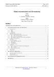
Index
1. Introduction......................................................................................................................................3
2. ReMESH ..........................................................................................................................................4
2.1 Point-and-Click Help .................................................................................................................4
2.2 Navigating the scene ..................................................................................................................5
2.3 Overview of the features ............................................................................................................5
2.4 Example of editing .....................................................................................................................6
2.5 Local Operations ........................................................................................................................7
2.6 Operations on selected regions ..................................................................................................9
2.7 Global operations .......................................................................................................................9
2.8 Checking and Repairing a mesh...............................................................................................10
3. Graphical Settings ..........................................................................................................................12
4. Saving ............................................................................................................................................12
5. Manifold triangle meshes...............................................................................................................13
6. A data structure for manifold triangle meshes ...............................................................................13
6.1 Scheme of the relationships .....................................................................................................14
6.2 A non-redundant data structure................................................................................................15
Bibliography.......................................................................................................................................17
M. Attene
ReMESH
Research and software development involving geometry processing are often slowed down by the
absence of suitable models for testing and benchmark purposes. In particular, when dealing with
triangle meshes, a researcher may need to check the behavior of a new algorithm on several
particular cases. In most situations, the test model is easily conceivable in mind but, at actual
design time, its formalization turns out to be a much harder task than expected. Also, simple
modifications over an existing triangle mesh may become a tedious work without a suitable
interactive environment.
In order to simplify the remeshing of existing models, we have developed ReMESH to
interactively edit manifold triangle meshes, mostly through user friendly actions such as mouse
clicks and drags.
1. Introduction
Due to their simplicity and to the increasing support of hardware producers, triangle meshes are
becoming a de-facto standard in most application areas. A triangle mesh may be produced starting
from another representation, such as a CAD model, or it may approximate a real object which was
captured through modern digitization devices. Digitizing shapes has some interesting analogies with
capturing other sorts of media, such as sound waves and images. As far as sound waves are
concerned, however, there is an important difference that comes from human's perception. In fact,
our ears cannot perceive frequencies above a given threshold, and this guarantees that a uniform,
dense enough discretization of the sound wave is indistinguishable from the original. Differences
would become perceivable if both the original and the discretized waves were pitched down (i.e.
reproduced more slowly), but this rarely makes sense. In contrast, when dealing with 3D objects,
zooming a particular part of the model could be very important, and maintaining an acceptable level
of precision in details can be a difficult task.
In this scenario, surface remeshing is becoming more and more important. Using modern range
scanning devices, in fact, it is possible to acquire real objects with a high level of precision, which
results in a huge number of triangles in the digital model. On the other hand, most applications
cannot afford such a complexity, some may also have strict requirements on the shape of the faces
or on their connectivity, some others may require the sample points to be in particular positions. In
other words, a triangle mesh that is optimal in a particular context may be a bad input for
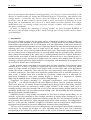
applications belonging to some other contexts (Figure 1). Hence, it is imperative to continue
improving the methods for the remeshing of surface triangulations.
Techniques for global remeshing (i.e. polygonal simplification, mesh optimization for
FEA/FEM, …) are already included in the most diffused software tools for geometric modeling.
These tools, however, are mainly focused on simplifying the design of the overall shape, and thus
rarely provide facilities to interactively modify single elements of the triangle mesh, such as
swapping an edge, removing a triangle, and so on. If a user must necessarily perform such low-level
operations, he/she must rely on a tedious manual editing of the file describing the mesh (assuming
that the file format is human-readable).
ReMESH provides a user-friendly environment for this kind of triangle mesh editing. As an
example, it gives the possibility to split a triangle into three by simply mouse-clicking on it, or to
automatically find and visualize degenerate elements so that the user can interactively modify the
local geometry and connectivity, again, through simple mouse clicks and drags. For completeness,
however, it also provides a number of high-level operations such as triangle mesh simplification,
topological and geometrical correction, subdivision, and many other functionalities.
There are several reasons for low-level editing meshes, the most significant being the production
of test-cases; for example, the designer of a new algorithm may want to test it on a particular
configuration of the connectivity graph of a mesh, or may need to evaluate the numerical robustness
3
ReMESH
M. Attene
under certain circumstances, or may need to establish an invariant behavior of the method under
well-defined transformations of the geometry and/or of the connectivity graph, and so on.
Figure 1: An original object and two triangle meshes approximating it. The two models have about the same number
of faces (~ 5000) but, while the rendering of the leftmost one is more faithful to the original object, the faces of the mesh
on the right are better shaped for further numerical processing. Both the approximating triangle meshes have been
created through ReMESH, starting from a densely sampled version of the model.
2. ReMESH
ReMESH incorporates a wrapper for loading several file formats, including the web standard
VRML 2.0, the older VRML 1.0, the OpenInventor file format (.iv), the Object File Format (.off)
and the SWM, which is the compressed format produced by the SwingWrapper encoder [2]. In all
of the cases, however, the parser assumes that the file has one section describing the vertex
coordinates, and one section describing the triangles (other polygonal faces are not allowed);
further information (transformations, colors, …) is ignored. While loading, a data structure such as
the one described in appendix B is initialized. Some file formats, however, may represent R-sets
which are non-manifold and/or non-orientable. In this case one has two possibilities: 1) Report an
error saying that "the tool cannot manage such a kind of input" or 2) try to perform some
topological corrections in order to find a manifold and orientable approximation of the input that
can be encoded by the data structure. We chose the second strategy, and the loader adds one triangle
at a time to the structure and just skips triangles if they would make the mesh non manifold and/or
non orientable.
Once the loader is settled with the topology and the structure is properly filled, the tool performs
various geometrical checks and corrections (removal of isolated vertices, degenerate triangles, …).
These corrections can be prevented by passing the additional parameter 'nocheck' to the command
line.
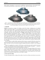
Finally, the graphical user interface (GUI) starts up and shows the model encoded in the data
structure, some information about the model (number of vertices, handles, boundaries, …), and a set
of controls and parameters to be used for the editing (see Figure 2).
If the user wants to operate on more models at the same time, the Append button may be used to
load a triangle mesh from file and to insert it in the current scene without removing the existing
mesh(es). Notice that no geometrical check is performed on the newly loaded mesh that may
consequently have degenerate elements. To automatically remove all the degeneracies of the current
meshes use the buttons provided in the Check & Repair window.
2.1 Point-and-Click Help
To obtain information about a widget of the toolbox, first click on 'Help' and, while the cursor looks
M. Attene
ReMESH
like a hand, click on the desired widget to pop up a help dialog. If no dialog is displayed, it means
that no help is available for that widget.
Figure 2: Screenshot of the graphical user interface of the remeshing tool.
2.2 Navigating the scene
The graphical part of the toolbox is built upon the SGI Open Inventor toolkit, and most of the
facilities for navigating the scene have been inherited from it. For self-containedness, however, we
briefly sketch them here.
The canvas and all of the controls in its window are part of an Examiner viewer component of
Open Inventor. It allows the user to rotate the view around a point of interest using a virtual
trackball. This viewer also allows the user to translate the camera in the viewer plane, as well as
dolly (move forward and backward) to get closer to or further away from the point of interest. The
viewer also supports seek to quickly move the camera to a desired point.
With reference to Figure 2, the three wheels labeled Rotx, Roty and Dolly control respectively the
rotation around the X axis, the one around the Y axis and the dolly. These actions, however, can
also be carried out through direct interaction of the mouse in the canvas.
Further navigation parameters can be controlled through the buttons on the right of the window.
Some aspects of the scene, such as the background color and pictorial properties of the surface
(material, shading, …), can be selected by clicking the button labeled Graphics.
2.3 Overview of the features
At start up, the toolbox shows three windows: one containing the canvas, one showing some
information about the model and one containing some buttons. In the latter there are four buttons
that, when clicked, pop up new windows with additional controls. The Graphics window contains
controls for the appearance of the scene. The Modeling window provides controls for local tasks. In
contrast, the Algorithms window allows the user to perform global tasks on the mesh. The
Check&Repair window contains a number of controls to set tolerances, to check the topological
coherence of the data structure, to remove possible degenerate elements, and so on.
Besides navigation and visualization tasks, the user can perform a number of editing operations,
that we conveniently subdivide into two classes.
Interactive operations: This kind of actions can be performed through mouse-clicks directly on the
surface. Notice that clicks and drags can also be used to navigate the scene. In order to establish the
behavior of mouse events in the canvas without ambiguity, two buttons are provided (the little
5
ReMESH
M. Attene
arrow and the hand on the top-right corner of the window) for switching between visualization and
interactive modes. At start up the mode is set to visualization, the pointer has the shape of a hand
and mouse events are used for navigating the scene. The user can switch to the interactive mode by
clicking on the arrow button and can go back to visualization by clicking on the little hand.
Interactive operations include triangle removal, vertex insertion, edge swapping, shell flipping, and
many others that can be selected from a list of toggle buttons in the Modeling window. Clicking
using the middle mouse button sets the center of a spherical selection that can be used for
processing sub-regions of the mesh.
Other operations: Besides interactive operations, there are several other actions available for the
user in which some parameters are required. In such a case, a new dialog-style window containing
controls on the parameters is shown. For example, if the user wants to simplify the mesh, the
corresponding dialog shows a slider for the selection of the target number of vertices, a toggle
button for choosing whether the boundary has to be simplified or not, and other controls. When
settled with the parameters, the user clicks on the OK button to actually perform the simplification.
Also, non-interactive operations include all of the actions which do not require the specification of a
particular element of the mesh, such as global modifications, or operations which rely on a prior
specification of a selection.
2.4 Example of editing
Before describing the various functionalities, in this section we show a typical example of use of the
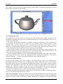
tool. Our objective is to obtain a nice and smooth version of the teapot shown in Figure 2, in which
we want to shorten the spout and remove the cap. The first step of the editing stands at selecting the
part of the spout to be removed. To do this, the user simply middle-clicks on the tip of the spout and
drags a slider. The point of the surface on which the user clicked is the center of a semi-transparent
sphere (see Figure 3) whose radius is interactively controlled through the slider labeled Region
radius in the Modeling window. Also, ReMESH provides a more interactive way to perform
spherical selections, that is, the user middle-clicks on the sphere's center and, without releasing the
middle button, moves the mouse pointer away from the center selected.
Figure 3: Example of spherical selection. The selection includes all of the triangles having their three vertices in the
sphere.
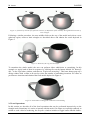
Among the controls provided in the Modeling window, there is a button labeled Remove Region
that, when clicked, eliminates all of the triangles contained in the sphere specified above. After this
operation, the sphere vanishes and the model appears as depicted in Figure 4 a.
Since the user may be unhappy with the zig-zag effect of the new boundary, the toolbox provides
the possibility to manually remove one triangle at a time, simply by clicking on it. So, after the
selection of the toggle button labeled Remove triangles in the Modeling window, the user starts to
click on unwanted triangles until the resulting boundary becomes satisfactory (Figure 4 b).
M. Attene
ReMESH
a
b
Figure 4: (a) Result of removal of a spherical selection. (b) Refinement of the boundary through manual removal of
some triangles.
Following a similar procedure, the user middle-clicks on the top of the model and selects a new
spherical region, removes inner triangles as described above and obtains the result depicted in
Figure 5.
Figure 5: Removal of the cap from the teapot.
To smoothen the whole model, the user can perform either subdivision or smoothing. In this
example we apply both of them in sequence by clicking first on the button labeled "M. Butterfly
Sub." in the Algorithms window, and then on "Laplacian smoothing". This latter button pops up a
dialog window with a slider to be used to select the number of smoothing iterations. We chose to
perform two iterations and obtained the final model depicted in Figure 6.
Figure 6: Final model resulting from subdivision and smoothing.
2.5 Local Operations
In this section we describe all of the local operations that can be performed interactively on the
triangle mesh. Sometimes it is easier to interact with the mesh if its edges are explicitly rendered; to
switch to such a kind of rendering, the Graphics window includes a toggle button labeled hidden7
ReMESH
M. Attene
line. To select a local operation the user must simply click on the corresponding toggle button in the
Modeling window; the viewer is automatically switched to the interactive mode. The operations
provided are:
• Select triangles - When this toggle is set, each triangle the user clicks on is marked as
"selected" and subsequent operations requiring a selection will act only on these triangles. If
the user clicks on a previously selected triangle, it changes its state to "unselected". In order
to display selected triangles using a different color it is possible to switch to par-face color
mode from the Graphics window.
•
Remove triangles - Each triangle the user clicks on is removed from the mesh. The process
takes care of maintaining a coherent data-structure, possibly by duplicating non-manifold
vertices that can be created due to the removal.
•
Swap edges - When the user clicks on (or nearby) an edge, that edge is swapped. Also in this
case, the toolbox takes care of not performing illegal swaps (i.e. boundary edges or resulting
incoherent topology).
•
Insert vertices - When this toggle is set, a new vertex is inserted in the point of the surface
the user clicks on. If such a point is inside a triangle, the insertion is performed through a
triangle-split operation. If it is on (or nearby) an edge, an edge-split operation subdivides
that edge. If it is on (or nearby) a vertex, that vertex is snapped to the position of the point.
In all of the cases, the term "nearby" is quantified by the "Acos tolerance" chosen by the
user in the Check&Repair window. Such a threshold prevents the creation of nearly
degenerate triangles that would be produced by splitting a triangle with a point too close to
one of its edges.
•
Triangulate Holes - When this toggle is set, the user can click on a boundary edge to start a
triangulation routine that tries to fill the corresponding hole. The triangulation approach is
based on a number of heuristics inspired from [16] which try to minimize bad behaviors
such as extreme dihedral angles, degenerate triangles, and so on. No new vertex is inserted.
•
Flip shell - When the user clicks on a triangle, that triangle along with all the other triangles
in the same connected component are reversed, that is, their orientations (and therefore their
normals) are inverted.
•
Remove shell - When this toggle is set, the connected component containing the triangle
clicked is removed from the mesh.
•
Tag Sharp Features - When this toggle is set, the behavior of the clicks is similar to the case
of select triangles, except for the fact that here the user selects edges instead of triangles. To
visualize the selected edges it is necessary to turn on the per-tag mode from the Graphics
window. These edges will receive particular treatment during some other processes.
•
Region radius - To obtain a spherical selection, click on the little arrow (top-right of the
render area) to pass to interactive mode. Then middle-click on the surface to set the center of
the spherical selection and, while keeping the middle button pressed, drag the mouse to
control the radius of the selection. The selection can be remove by middle-clicking again in
the render area. The last radius selected is 'remebered' by ReMesh so, after a first selection,
if the user simply middle clicks another point of the surface, the selection inherits the same
M. Attene
ReMESH
radius as before. This radius, however, can be modified either by keeping the middle button
pressed and dragging, or by releasing the button and using the "Region Radius" slider.
2.6 Operations on selected regions
The toolbox provides the possibility to act on limited regions of the mesh defined through spherical
selections or triangle by triangle. These operations are:
1. Re-triangulate region. This button can be selected from the Modeling window, and causes a retriangulation of the region using a Delaunay-like approach. Specifically, a common plane is
computed as the average of the planes of the triangles selected; then, the vertices of the region
are projected on the plane and an iterative 2D Delaunay optimization is performed, as described
in [5]. Finally, the vertices are moved back to their original positions. This operation is
particularly useful to improve the quality of nearly flat regions.
2. Remove region. As the above one, this button can be selected from the Modeling window, and it
causes the removal of all the triangles belonging to the selected region.
2.7 Global operations
The biggest set of actions provided belongs to the category of global operations. Each one of these
tasks acts on the whole mesh.
3. Normalize. This operation computes the bounding box of the model and normalizes it.
Specifically, it performs a uniform scaling and a translation of the mesh, so that it fits into the
cube [0,1],[0,1],[0,1]. This operation is particularly useful to avoid numerical overflows due to
extreme values of the original coordinates.
4. Transform. This button pops up a dialog containing a number of controls for setting affine
transformations to the whole geometry. While the visualization of the scene being transformed
is interactive, vertex coordinates are actually transformed only when the dialog is closed.
5. Flip Normals. When the user selects this button, all the triangles of the mesh are inverted.
6. Fill Holes. When selected, this button pops up a dialog where the user can select a threshold
number n. Then, all the boundary loops made of at most n edges are patched using the same
strategy as in the local operation Triangulate Holes.
7. Sharp edge tagging. This feature allows the user to automatically tag as sharp (see the local
operation Tag Sharp Edges) all of the edges having an excessive dihedral angle. The threshold
value is selected through a dialog as in the above Fill Holes.
8. Split all edges. This button splits all the edges at their middle points. The geometry of the mesh
does not change but the number of triangles is quadruplicated.
9. Loop subdivide. This button performs a subdivision step using Loop's scheme [14]. Boundary
treatment is provided, while no special rule is implemented to manage sharp edges.
10. M.Butterfly Sub. This button performs a subdivision step using Zorin's modified Butterfly
scheme [17]. Both boundaries and sharp edges are treated properly.
11. Sqrt(3) Subdivide. This button performs a subdivision step based on Kobbelt's approximant
sqrt(3) scheme [12]. No support is provided for boundaries and sharp edges.
12. Laplacian Smooth. This button pops up a dialog where the user can select the number of
Laplacian smoothing iterations to be performed on the mesh. At each iteration, each vertex is
moved towards the center of mass of its neighbors. The amount of movement is controlled by
the parameter "Neighbors' weight" (100% means that in one iteration each vertex is placed
exactly in the center of mass of its neighbors) Tagged sharp edges are smoothened using a onedimensional support.
9
ReMESH
M. Attene
13. Uniform Remesh. This button performs an approximated uniform remeshing of the model. The
number of vertices in the new mesh can be specified in the dialog along with the number of
relaxation steps. Sharp edges and boundaries are handled properly.
14. Open to Disk. This operation performs a topological cut along edges in order to make the mesh
homeomorphic to a disk. Edges and vertices belonging to the cuts are properly duplicated.
15. Spherize. Iterative flattening of highly curved regions. Tips and sharp concavities are greedily
smoothened.
16. Feature Recover. When selecting this button, an Edge-Sharpener filter is run [1]. A dialog is
popped up from which the user may select threshold values (default values are provided). Note
that a zero value of the parameter 'threshold normal angle' implies that the algorithm
automatically computes this value based on an averaging of the angles throughout the whole
surface. Default values are safe for rough meshes obtained through dense and non-adaptive
samplings.
17. Simplify. This button pops up a dialog containing a set of parameters for the simplification. The
user can set the desired number of vertices, choose whether boundaries must be simplified or
not, choose the quality of the simplification (taking into account that as the quality increases the
processing time grows), prevent mesh inversion (also in this case the process becomes slower).
It is important to consider that, due to topological constraints, it cannot be guaranteed that the
target number of vertices is reached. The simplification strategy implemented is a variation of
Garland's method [8].
18. Marching Cubes. This operation remeshes the model using a marching-cubes like pattern. The
user must select the size of the grid, and the process is performed according to the Marching
Intersection paradigm [15]. This functionality is particularly useful to find a single component
approximation of a set of nearly adjacent meshes. Vertices of the new mesh can be forced to
coincide with vertices of the grid. In their turn, vertices of the grid can be forced to be integer
values.
19. Normal noise. This operation distributes Gaussian noise over the vertices in the normal
direction. The amount of noise can be selected by the user in the pop-up dialog as a percentage
of the model's bounding ball radius.
2.8 Checking and Repairing a mesh
The problem of robustness of geometric algorithms has received a lot of attention from more than
15 years [6][7], and it remains a vibrant area of research. When designing a geometric algorithm, in
fact, a researcher uses the theory of real numbers and their exact arithmetic. Such a framework is
often referred to as the Real Arithmetic Model or, more compactly, the RAM. At implementation
time, however, real numbers have to be approximated with finite precision representations and the
error introduced cannot always be neglected. In the context of our remeshing toolbox, such an error
may perturb the geometry and thus cause the creation of degenerate elements, self-intersecting
surfaces, and a number of other flaws. Although a slight error in the geometry may be simply
interpreted as noise, when performing computations such a slight modification may cause a wrong
branching in the process pipeline and, as a consequence, it may cause a topological inconsistence or
a failure of the algorithm.
In order to deal with robustness, we chose to implement a strategy based on the Epsilon
Geometry introduced in [9]. The toolbox provides the possibility for the user to choose a threshold
angle ε. In all of the internal computations, including the loading step, the toolbox prevents the
creation of triangles with angles smaller than ε or bigger than π-ε. Such a prevention is carried out
through swapping and contraction of short edges, inspired from ideas of [3]. The default value of ε
M. Attene
ReMESH
is arcsin(10-5); by experiment, this value proved to be a good compromise between precision and
robustness.
Even if the strategy implemented does not guarantee robustness in all of the cases, we have
found that it avoids nearly all of the most common problems when dealing with remeshing.
Furthermore, it is worth to be considered that if the input model has many degenerate faces
(according to the value of ε) the corrected mesh may be strongly distorted. To cope with this cases,
the toolbox provides a command-line option to set the value of ε to zero, but subsequent processing
must take into account possible failures.
All of the check and repairing tasks can be performed by the user after selecting a new value for
ε. This can be useful when the model being edited is known to become the input for a less robust
system. At run time, the Check&Repair window provides an interactive slider to set the value for ε.
The same window provides a number of buttons for further operations dealing with robustness
issues; in particular the following controls are provided:
1. Check Connectivity. This action performs a sequence of consistency tests on the connectivity
graph of the mesh. Notice that, in normal conditions, it should always pass all of the tests.
However, it has been incorporated to help the developer of a new plug-in to check the status of
the structure at any time.
2. Check Geometry. This action looks for coincident vertices, coincident edges, degenerate
triangles and overlapping adjacent triangles, according to the current value of ε. If one of these
situations is verified, the camera is automatically moved to a viewpoint suitable for showing the
flaw, so that the user can analyze what went wrong, and choose to perform some manual editing
for a possible correction. Also, the user can rely on the automatic correction approaches
provided.
3. Glue Boundaries. This action looks for coincident edges and, if possible, merges them. This is
particularly useful to topologically join several connected components that are usually created
by geometric modeling tools.
4. Remove Smallest Components. This action scans the data structure and removes all of the
connected components but the one with the largest number of triangles. This is useful for
eliminating typical tiny disconnected sheets from models coming from marching-cubes or other
sorts of polygonization algorithms.
5. Orient Normals. This action scans the data structure and, for each connected component orients
the triangle normals consistently. If a connected component is closed, triangle normals are
oriented so that the outer surface is visible (i.e. normals point outwards the enclosed solid).
6. Duplicate non-manifold vertices. This action checks for non-manifold vertices and, for each one
of them, creates a copy of the vertex for each connected component in its original VT. The
incidence relations of the neighboring edges are then updated with the new vertices so as to
have a single component VT for each copy. Notice that this operation is purely topological, that
is, the geometry of the surface is not modified. As for the Check Connectivity button, however,
this should have no effect in normal conditions.
7. Remove Degenerate Triangles. This button performs a removal of possible degenerate triangles.
According to the current value of ε, all of the degenerate triangles are removed from the mesh,
unless their removal would corrupt the topology; in this case, the user must manually remove
these elements (see Check Geometry above). Note that in extreme cases (very large ε or wirelike cylinders connecting two bodies) this action may also cause topological modifications.
8. Remove Overlapping Triangles. This action removes all of the triangles which form an
excessive dihedral angle with one of the neighbors. A dihedral angle is excessive if it is less
than ε of more than π-ε.
11
ReMESH
M. Attene
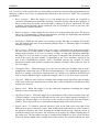
9. Remove Tiny Handles. This action looks for small handles and tunnels, referred to as
topological noise in [10], and removes them from the mesh. The threshold size for handles to be
removed is controlled through the spherical selection tool, which helps the user in having a
visual idea of that size. Resulting holes can be patched through the 'Fill Holes' button.
3. Graphical Settings
ReMesh provides some facilities for interactively setting visualization parameters of the scene being
rendered.
• Material Editor - The material editor is a widget through which the user can control a number
of settings about the material properties of the mesh(es) being displayed. According to
OpenGL's definition of materials, the user may control material reaction to ambient, diffuse,
specular and emissive lightening, as well as surface shininess and transparency. Through the
menu button 'Edit' a material list is provided from which the user may choose a pre-defined
set of material properties. While chaning parameters, the effects are interactively shown in the
main scene, unless 'manual' was chosen from the 'Edit' menu.
• Background Color - This is another set of controls to define the color of the background of
the scene being rendered. These controls are not interactive, that is, the user is required to
select OK to show the result.
• Per-face color - This button toggles the status 'per-face color' which defines wether the mesh
must be rendered with a single material/color throughout the whole surface, or with different
colors for different triangles. When this toggle is set ReMesh shows selected triangles using a
brighter color with respect to the remaining surface. Notice that this feature may slightly
impact on the rendering performances.
• Per-tag color - As ReMesh supports edge tagging, this button allows the user to display edges
currently tagged as 'sharp' using a different color (red). Notice that this feature may slightly
impact on the rendering performances.
• Hidden-line - This button toggles between the default flat-shading and the hidden-line
wireframe shading. More visualization options may be selected through the proper pull-down
menu by right-clicking into the rendering area.
4. Saving
The file format chosen for the output meshes of ReMESH is VRML 1.0 ASCII. There are two
buttons that provide saving facilities:
1. Save as "out.wrl"
The file "out.wrl" is the default filename for work-in-progress models. If ReMesh was launched
from the directory 'MY/PATH', then this button creates the file 'MY/PATH/out.wrl' and saves the
current mesh in it. Notice that if the file already exists ReMesh automatically overwrites it without
asking confirmation, because, again, this file should be considered a "work-in-progress".
2. Save as ...
This button pops-up a file selector from which the user may choose the name of an existing file to
overwrite, or may specify a new file name for the current model. If the file exists confirmation will
be asked before overwriting.
M. Attene
ReMESH
5. Manifold triangle meshes
Let V be a nonempty set. An abstract simplicial complex [11] is a collection Σ of finite nonempty
subsets of V such that every {v} ∈ V belongs to Σ and if A is an element of Σ, then so is every
nonempty subset of A. Each element of V is called a vertex of Σ. An element σ of Σ of cardinality
k+1 is called a k-simplex, and k is the order of σ (hence, a 0-simplex is a vertex). A d-simplex σ is
said to be incident at a k-simplex τ if τ ⊆ σ.
Let Vσ be a set of d+1 affinely independent points in the 3-dimensional Euclidean space R3 , with
d ≤ 3. The subset σ of R3 formed by the points x that can be expressed as the convex combination of
the points v of Vσ:
d
x = ∑ l i vi , with
i =0
d
∑l
i =0
i
= 1, l i ≥ 0
is called an Euclidean d-simplex generated by Vσ, and the points of Vσ are called the vertices of σ.
Any Euclidean s-simplex τ generated by a set Vτ ⊆ Vσ of cardinality s < d is called an s-face of σ.
A finite collection Σ of simplexes is an Euclidean simplicial complex iff the following conditions
hold:
1. For each simplex σ ∈ Σ, all faces of σ belong to Σ;
2. For each pair of simplexes σ and τ, either σ ∩ τ = ∅ or σ ∩ τ is a face of both σ and τ.
Let V be a nonempty set and let Σ be an abstract simplicial complex on V. An embedding of Σ into
R3 is a function f: V → R3, such that:
•
For every k-simplex σ in Σ, the set σ’ generated by the vertices of f(σ) is an Euclidean ksimplex;
•
The collection Σ’ of all the simplexes generated by f, as described above, fulfills condition (2) of
the definition of Euclidean Simplicial Complex.
Thus, an embedding of an abstract simplicial complex is fully defined by mapping its vertices into
points in the Euclidean space. In R3, an abstract simplicial complex Σ endowed with an embedding f
describes a triangle mesh M=(V,E,T) where V, E and T are the sets of 0, 1 and 2-simplexes
respectively and each element of V can be mapped to R3 through f [13].
An element of V is called a vertex, an element of E is called an edge and an element of T is
called a triangle. Furthermore, we call connectivity of M the combinatorial structure of Σ, while we
call geometry of M the function f that associates a 3D point to each vertex of V.
The set |Σ| ⊆ R3 defined as the union of all the Euclidean k-simplexes generated by the vertices
of f(σ), for each σ ∈ Σ, is called the geometric realization of Σ. We say that a triangle mesh is
manifold (possibly with boundary) if |Σ| is a two-dimensional manifold (possibly with boundary).
6. A data structure for manifold triangle meshes
The definition of a data structure for boundary representations, such as triangle meshes, requires the
coding of topological entities (with the associated geometric information) and of a suitable subset of
the topological relationships between such entities. In particular, it is desirable that all of the
following requirements are satisfied:
•
The structure must be complete, that is, it must be possible to extract all of the entities and
relationships which are not explicitly stored, without ambiguity.
•
The structure should be non-redundant, that is, if an entity (or a relationship) can be computed
in optimal time, then it should not be explicitly coded in the data structure.
13
ReMESH
•
M. Attene
Each relationship which is not explicitly stored must be computable in optimal time, that is,
the number of operations required must be linear in the number of elements of the relationship.
6.1 Scheme of the relationships
A topological relation is essentially a function which associates to each element σ of a given type (a
vertex, an edge or a triangle) the set of all the elements of another given type having a topological
connection with σ. For example, if V is the set of vertices of a triangle mesh M = (V,E,T), then the
set of pairs VE = {(v, Υ) | v ∈ V, Υ ⊆ E and ∀ ϕ ∈ Υ, v ⊂ ϕ} is the topological relationship which
relates each vertex with the set of all the edges incident at it. Clearly, the set of pairs VE may be
viewed as a function VE: V →℘(E) which maps each element of V into a subset of E.
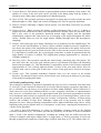
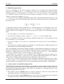
Let M = (V,E,T) be a manifold triangle mesh. The following Figure 7 depicts all of the possible
relationships between elements of M. Notice that a good data structure should not store them all in
order to avoid redundancy.
E
V
T
Figure 7: A scheme of all of the possible relationships between topological entities in a triangle mesh.
Let v be a vertex. VV(v) is the set of all the vertices which are connected to v through an edge1.
VE(v) is the set of all the edges which are incident at v. VT(v) is the set of all the triangles of which
v is a vertex.
Let e be an edge. EV(e) is the set containing the two ending vertices of e. ET(e) is the set of the
triangles of which e is an edge. Notice that, since we consider only manifold triangle meshes
(possibly with boundary), each set ET(e) contains either two elements (when e is an internal edge)
or one element (when e is a border edge). The set EE(e) is the set of the edges bounding the
triangles of which e is an edge, excluding e itself. Thus, if e is an internal edge, the set EE(e)
contains four edges, while if e is on the boundary, |EE(e)| = 2.
Let t be a triangle. The set TV(t) is the set of the three vertices of t. TE(t) is the set of the three
edges bounding t and, finally, TT(t) is the set of the triangles sharing an edge with t.
Moreover, a topological relation may map each element of its domain into a set of constant or
variable cardinality. Hence, when dealing with closed triangle meshes, one can classify the
relationships in:
• Constant relations. These relations map edges and triangles into sets of neighboring elements
with constant cardinality. Specifically, |EV(e)| = 2, |EE(e)| = 4, |ET(e)| = 2, |TV(t)| = 3, |TE(t)| =
3 and |TT(t)| = 3.
•
Variable relations. These relations are vertex-based and the cardinality of the set may vary
depending on which vertex is being mapped (VV, VE and VT).
In the design of a data-structure, however, it is useful to extend the concept of constant relation to
the case of manifold triangle meshes with boundary. In fact, although the cardinality of some
1
The set VV(v) is also known as the link of v.
M. Attene
ReMESH
image-sets is no longer constant, it can assume a finite number of values. Specifically the
cardinality of the EE may be 2 or 4, the one of the ET may be 1 or 2, and the one of the TT may be
0, 1, 2 or 3. All the others are still properly constant.
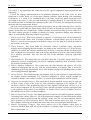
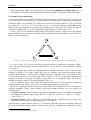
6.2 A non-redundant data structure
Clearly, a data-structure coding all the relations depicted in Figure 7 is redundant. Conversely,
when dealing with manifold triangle meshes with boundary, the scheme depicted in Figure 8 meets
all of the requirements discussed above [4].
E
V
T
Figure 8: Scheme of relations from which it is possible to derive all of the other (non-stored) relations in optimal
time. The dotted line representing the VE indicates that such a relation is only partially stored.
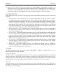
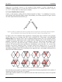
In Figure 8 the VE is indicated with a dotted line, meaning that such a relation is only partially
stored. From now on, we denote with VE* such a restricted VE. VE*(v) maps v into one of its
incident edges. The complete VE(v) can be computed starting from the VE*(v) by "turning around"
v through successive applications of the coded relations, keeping track of the already traversed
triangles. In particular, the initial VE is initialized as the VE*, then choose one triangle of the
ET(VT*(v)), let it be t, and choose the edge e of TE(t) such that v ∈ EV(e) and e ≠ VE*. Now add e
to the set VE and repeat the same operations by considering e as the new VE*. If v is not on the
boundary, the process terminates when e becomes equal to the original VE*(v). If v is on the
boundary, e may become a boundary edge; In this case, the process continues by considering the
unconsidered triangle of ET(VE*(v)) and turns in the opposite sense. An example of this process is
depicted in the following Figure 9.
VE*
VE*
VE*
VE*
v
v
v
v
v
v
v
v
VE*
VE*
VE*
VE*
v
v
v
v
v
v
v
v
Figure 9: Reconstruction of the VE relation starting from the VE*.
Note that this process requires a number of operations that is linearly proportional to the number of
elements of the final VE, therefore it is optimal.
All the other relations which are not explicitly stored in the data structure may be derived in optimal
time as follows:
15
ReMESH
•
VE(v) = construction described above;
•
VV(v) = {w∈EV(e) | e ∈ VE(v) and w ≠ v}
•
VT(v) = {t ∈ ET(e) | e ∈ VE(v)}
•
EE(e) = {f ∈ TE(t) | t ∈ ET(e) and f ≠ e}
•
TV(t) = {v ∈ EV(e) | e ∈ TE(t)}
•
TT(t) = {y ∈ ET(e) | e ∈ TE(t) and y ≠ t}
M. Attene
M. Attene
ReMESH
Bibliography
[1]
[2]
[3]
[4]
[5]
[6]
[7]
[8]
[9]
[10]
[11]
[12]
[13]
[14]
[15]
[16]
[17]
Attene, M., Falcidieno, B., Rossignac, J. and Spagnuolo, M. 2003. Edge-Sharpener:
Recovering sharp features in triangulations of non-adaptively re-meshed surfaces.
Proceedings of the 1st Eurographics Symposium on Geometry Processing, 63-72.
Attene, M., Falcidieno, B., Spagnuolo, M. and Rossignac, J. 2003. SwingWrapper: Retiling
triangle meshes for better EdgeBreaker compression. ACM Transactions on Graphics, 22, 4,
982-996.
Botsch, M. and Kobbelt, L. P. 2001. A Robust Procedure to Eliminate Degenerate Faces
from Triangle Meshes. In Proceedings of Vision, Modeling and Visualization.
Bruzzone, E. and De Floriani, L. 1990. Two Data Structures for Constructing
Tetrahedralizations. The Visual Computer, 6, 5, 266-283.
De Floriani, L., Falcidieno, B. and Pienovi, C. 1985. Delaunay-based Representation of
Surfaces defined over Arbitrarily Shaped Domains. Computer Vision, Graphics and Image
Processing, 32, 127-140.
Forrest, A. R. 1987. Computational geometry and software engineering: Towards a
geometric computing environment. Techniques for Computer Graphics, 23-37.
Fortune, S. 1996. Robustness issues in geometric algorithms. In Proceedings of the 1st
Workshop on Applied Computational Geometry (WACG '96), 9-14.
Garland M. and Heckbert, P.S. 1997. Surface simplification using quadric error metrics. In
Proceedings of ACM SIGGRAPH ‘97, 209-216.
Guibas, L., Salesin, D. and Stolfi. J. 1989. Epsilon geometry: building robust algorithms
from imprecise computations. ACM Symposium on Computational Geometry, 5, 208-217.
Guskov, I. and Wood, Z. 2001. Topological noise removal. In Proceedings of Graphics
Interface ‘01, 19-26.
Hatcher, A. 2002. Algebraic Topology. Cambridge University Press, UK.
Kobbelt, L. 2000. Sqrt(3)-subdivision. In Proceedings of ACM SIGGRAPH '00, 103-112.
Lee, A. W. F., Sweldens, W., Schröder, P., Cowsar, L. and Dobkin, D. 1998. MAPS:
Multiresolution adaptive parameterization of surfaces. In Proceedings of ACM SIGGRAPH
‘98, 95-104.
Loop, C. 1987. Smooth subdivision surfaces based on triangles. Master’s thesis, University
of Utah (USA), Department of Mathematics.
Rocchini, C., Cignoni, P., Ganovelli, F., Montani, C., Pingi, P. and Scopigno, R. 2001.
Marching Intersections: an efficient resampling algorithm for surface management. In
Proceedings of Shape Modeling International (SMI ’01), 296-305.
Schroeder, W., Zarge, J. and Lorensen, W.E. 1992. Decimation of triangle meshes. In
Proceedings of ACM SIGGRAPH ‘92, 65-70.
Zorin, D., Schröder, P. and Sweldens, W. 1996. Interpolating subdivision for meshes with
arbitrary topology. In Proceedings of ACM SIGGRAPH '96, 189-192.
17