1
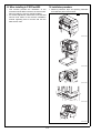
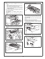
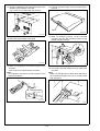
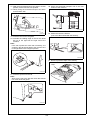
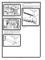
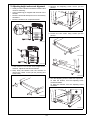
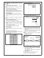
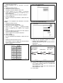
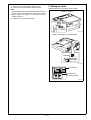
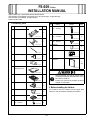
FS-609 Finisher
INSTALLATION MANUAL
Applied Machines: C353/C253/C203/C353P/mc8650
COLOR MFP (Color/B&W): 35 ppm/35 ppm, 25 ppm/25 ppm, 20 ppm/20 ppm
COLOR PRT (Color/B&W): 35 ppm/35 ppm
Product Code: A02E
I. Accessory parts
No.
Name
No.
Shape
Q’ty
Name
Shape
Q’ty
12. Screw B
(4 × 30 mm)
1. Rail guide
1
1
4583IXC004DA
13. Screw C
(4 × 12 mm)
A0D6IXC001DA
2. Ground plate
4
4583IXC005DA
14. Screw D
(4 × 8 mm)
1
2
A0D6IXC032DA
A0D6IXC002DA
15. Spacer
3. Rail
1
1
A0D6IXC008DA
16. Label
A0D6IXC003DA
1
4. Positioning pin
1
4698U107AA
17. Installation
Manual
A0D6IXC029DA
5. Magnet plate
1
set
1
A0D6IXC004DA
6. Horizontal
transport unit
4980IXC019DA
1
A0D6IXC005DA
7. Exit tray
After unpacking, be sure to get rid of the
packaging materials and keep them out of
the reach of children.
1
Putting your head in the wrapper involves
danger of suffocation.
A0D6IXC006DA
8. Staple cartridge
1
II. Before Installing the finisher
A0D6IXC007DA
9. Cord clamp
The machine must be outfitted with the paper feed
cabinet or the desk before installing the finisher.
1
A0D6IXC030DA
10. Ferrite core
1
A0D6IXC031DA
11. Screw A
(4 × 6 mm)
4
4583IXC003DA
E-1
A0D6-9560-00
III. When installing to C353P/mc8650
IV. Installation procedure
• This manual provides the illustration of the
machine used as MFP. However, the same installation procedure is used for C353P/mc8650.
• For screen adjustment, make sure to use the field
service tools. Refer to the machine installation
manual regarding how to connect and use the
field service tools.
1. Remove protective tape and packing materials
from different parts of the finisher.
Tape
A0D6IXC047DA
A0D6IXC048DA
A0D6IXC049DA
A0D6IXC050DA
A0D6IXC051DA
E-2
Note:
• Make sure that the installation site is flat and
level.
• After the Finisher has been set up, avoid moving it unless it is absolutely necessary.
See “VIII. Removing the Rail” of P.E-8 to move
it. After moving it, follow step 15 to 20 of P.E-4
and step 23 of P.E-5.
2. Turn off the machine and unplug the power cord
from the power outlet.
* For installation to mc8650, perform steps 3
through 8.
3. Open the right door, and open the paper exit
cover.
6. Remove the actuator (two screws).
A0DAIXC029DA
7. Open the paper exit section and attach the paper
exit cover that was removed in step 4 (two claws
and one screw).
8. Close the paper exit cover, and close the right
door.
9. Remove the sub tray of the machine.
* Remove it while pushing the claws of the sub tray
in the direction of the allow ➀ shown on the illustration and unhook.
A0DAIXC026DA
4. Remove the paper exit cover (two claws and one
screw).
➀
➀
A083IXC006DB
10. Peel off the seal covering the area where the
stabilizing pin and magnet plate will be attached.
A0DAIXC027DA
5. Close the paper exit section.
A0D6IXC033DA
A0DAIXC028DA
E-3
14. Remove protective tape of the horizontal transport unit.
11. Attach the stabilizing pin and magnet plate to the
left side of the machine as shown
(four screw C’s furnished with the finisher).
Tape
A0D6IXC036DB
A0D6IXC034DB
15. Mate the attaching portion of the horizontal
transport unit with the mounting bracket at the
finisher entrance section.
12. Place the ground plate in rail guide.
A0D6IXC009DA
A0D6IXC010DA
13.Attach the rail guide to the bottom left part of the
machine
(two screw D’s furnished with the finisher).
Note:
Fit rail guide in the tab on the lower portion of the
paper feed cabinet.
16. Press the horizontal transport unit up against the
rear side.
Note:
Make sure that the gear on the finisher and that on
the horizontal transport unit are in positive mesh
with each other.
A0D6IXC035DC
A0D6IXC011DA
E-4
17. With the horizontal transport unit kept in a level
position, fit the lock lever into position.
18. Gently swing the horizontal transport unit down
to the finisher side.
22. Place the horizontal transport unit on the exit
section of the machine.
A0D6IXC038DA
23. Attach the rail to the finisher
(one screw B furnished with the finisher).
A0D6IXC012DA
19. Insert the rail into the rail guide.
20. Protrude the leading edge of the rail out about
60 mm to the right from the right end of the
machine.
Note:
If the rail is pulled out more than necessary, it is
caught by the flat spring fitted to the machine as it
is brought back into the original position.
A0D6IXC013DA
24. Remove protective tape of the exit tray.
Tape
A0D6IXC037DB
21. Insert the spacer into the rail.
Note:
Slide out the rail to the left and check that it does
not come off the rail guide.
A0D6IXC014DA
A0D6IXC046DA
E-5
28. Install the ferrite core furnished with the finisher
as shown in the illustration.
Note:
When installing the ferrite core, be careful so that
the cable is not pinched between the upper and
lower pieces of the ferrite core.
25. Hook the mounting hooks of the exit tray onto
the catches provided on the finisher exit section.
A0D6IXC015DA
26. Secure the exit tray into position
(four screw A’s furnished with the finisher).
A0D6IXC040DB
29. Attach the lower right cover that was removed in
step 27.
A0D6IXC016DA
*
Steps 27 through 29 need to be performed when
the machine is equipped with the 1 way paper
feed cabinet or the 2 way paper feed cabinet.
27. Remove the lower right cover from the paper
feed cabinet (two screws).
A0D6IXC039DA
E-6
V. Adjusting height and correct alignment
3. Remove the adjusting screw covers (at four
places).
1. Gently move the finisher toward the machine and
check for following.
• Is the positioning pin aligned with the hole in the
finisher?
• Does the horizontal transport unit run excessively
slantwise?
• Does the clearance at A equal that at B?
A0D6IXC018DA
4. Loosen the two caster fixing screws (at four
places).
A0D6IXC041DA
A
B
A0D6IXC019DA
A0D6IXC042DA
* If the finisher is not at the same height as the
machine, adjust the machine as follows.
2. Keep away the finisher from the machine to
remove the caster covers (at two places) (one
screw each).
A0D6IXC020DA
5. Turn the adjusting screw to make the adjustment.
To raise the finisher, turn the adjusting screw
counterclockwise.
To lower the finisher, turn the adjusting screw
clockwise.
A0D6IXC017DA
A0D6IXC021DA
E-7
VII. Connecting the hookup cord
6. Tighten the caster fixing screws which has been
loosened in step 4.
7. Reinstall the adjusting screw covers which has
been removed in step 3.
8. Reinstall the caster covers which has been
removed in step 2 (one screw each).
1. Connect the hookup cord to the horizontal transport unit and the machine.
VI. Installing the staple cartridge
1. Open the front door of the finisher and slide out
the staple unit.
2. Remove the staple cartridge from its protective
bag.
3. Insert the staple cartridge into position until a click
is heard.
A0D6IXC043DA
2. Attach the cord clamp to secure the hookup cord
that comes from the horizontal transport unit.
Note:
There should be no slack in the cord between the
lattice connector and the cord clamp.
A0D6IXC022DA
4. Close the front door.
A0D6IXC044DA
VIII. Removing the rail
1. Remove the screw on rail at the finisher side (one
screw).
2. Disconnect the two hookup cords.
3. Remove the horizontal transport unit from the finisher, and then place it on top of the machine.
4. Carefully pull the finisher away from the machine.
5. Slide the rail under the machine, and then
remove it from the right side of the machine.
E-8
IX. Adjusting the staple position and fold
position
9. Touch “FN-X3Adjustment.”
<Adjusting center-staple position>
-Machine equipped with an automatic document
feeder1. Load the drawer with A3
or Ledger
paper.
2. Select the functions as follows:
Finishing→Center Staple & Fold→Yes.
3. Load a 5-page A3
or Ledger
document
(blank sheets of paper may be used) in the document feeding tray.
* Use a 5-page document to minimize variations.
4. Press the Start key.
* For the subsequent procedures, follow from the
step 7.
A0D6IXE026DA
10. Touch “Center-Staple Position Adj.”
-Machine not equipped with automatic document
feeder1. Load the drawer with A3
or Ledger
paper.
2. Select the functions as follows:
Finishing→Center Staple & Fold→Yes.
3. Place an A3
or Ledger
original (a blank
sheet of paper may be used) on the original
glass.
4. Press the Start key five times (to let the machine
scan the original five times).
* Use a 5-page set to minimize variations.
5. Touch “Finish.”
6. Press the Start key.
* For the subsequent procedures, follow from the
step 7.
A0D6IXE027DA
11. Fold the copy set fed out of the machine in half.
* Call the copy page facing up A and the that facing down B.
12. Check for any deviation between the stapled
position and the newly folded crease.
Note:
Use the newly folded crease, not the machinefolded one, for the check.
Standard: 0 ± 2 mm
7. Display the Service Mode screen.
(For details of how to display the Service Mode
screen, see the Service Manual.)
8. Touch “Finisher.”
<Decrease the
value toward
the - end.>
<Reference>
<Increase the
value toward
the + end.>
A
A
A
B
B
B
A00JIXE118DA
4698U068AA
4698U069AA
4698U070AA
13. Use the
or
key to make the adjustment.
If the staple is on the side of A, decrease the
value toward the - end.
If the staple is on the side of B, increase the
value toward the + end.
14. Touch “END.”
15. Touch “Exit” on the Service Mode screen.
16. Make the copy and check again.
E-9
<Adjusting fold-position>
-Machine equipped with an automatic document
feeder1. Display the basic screen.
2. Select the functions as follows:
Finishing→Center Staple & Fold→Yes.
3. Load a 5-page A3
or Ledger
document
(blank sheets of paper may be used) in the document feeding tray.
* Use a 5-page document to minimize variations.
4. Press the Start key.
* For the subsequent procedures, follow from the
step 7.
9. Touch “FN-X3Adjustment.”
A0D6IXE026DA
-Machine not equipped with automatic document
feeder1. Display the basic screen.
2. Select the functions as follows:
Finishing→Center Staple & Fold→Yes.
3. Place an A3
or Ledger
original (a blank
sheet of paper may be used) on the original
glass.
4. Press the Start key five times (to let the machine
scan the original five times).
* Use a 5-page set to minimize variations.
5. Touch “Finish.”
6. Press the Start key.
* For the subsequent procedures, follow from the
step 7.
7. Display the Service Mode screen.
(For details of how to display the Service Mode
screen, see the Service Manual.)
8. Touch “Finisher.”
10. Touch “Half-Fold Position Adj.”
A0D6IXE028DA
11. Check for any deviation between the stapled
position and the folded crease.
* Call the copy page facing up A and the that facing down B.
Standard: 0 ± 2 mm
<Increase the
value toward
the + end.>
<Reference>
<Decrease the
value toward
the - end.>
A
A
A
B
B
B
A00JIXE118DA
4698U112AA
4698U069AA
4698U113AA
12. Use the
or
key to make the adjustment.
If the staple is on the side of A, increase the
value toward the + end.
If the staple is on the side of B, decrease the
value toward the - end.
13. Touch “END.”
E-10
14. Touch “Exit” on the Service Mode screen.
15. Turn OFF and ON the Main Power Switch.
Note:
When displayed the Service Mode screen, be sure
to turn off the main power after exiting the Service
Mode screen and wait for 10 seconds or more
before turning on.
X. Affixing the Labels
Affix the labels to the position shown below.
Label for machine
16. Make the copy and check again.
A01GIXC038DA
Label for automatic document feeder
A0D6IXC045DA
for machine
for automatic
document feeder
4698U107AA
E-11