1
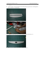
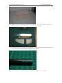
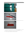
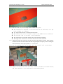
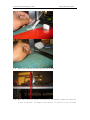
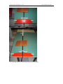
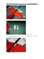
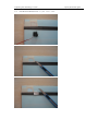
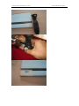
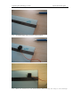
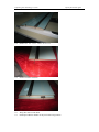
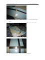
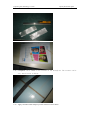
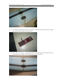
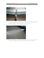
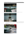
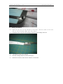
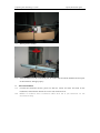
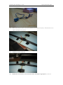
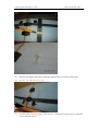
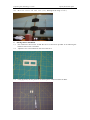
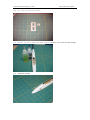
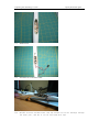
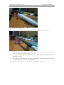
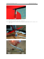
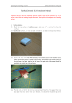
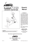
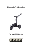
Topsoaring New Technology Co.,LTD.
Top Sky DLG install guide
TopSky DLG Installation Manual
Attention: Because after the compound materials solidify, there will be ammonia iris on the
surface, which affect the bonding strength afterwards. Please polish with sandpaper on all bonding
surface.
1. Tail Installation
1.1. Sand the top surface of stabilizer mount, make sure it’s vertical to the side
surface.
1.2. Sand the side surface, or you can make streamline as shown in the picture below.
1.3.
Cover the tail boom with 300# sandpaper, then sand the groove of the stabilizer mount.
Make sure that the groove is parallel to the fuselage, and parallel to the outside surface of
the tail boom. And after bond to the tail boom, the upper side of the mount should be
parallel to the central line of the tail boom.
1.4.
Polish, cut, or drill the tail as your personal favorite. We suggest that you
may make the rear end of the tail thinner. It should be weighted 12g after
Topsoaring New Technology Co.,LTD.
Top Sky DLG install guide
1.5.
sanding.
Cut the elevator. You may decide the size and shape based on your favorite. Cut through the 2
holes on the balsa is recommended.
1.6.
Sand the gap for the hinge.
1.7.
1.8.
Bond the carbon cloth into the tail. The weight of the tail should be13g then.
Wait for the solidity with heavy weight pressing.
Topsoaring New Technology Co.,LTD.
1.9.
Top Sky DLG install guide
Make a slot on the front end of the vertical tail. The width is the same as
the diameter of the tail boom, and the length is 10mm.
1.10. Slotting the tail boom: width 2.5mm, length 20mm. Make sure the edge of the two slots are
smooth. You may sand it with 300#sand paper after cutting.
1.11. Joint the tail boom and the vertical tail. Sand if not fitting.
Topsoaring New Technology Co.,LTD.
Top Sky DLG install guide
1.12. First cover the tail side with hinge.
1.13. Then, cover the other side. The weight of tail set with films should be 14g then.
1.14. Cut the covering of both side of the vertical tail: 2mm inside the edge of
the carbon, cut from the front to the end of the tail boom.
1.15. Bond the tail boom and the vertical tail, with fiberglass and epoxy.
1.16. Cut the covering of the stabilizer, 2mm inside of the carbon.
Topsoaring New Technology Co.,LTD.
Top Sky DLG install guide
1.17. Fix the tail on your working board. Check the joint:
z The stabilizer is parallel to the center line of the tail boom, or it may
have an angle of -1 degree.
z The hinge of the elevator is vertical to the tail boom.
z The center line of the tail boom is right in the middle of the stabilizer.
z The vertical tail is vertical to the stabilizer.
z The vertical tail is on the same surface as the center line of the fuselage.
z The hinge of the vertical tail is vertical to the center line of the tail boom.
1.18. Temporarily joint the vertical tail and the tail boom with Adhesive Sticker. Then bond the
tail boom and the vertical tail from both side using fiberglass and epoxy. There is fiberglass
in the accessories. And e-proxy 30min is recommended .
1.19. Lie the fuselage flat on the desk, with the vertical tail up side down.
1.20. Adjust the center line of the tail boom, to make it parallel to the desk surface,
and also parallel to the scale mark on the working board.
Topsoaring New Technology Co.,LTD.
Top Sky DLG install guide
1.21. With a ruler, make the vertical tail be vertical to the desk.
1.22. With the scale mark, adjust the stabilizer and the mount. When the stabilizer
is flat on the desk, the hinge of the elevator is vertical to the tail boom.
Topsoaring New Technology Co.,LTD.
1.23. Bond the stabilizer mount and the tail boom with fast glue.
Top Sky DLG install guide
Topsoaring New Technology Co.,LTD.
Top Sky DLG install guide
1.24. Cut appropriate size of fiberglass with a paper template.
1.25. Apply a thin layer of epoxy on the boom, stabilizer carbon and the mount.
1.26. Joint the tail boom and the mount to the bottom of the stabilizer with epoxy and fiberglass.
Waiting for the solidify.
2.
Wing installation
Topsoaring New Technology Co.,LTD.
2.1.
Cut the servo mount based on your servo size.
Top Sky DLG install guide
Topsoaring New Technology Co.,LTD.
Top Sky DLG install guide
Topsoaring New Technology Co.,LTD.
Top Sky DLG install guide
2.2.
Check the shape with your servo. Trim if not fit.
2.3.
Mark the location of the screw holes, when putting the wing on the fuselage.
Topsoaring New Technology Co.,LTD.
2.4.
Drill holes for servo cable with file.
2.5.
Drill screw holes with file.
2.6.
2.7.
Wing face down on the desk.
Put Paper Adhesive Sticker on the joint of the wing bottom.
Top Sky DLG install guide
Topsoaring New Technology Co.,LTD.
2.8.
2.9.
Top Sky DLG install guide
Prepare the platform for solidify of the wing joint. The wing dihedral angle 6.3
degrees.
Put the wing on the platform, then joint with 6min epoxy or fast glue..
2.10. Record the locations of screw holes and servo cable holes.
2.11. Apply fiberglass and epoxy on the joint area, the width is about 6mm.
Topsoaring New Technology Co.,LTD.
Top Sky DLG install guide
2.12. Cellophane can be added on the outside of the fiberglass. The surface can be
very smooth after solidify.
2.13. Apply 1k carbon cloth and epoxy on the location of screw holes.
Topsoaring New Technology Co.,LTD.
Top Sky DLG install guide
2.14. Cut the 6mm carbon pipe into 3 pieces as 60mm,12mm and 7mm in length. They are finger
peg, front screw sleeve and rear screw sleeve.
2.15. Drill 4mm screw holes. Trim the wing screw holes and make them homocentric to the
screw holes on the fuselage. Then enlarge the holes with 6mm drill.
Topsoaring New Technology Co.,LTD.
Top Sky DLG install guide
2.16. Insert 2 short carbon pipes into the wing screw holes, and assemble the wing onto the
fuselage.
2.17. Put on the tail boom, and make sure the wing is vertical to the center line
of the fuselage. Check the length between the wing tips to the vertical tail.
Both side should be the same. Trim the screw holes if not.
2.18. Cover the screw holes on the fuselage with tape.
2.19. Bond the screw tube on to the wing. And assemble the wing on the fuselage with
two screws. Slightly loosen the screws when the epoxy half solidify.
Topsoaring New Technology Co.,LTD.
Top Sky DLG install guide
2.20. After the wing’s solidify, sand the screw tube to make them flush with the wing.
2.21. Locate the finger peg position as your favorite. We suggest it’s on the center line of the
carbon wing beam, and 10mm to the outside edge of the wing tip. Drill 6mm holes on the
holder location.
2.22. Bond the peg onto the wing with epoxy.
Topsoaring New Technology Co.,LTD.
Top Sky DLG install guide
3. Fuselage Installation
3.1. Sand the rear part of the fuselage if necessary, and the inside of the front
part of the tail boom. Make sure they match.
3.2. Drill hole on the rear part of the fuselage, preparing for the linkage of the tail.
3.3.
3.4.
3.5.
Assemble the wing on the fuselage.
Bond the fuselage and the tail boom with epoxy.
Rotate the tail boom, make sure the stabilizer is horizontal.
Topsoaring New Technology Co.,LTD.
Top Sky DLG install guide
3.6.
Waiting for the solidify.
3.7.
If the tail boom was cut on the front part, 3k carbon fiber should be added to the front part
of the tail boom, and apply epoxy.
4. Aileron Installation
4.1. Connect the electronic devices, power on and test. Center all sticks and trims on the
transmitter, and center the aileron servo arm. Turn of the receiver.
4.2. Solder an aileron servo extension cable with the 4 pin connector in the
accessories bag.
Topsoaring New Technology Co.,LTD.
Top Sky DLG install guide
4.3.
Glue the aileron servo into the installation hole with epoxy. Extend the servo
cable through the groove.
4.4.
Solder the aileron connector.
4.5.
Make holes on the aileron, insert the aileron horn, and adjust to appropriate position.
Topsoaring New Technology Co.,LTD.
Top Sky DLG install guide
4.6.
4.7.
Measure the length of the link rod. Bend the supplied steel wire into the same length.
Install the aileron link rod.
4.8.
Test the aileron servo by power on the receiver.
arm to center the aileron.
Then power off the receiver. Adjust the
Topsoaring New Technology Co.,LTD.
4.9.
Top Sky DLG install guide
Bond the servos and arms with epoxy. Waiting for the wing solidity.
5. Fuselage device installation
5.1. Put in batteries and receiver. Install the servo as forward as possible if not affecting the
batteries and receiver’s assemble.
5.2. Adjust the servo mount based on the size of the servo.
5.3.
Using plywood, cut two pieces of 7x15mm squares. Drill 1mm holes on them.
Topsoaring New Technology Co.,LTD.
Top Sky DLG install guide
5.4.
Cut slots on the servo mount.
5.5.
Install the servo mount and wood squares. Bond the servo mount onto the fuselage.
5.6.
Install the rod tube.
Topsoaring New Technology Co.,LTD.
Top Sky DLG install guide
5.7.
Install servos.
5.8.
Install the servo extension cable.
5.9.
Install receiver and batteries. Run the antenna out of the fuselage through
the front part, and fix it on the tail boom with tape.
Topsoaring New Technology Co.,LTD.
Top Sky DLG install guide
6. Install devices on the tail.
6.1. Run the tube from the fuselage to the tail through the tail boom. Fix it with tape.
6.2.
6.3.
6.4.
6.5.
Insert 0.5mm steel wire into the tube. Make sure the wire can move smoothly.
Sand the wire with 300# sandpaper if not.
Cut slots on rudder and elevator, put in the horn without glue, then adjust them into
appropriate position.
Cut a piece of balsa wood. Put it at the end of the rudder rod tube. Trim the shape of the
wood, and make sure the rod doesn’t get pressure.
Fix the tube onto the tail boom with fiberglass and epoxy.
Topsoaring New Technology Co.,LTD.
6.6.
6.7.
6.8.
7.
Top Sky DLG install guide
Make a Z bend on the wire with pliers.
Reinstall the horns with wires connected.
Power on the receiver, center the servo, then glue the horns on the control surface with
fast glue.
Finish
Topsoaring New Technology Co.,LTD.
Top Sky DLG install guide
8. Checking
8.1. Check the center of gravity: Install batteries, receiver and fuselage cover.
Make sure the CG is 75-80mm behind the leading edge at the middle of the wing.
Changing weight on the nose or tail to adjust the CG. The best CG position
should be decided during flight.
8.2. Control surface testing: Make sure all devices are installed firmly and the position is
accurate.
.