1
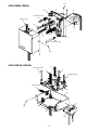
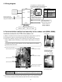
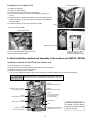
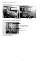
INSTALLATION MANUAL
Digital Inverter Air Conditioner
Application Control Kit
Use for Outdoor Unit Only
Model:TCB-PCOS1E2
For Installation Professionals
•
Please read this manual thoroughly before starting the installation work, and install the
products correctly.
CAUTIONS for SAFETY
WARNING
Ask an authorized dealer or qualified installation professional to install/maintain the air conditioner.
• Inappropriate installation may result in electric shock or fire.
Perform installation work surely based on this Installation Manual.
• Incomplete installation causes an electric shock or a fire.
Ask an authorized dealer or qualified installation professional to reinstall adapters.
• Incomplete installation causes an electric shock or a fire.
For an electric work, this Installation Manual shall be referred and exclusive circuit shall be
necessarily used. The used voltage shall be also match with the rated voltage of the product.
• If there is capacity shortage of electric circuit or installation work is poor, an electric shock or a fire may be caused.
CAUTION
• Using the specified wires, surely connect wires so that external force of wire is not applied to
connecting part of the terminals; otherwise disconnection, heating or fire will generate.
• For wiring work, use wires with correct current capacity; otherwise earth leakage, heating or fire will generate.
• Do not apply an excessive force on the board body, otherwise bending, separation, or disconnection
generates resulted heating or fire.
• After installation work, execute a test run to confirm there is no trouble.
And also ask the customers to keep this Manual by themselves.
1. Object model
RAV-SM56*AT-E, SM80*AT-E
RAV-SM110*AT-E, SM140*AT-E
1
2. Accessories
Name
Wire(A) (Yellow connector : 5-core)
Wire(B) (Blue connector : 2-core)
PCB
Wire(C) (Red connector : 2-core)
Wire(D) (Blue connector : 5-core)
Transformer
Fixing plate(A)
Cover
Fixing plate(B)
Spacer
Clamp
Screws(A) (M3 x 6 )
Screws(B) (M4 x 8 )
Binding band
Holder
Installation Manual
Q'ty
1
1
1
1
1
1
1
1
1
4
2
2
4
3
2
1
• Power peak-cut control
Use
• Night operation
(Sound reduction)
• Compressor operation output
Application
Connecting wire for Night operation(Sound reduction) control or Power peak-cut control
Connecting wire for Compressor operation output
Application control PCB
Connecting wire for Power supply
Connecting wire for Communication line
Fixing plate(SM56,80)
For fixing plate(A)
Fixing plate(SM110,140)
For fixing Application Control PCB
For fixing plate(B)
For fixing Transformer
Fixing screws for mounting fixing plate and cover
Used to process wires for binding the wires
This Manual
Correspond to the temporary power peak-cut control by controlling the capacity of the
outdoor unit using an external signal.
Capacity control is made in 3 steps of 75%, 50% and Operation stop.
The capacity is controlled using a timer procured on site (to be purchased locally)
regardless of the outdoor temperature and load to reduce the sound level of the operation.
Outputs a dry contact ON signal when the compressor is in operation.
3. How to install
No.
Name
Q'ty
1
2
3
Wire(A)
Wire(B)
PCB
1
1
1
4
Wire(C)
1
5
Wire(D)
1
6
7
8
9
10
11
12
13
14
15
16
Transformer
Fixing plate(A)
Cover
Fixing plate(B)
1
1
1
1
4
2
2
4
3
2
1
Spacer
Clamp
Screws(A)
Screws(B)
Binding band
Holder
Installation manual
Q'ty to be used
Work items
RAV-SM56,80 RAV-SM110,140
Connect a timer (local procurement) to the CN300 of PCB
1
1
Connect a timer (local procurement) to the CN201 of PCB
1
1
1
1
Connect between the CN100 of the PCB and faston receptacle of terminal
1
1
block for power supply of the outdoor unit.
Connect between the CN400 of the PCB and the PCB of the outdoor unit.
1
1
(SM56,SM80 : CN806 SM110,SM140 : CN804)
Connect to the CN101 and CN102 of PCB
1
1
1
1
1
For attaching PCB
4
4
For fixing Wire clamp
2
For fixing Transformer
2
2
For fixing plate(A), Cover, and fixing plate(B)
2
4
Used suitably
3
3
2
1
1
2
13 2
<RAV-SM56, SM80>
3
10 4
6
(Transformer wire)
6
(Wire(D) only)
5
4
2
12 2
1
5
7
6
(Transformer wire)
13 2
8
<RAV-SM110, SM140>
5
(Transformer wire)
1
6
2
(Transformer wire)
6
(Wire(D) only)
5
4
3
9
6
13 2
10
11 2
12 2
3
4. Wiring diagram
Transformer
Wire(C)
Faston receptacle of
terminal block for power
supply of the outdoor unit
An Outdoor unit is controlled as follows
by connecting between a white and each line
using Timer or Switch purchased locally.
Local Supply
PCB
White
White Common
Night operation
Black
CN101
Black (Sound reduction by
5dB at cooling mode)
Yellow
CN300
Power
peak-cut 0%
Orange
Yellow operation
CN102
(stop)
Red
peak-cut
Orange Power
50% operation
Caution
peak-cut
Red Power
75% operation
Don't connect two or more
contacts of power peak-cut with
CN201
CN100
white line at the same time.
Compressor operation output
Non-voltage ON/OFF
output signal (Dry contact)
(
CN400
(to be purchased locally)
Wire(D)
)
DC250V, 10mA to 1A
DC24V, 10mA to 1A
DC12V, 10mA to 1A
Inverter assembly PCB of the outdoor unit
• SM56,80 : CN806
• SM110,140 : CN804
5. Parts installation method and assembly to the outdoor unit (SM56, SM80)
Installation method for the PCB of the outdoor unit
Fixing plate(A)
(1) Mount a Transformer to the rear side of the Fixing plate(A) using Screws(A) (2 pieces).
(2) Install Spacers (4 pieces) and PCB to the front side of the Fixing plate(A).
(3) Connect the Lead wires (2 types) of the Transformer to the CN101 and CN102 of the
PCB. In addition, connect the Wire(C) (2-core) to CN100 and the Wire(D) (5-core) to
CN400.
To connect the Wire(A) and the Wire(B), refer to the Wiring diagram of installation
method to connect the wires.
Transformer
Lead wires of the Transformer
(connected to the CN101)
Wire(C)
(connected to the CN100)
Screws(A)
(2 pieces)
Extract the wires other
than the wire(D) from
this cut-away section
Wire(A)
(connected to the CN300)
Cover
Screws(B)
(2 pieces)
Wire(B)
(connected to the CN201)
Wire(D)
(connected to the CN400)
Lead wires of the Transformer
(connected to the CN102)
PCB
CAUTION
Spacer
(4 pieces)
Extract the wire(D) from
this cut-away section
Don't allow the wires to come into pinching with cover parts.
Otherwise, the wires may be broken or heated or fire may occur.
(4) Close the cover to the Fixing plate(A) with Screws(B) (2 pieces). Pass the wires through
the cut-away section of the cover and do not allow the wires to come into pinching.
4
Assembly to the Outdoor Unit
Screws(B) (2 pieces)
(1) Remove the Top plate.
(2) Remove the Front cabinet.
(3) Remove the Cover of packed valve and wiring lid.
(4) Fix the PCB assembly to the Inverter assembly with Screws(B) (2
pieces).
(5) Remove the power supply terminal block cover of the outdoor unit and
connect the Wire(C) (2-core) to the faston receptacle of terminal block
for power supply.
(6) Connect the Wire(D) (5-core) to the Inverter assembly.
Cover
• Connect the wire to CN806.
connect to the CN806
Application Control Kit
Connect the Wire(C) (2-core) to
the faston receptacle of the
terminal block for power supply.
(7) Tie the wire with binding band, if necessary.
(8) Re-assemble the Front cabinet.
6. Parts installation method and assembly to the outdoor unit (SM110, SM140)
Installation method for the PCB of the outdoor unit
(1) Fix the clamp to the Fixing plate(B).
(2) Fix the Spacers(4 pieces) and PCB to the front side of the Fixing plate(B).
(3) Mount the Transformer to the Fixing plate(B).
(4) Connect the Wire(D) (5-core) to CN400.
Pass the wires through the Clamp section of the Fixing plate(B) and do not allow the wires to come into pinching.
CAUTION
Don't allow the wires to come into pinching with cover parts.
Otherwise, the wires may be broken or heated or fire may occur.
Wire(C)
(connected to the CN100)
Wire(A)
(connected to the CN300)
Lead wires of the Transformer
(connected to the CN101)
Clamp
(Extract the wires other
than the wire(D) from
this clamp section)
Wire(B)
(connected to the CN201)
Wire(D)
(connected to the CN400)
Fixing plate(B)
PCB
Clamp
(Extract the wire(D)
from this clamp section)
Lead wires of the Transformer
(connected to the CN102)
Spacer (4 pieces)
5
To connect the Wire(A) and
the Wire(B), refer to the Wiring
diagram of installation method
to connect the wires.
Assembly to the Outdoor Unit
(1) Remove the Front cabinet.
(2) Fix the Application Control Kit to the Inverter assembly with Screws(B) (2 pieces).
Install the Application
Control Kit in the back
of Inverter assembly.
Application Control Kit
Screws(B) (2 pieces)
(3) Connect the Wire (D) (5-core) to CN804 of the SUB PCB.
SUB PCB
Connect the Wire(C) (2-core) to
the faston receptacle of the
terminal block for power supply.
Holder (2 pieces)
connect to the CN804
(4) Tie the wire with binding band, if necessary.
(5) Re-assemble the Front cabinet.
6
EH99845801