1
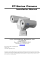
PT-Series Camera
Installation Manual
FLIR Commercial Systems, Inc.
70 Castilian Drive
Goleta, CA 93117
Phone: 888.747.FLIR (888.747.3547)
International: +1.805.964.9797
www.flir.com
Document Number: 427-0032-00-12
Version: 140
Issue Date: September 2010
This document is controlled to FLIR Technology Level 1. The information contained in this document pertains to a defense article controlled for
export by the International Traffic in Arms Regulations (ITAR). FLIR trade secrets contained herein are subject to disclosure restrictions as a matter
of law. Diversion contrary to US law is prohibited. US Government authorization for public release has been obtained from the Office of Security
Review, authorization No. 10-S-3394. Additional US Department of State authorization is not required prior to export or transfer to foreign
persons or parties, unless otherwise prohibited.
—
PT-Series Installation Manual
© FLIR Commercial Systems, Inc., 2010. All rights reserved worldwide. No parts of this
manual, in whole or in part, may be copied, photocopied, translated, or transmitted to any
electronic medium or machine readable form without the prior written permission of FLIR
Commercial Systems, Inc.
Names and marks appearing on the products herein are either registered trademarks or
trademarks of FLIR Commercial Systems, Inc. and/or its subsidiaries. All other trademarks,
trade names, or company names referenced herein are used for identification only and are the
property of their respective owners.
This product is protected by patents, design patents, patents pending, or design patents
pending.
The PT-Series thermal imaging system is controlled by US export laws. There are special
versions of this system that are approved for international distribution and travel. Please
contact FLIR Systems if you have any questions.
FLIR Commercial Systems, Inc.
70 Castilian Drive
Goleta, CA 93117
Phone: +1.888.747.FLIR (+1.888.747.3547)
Document Number: 427-0032-00-12, Version 140
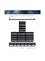
Document History
Revision
Date
Comment
100
February 2010
Initial Release
110
March 2010
Added FLIR Sensors Manager information
120
April 2010
Added IP66 and operating temperature to
specifications
130
May 2010
Added Level 2 export statement.
140
November 2010
Changed the power consumption specifications,
added inrush current specification, Export
version change.
This equipment must be disposed of as electronic waste.
Contact your nearest FLIR Commercial Vision Systems, Inc. representative for
instructions on how to return the product to FLIR for proper disposal.
This document is controlled to FLIR Technology Level 1. The information contained in this
document pertains to a defense article controlled for export by the International Traffic in Arms
Regulations (ITAR). FLIR trade secrets contained herein are subject to disclosure restrictions
as a matter of law. Diversion contrary to US law is prohibited. US Government authorization for
public release has been obtained from the Office of Security Review, authorization No. 10-S3394. Additional US Department of State authorization is not required prior to export or
transfer to foreign persons or parties, unless otherwise prohibited.
-ii
September 2010
427-0032-00-12, version 140
1
PT-Series Camera Installation
This manual describes the installation of the PT-Series cameras. If you need help during the
installation process, please call to speak with our support experts (877-773-3547).
This manual includes the following topics:
Installation Overview
Mounting the camera and its components
Connecting the electronics
For safety, and to achieve the highest levels of performance from the
PT-Series camera system, always follow the warnings and cautions in this manual when
handling and operating the PT-Series camera system.
1.1
Warnings and Cautions
WARNING!
If mounting the PT-Series camera on a pole, tower or any elevated location, use industry
standard safe practices to avoid injuries.
Caution!
Except as described in this manual, do not open the PT-Series camera for any reason.
Disassembly of the camera (including removal of the cover) can cause permanent damage
and will void the warranty.
Be careful not to leave fingerprints on the PT-Series camera’s infrared optics.
The PT-Series camera requires a power supply of 24 Volts. Operating the camera outside of
the specified input voltage range or the specified operating temperature range can cause
permanent damage.
When lifting the PT-Series camera use the camera body and base, not the tubes.
Note
427-0032-00-12, version 140
September 2010
1-1
1—PT-Series Camera Installation
1.2
PT-Series Installation Manual
Installation Overview
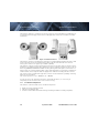
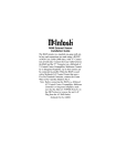
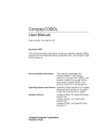
The PT-Series Camera is a multi-sensor camera system on a pan/tilt platform. Combinations of
an infrared thermal imaging camera and a visible-light video camera are intended for outdoor
installations.
Figure 1-1: PT-Series Camera
The PT-Series camera is intended to be mounted on a medium-duty fixed pedestal mount or wall
mount commonly used in the CCTV industry. Cables will exit from the back of the camera
housing. The mount must support up to 45 lbs. (20 KG).
The PT-Series camera is both an analog and an IP camera. The video from the camera can be
viewed over a traditional analog video network or it can be viewed by streaming it over an IP network using MPEG-4, M-JPEG and H.264 encoding. Analog video will require a connection to a
video monitor or an analog matrix/switch. The IP video will require a connection to an Ethernet
network switch, and a computer with the appropriate software for viewing the video stream.
The camera can be controlled through either serial or IP communications providing streaming
video over an IP network.
The camera operates on 21 - 30 VAC or 21 - 30 VDC.
In order to access the electrical connections and install the cables, it is necessary to
temporarily remove the back cover of the camera housing.
1.3
Installation Components
The PT-Series camera includes these standard components:
1-2
Multi-sensor Pan/Tilt Camera Unit
FLIR Sensors Manager CD
PT-Series Camera Documentation Package (including installation mounting templates)
September 2010
427-0032-00-12, version 140
PT-Series Installation Manual
1—PT-Series Camera Installation
The installer will need to supply the following items, the lengths of which are specific to the
installation.
Electrical wire, for system power. Refer to paragraph 1.7 “Electrical Connections and
Schematics” on page 1-5 for additional information)
Camera grounding strap
Coaxial RG59U video cables (BNC connector at the camera end) for analog video
Shielded Category 6 Ethernet cable for control and streaming video over an IP network; and
also for software upgrades.
Optional serial cable for serial communications.
Miscellaneous electrical hardware, connectors, and tools
1.4
Location Considerations
The camera will require connections for power, communications (IP Ethernet, and/or RS232/
RS422}, and video (two video connections may be required for analog video installations).
Important Note
Install all cameras with an easily accessible Ethernet connection to support future software
upgrades.
Refer to paragraph 1.7 “Electrical Connections and Schematics” on page 1-5 for interconnect
diagrams showing system configurations.
Ensure that cable distances do not exceed the Referenced Standard specifications and adhere
to all local and Industry Standards, Codes, and Best Practices.
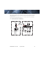
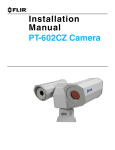
Not to scale
All dimensions in inches
Maximum exclusion cylinder
(Ø25.5” x 17.4” high)
Figure 1-2: PT-Series Pan and Tilt Exclusion Zone
427-0032-00-12, version 140
September 2010
1-3
1—PT-Series Camera Installation
1.5
PT-Series Installation Manual
Camera Mounting
Caution!
When lifting the PT-Series camera use the camera body and base, not the tubes.
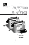
PT-Series cameras must be mounted upright on top of the mounting surface, with the base
below the camera. The unit should not be hung upside down.
2X 2.72 ± .02
Not to scale
All dimensions in inches
2X 2.72 ± .02
The PT-Series camera can be secured to the mount with four 5/16 or M8 bolts, as shown
below.
0
4X Ø.354 THRU
2X 3.19 ± .02
0
Tilt Axis
0.28
2X 3.19 ± .02
Pan Axis
Figure 1-3: PT-Series Camera Mounting
Once the mounting location has been selected, verify both sides of the mounting surface are
accessible.
Important Note
Connect and operate the camera as a bench test at ground level prior to mounting the
camera in its final location.
Use a thread locking compound such as Loctite 242 or equivalent with all metal to metal
threaded connections.
Using the template supplied with the camera as a guide, mark the location of the holes for
mounting the camera. If the template is printed, be sure it is printed to scale so the dimensions
are correct.
Once the holes are drilled in the mounting surface, install four (4) 5/16 or M8 bolts through
the base of the camera.
1-4
September 2010
427-0032-00-12, version 140
PT-Series Installation Manual
1.6
1—PT-Series Camera Installation
Prior to Cutting/Drilling Holes
When selecting a mounting location for the PT-Series camera, consider cable lengths and cable
routing. Ensure the cables are long enough given the proposed mounting locations and cable
routing requirements.
Use cables that have sufficient dimensions to ensure safety (for power cables) and adequate
signal strength (for video and communications).
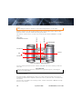
1.7
Electrical Connections and Schematics
Serial Communications
and Main Analog Video
IP Communication, Auxiliary
Analog Video, and Power
Video
RS232/RS422
Video
Ethernet
24
VAC/DC
24
VAC/DC
3/4” NPT for Cable
Gland or Conduit
Local
GND
16 AWG Shielded
Back Cover
16 AWG Shielded
20 AWG MAX
5 4 3 2 1
3
2
1
24 VAC/DCEarth Ground
24 VAC/DC+
Outputs
from camera
Inputs
to camera
Gland B Camera End
Gland A Camera End
427-0032-00-12, version 140
Male
BNC
Auxiliary
Port
3
2
1
Ethernet
24 VAC/DCEarth Ground
24 VAC/DC+
TX+
GND
RX+
RS422 Signals
Male
BNC
Main
Port
{
{
RS232 Signals
TD(B)+
TD(A)GND
RD(B)+
RD(A)-
Chassis
GND
September 2010
1-5
1—PT-Series Camera Installation
1.8
PT-Series Installation Manual
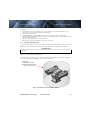
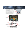
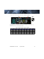
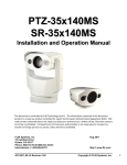
Removing the Back Cover
Use a cross-tip screwdriver to loosen the six
captive screws and remove the cover, exposing
the connections at the back of the camera. There
is a black grounding wire connected between the
case and the back cover
Ensure the camera is properly grounded. Typical
to good grounding practices, the camera chassis
ground should be provided using the lowest
resistance path possible. FLIR requires using a
grounding strap anchored to the grounding lug on
the back plate of the camera housing and
connected to the nearest earth-grounding point.
Ground
Lug
Cable
Gland A
Cable
Gland B
Not used
Serial Connector
for local control
IP Network
Analog Video
(monitoring output only)
Not used
Analog Visible Video
20 AWG MAX
5 4 321
Ethernet
BNC
Main
RCA
BNC
Auxiliary
Camera Power
Serial Connection
for local control
24 VAC/DC
Earth Ground
24 VAC/DC
Heater Power
Analog Infrared Video
Figure 1-4: PT-Series Camera Connections
1-6
September 2010
427-0032-00-12, version 140
PT-Series Installation Manual
1.9
1—PT-Series Camera Installation
Connecting power
The camera itself does not have an on/off switch. Generally the PT-Series camera will be
connected to a circuit breaker and the circuit breaker will be used to apply or remove power to
the camera. If power is supplied to it, the camera will be in one of two modes: Booting Up or
Powered On.
The power cable supplied by the installer must use wires that are sufficient size gauge (16
AWG recommended) for the supply voltage and length of the cable run, to ensure adequate
current carrying capacity. Always follow local building codes!
Note
The terminal blocks for power connections will accept a maximum 16 AWG wire size.
1.10 Video Connections
The analog video connections on the back of the camera are BNC connectors.
The video cable used should be rated as RG59U or better to ensure a quality video signal.
1.11 Ethernet Connection
The cable gland seal is designed for use with Shielded Category 6 Ethernet cable.
427-0032-00-12, version 140
September 2010
1-7
1—PT-Series Camera Installation
PT-Series Installation Manual
1.12 Serial Connections
The camera supports RS-422 and RS-232 serial communications using common protocols
(Pelco D, Bosch). For configuration settings see paragraph 1.13 “Setting Configuration Dip
Switches” on page 1-9.
Note
The terminal blocks for serial connections will accept a maximum 20 AWG wire size.
1.12.1 Pelco D Commands for PT-Series
Standard Commands
Tilt Up
Tilt Down
Pan Left
Pan Right
Pan/Tilt UpLeft
Pan/Tilt UpRight
Pan/Tilt DownLeft
Pan/Tilt DownRight
Stop
Focus Near
Focus Far
Zoom In
Zoom Out
Pelco Command
Command
Aux 1 on
FF 01 00 09 00 01 0B
Black Hot
Aux 1 off
FF 01 00 0B 00 01 0D
White Hot
Aux 2 on
FF 01 00 09 00 02 0C
Active=DLTV
Aux 2 off
FF 01 00 0B 00 02 0E
Active=IR
Aux 3 on
FF 01 00 09 00 03 0D
Toggle Plateau Values
Aux 3 off
FF 01 00 0B 00 03 0F
Toggle AGC Type
Aux 4 off
FF 01 00 0B 00 04 10
IR FFC
Aux 5 off
FF 01 00 0B 00 05 11
Toggle LUT Pallette
Aux 6 on
FF 01 00 09 00 06 10
Toggle DDE Gain
Aux 6 off
FF 01 00 0B 00 06 12
Toggle AGC ROI
Aux 7 on
FF 01 00 09 00 07 11
Toggle:MID ITT
Aux 7 off
FF 01 00 0B 00 07 13
Toggle Max Gain
Table 1-1: Pelco D AUX Structure
Byte 1
Byte 2
Byte 3
Byte 4
Byte 5
Byte 6
Byte 7
Sync Byte
Address
Command 1
Command 2
Data 1
Data 2
Checksum
FF
Desired Pelco
Address
00
09/0B =
On/Off
00
AUX #
Hex Sum of
Bytes 2-6
1-8
September 2010
427-0032-00-12, version 140
PT-Series Installation Manual
1—PT-Series Camera Installation
1.13 Setting Configuration Dip Switches
The figure below shows the locations of dip switches SW102 and SW103.
SW102
SW103
Switch
Position
Off
On
Figure 1-5: PT-Series Camera Configuration
Pelco Address: This is the address of the system when configured as a Pelco device. The
available range of values is from decimal 0 to 255.
Table 1-2: Dip Switch Address/ID Settings—SW102
ID
Bit 1
Bit 2
Bit 3
Bit 4
Bit 5
Bit 6
Bit 7
Bit 8
0
OFF
OFF
OFF
OFF
OFF
OFF
OFF
OFF
1
ON
OFF
OFF
OFF
OFF
OFF
OFF
OFF
2
OFF
ON
OFF
OFF
OFF
OFF
OFF
OFF
3
ON
ON
OFF
OFF
OFF
OFF
OFF
OFF
…
…
…
…
…
…
…
…
…
255
ON
ON
ON
ON
ON
ON
ON
ON
427-0032-00-12, version 140
September 2010
1-9
1—PT-Series Camera Installation
PT-Series Installation Manual
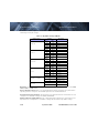
Power Board Switch Layout and Control: The tables below defines the switch locations, bit
numbering and on/off settings.
Table 1-3: Dip Switch Settings—SW103
Switch octaves
Baud rate
Protocol
Serial Com
Preset
Settings
Description
Bit 1
Bit 2
OFF
OFF
2400
ON
OFF
4800
OFF
ON
9600
ON
ON
19200
Bit 3
Bit 4
OFF
OFF
Pelco-D
ON
OFF
NA
OFF
ON
Bosch
ON
ON
NA
Bit 5
Bit 6
OFF
OFF
NA
ON
OFF
RS422
OFF
ON
RS232
ON
ON
N/A
Bit 7
Bit 8
OFF
OFF
Section1
ON
OFF
Section2
OFF
ON
Section3
ON
ON
Section4
Bit 9
Hardware/~Software
OFF
Software select
ON
Hardware select
Bit 10
Not Used
X
Baud Rate: This is the baud rate of the system user serial port. The available values are 2400,
4800, 9600, 19200 kbaud.
Camera Control Protocol: This is the communication protocol selected for the system when
operating over the serial port. The available protocols are Pelco-D and Bosch.
Serial Communication Standard: This determines the electrical interface selected for the user
serial port. The available settings are RS422 and RS232.
Software Override of DIP Switches: This setting determines whether the system will use the
dip switches for configuration or if software settings will override the dip switch settings.
1-10
September 2010
427-0032-00-12, version 140
PT-Series Installation Manual
1—PT-Series Camera Installation
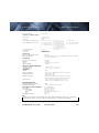
1.14 PT-Series Camera Specifications
Camera Platform Type
PT Multi-Sensor
THERMAL CAMERA SPECS
Detector Type
Long-Life, Uncooled
VO× Microbolometer
Pixel Pitch
25 μm
Focal Length (lens/model dependent)
9 mm, 13 mm, 19 mm
9 mm, 13 mm, 19 mm,
35 mm, 65 mm, 100 mm
21.5 mm, 35 mm
Field Of View (lens/model dependent)
24° × 20° (PT-124; 9 mm)
17° × 14° (PT-117; 13 mm)
12° × 10° (PT-112; 19 mm)
48° × 39° (PT-348; 9 mm)
34° × 28° (PT-334; 13 mm)
24° × 19° (PT-324; 19 mm)
13 °× 10° (PT-313; 35 mm)
7° × 5° (PT-307; 65 mm)
4.6° × 3.7° (PT-304; 100 mm)
41° × 33° (PT-641; 21.5 mm)
26° × 21° (PT-626; 35 mm)
Zoom (model dependent)
2× E-zoom
2× & 4× E-zoom
Spectral Range
Focus Range
Athermalized, focus-free
OUTPUTS
Composite Video NTSC or PAL
Video Over Ethernet
Standard
Two independent channels of streaming MPEG-4, H.264, or M-JPEG
for each of two cameras.
CONTROL
Point To Point (stand alone)
Ethernet
Standard
Standard
Serial
Network Enabled
RS-232/-422; Pelco D, Bosch
Standard
PAN/TILT PERFORMANCE
Pan Angle/Speed
Tilt Angle/Speed
Continuous 360°; 0.1° to 70°/sec
+90° to -90°; 0.1° to 30°/sec
GENERAL
Weight
36 lb
Dimensions (L,W,H)
13.7” × 18.4” × 12.8” (348 mm × 467 mm × 326 mm)
Power Requirements
24 VAC (21-30 VAC)
24 VDC (21-30 VDC)
Power Consumption
24 VAC: 85 VA max no heater, 215 VA max w/heater
24 VDC: 65 W max no heater, 195 W max w/heater
Inrush Current
<10 A for DC power supply with slew rate > 10 ms
<38 A for AC power supply with slew rate > 4.17 ms
ENVIRONMENTAL
Dust, Water Protection Rating
IP66
Operating Temperature
-40°C to +55°C (-40°F to +130°F)
DAY/NIGHT CCD CAMERA
Sensor Type
Lens Field Of View
Focal Length
Zoom
F/#
Sony FCB-EX1010
1/4” Exview HAD CCD
57.8° (h) to 1.7° (h)
3.4 mm to 122.4 mm
36× Optical zoom, 12× E-zoom
1.6 to 4.5
Effective pixels (NTSC)
380,000
Note
Power consumption is independent of the input voltage when the heater is off. The power
drawn by the heaters increases with the input voltage to a maximum at 30 Volts.
427-0032-00-12, version 140
September 2010
1-11
1—PT-Series Camera Installation
1-12
PT-Series Installation Manual
September 2010
427-0032-00-12, version 140
2
Verify Camera Operation
Prior to installing the camera, use a bench test to verify camera operation and configure the
camera for the local network.
The camera provides analog video and can be controlled through either serial or IP
communications providing streaming video over an IP network.
2.1
Power and analog video
Step 1
Connect the power, video, and serial cables to the camera as described in paragraph
1.7 “Electrical Connections and Schematics” on page 1-5.
Step 2
Connect the video cable from the camera to a display/monitor and connect the
power cable to a power supply.
The camera operates on 21 - 30 VAC or 21 - 30 VDC.
Verify that video is displayed on the monitor.
Step 3
Connect the serial cable from the camera to a serial device such as a keyboard, and
confirm that the camera is responding to serial commands. For more information
about the supported serial commands, refer to paragraph 1.12 “Serial Connections”
on page 1-8.
2.2
IP Communications
As shipped from the factory, the PT-Series camera has an IP address of 192.168.250.116
with a netmask of 255.255.255.0.
Step 1
Configure a laptop or PC with another IP address from this network (for example,
192.168.250.1).
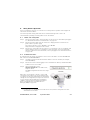
Step 2
Connect the camera and the laptop to the same Ethernet switch (or back-to-back with
an Ethernet crossover cable).1
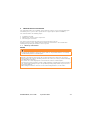
Step 3
Open a web browser, enter
http://192.168.250.116 in the address bar,
and press Enter.
The Web Configurator will start at the Login
screen.
When this screen appears, the PC is successfully
connected to the camera over the IP network. Prior
to logging in to the web configuration tool and making
changes to the configuration, it may be wise to bench
test the camera with the FLIR Sensors Manager
software using the factory configured IP address.
Refer to paragraph 2.3 “Using FLIR Sensors
Manager (FSM)” on page 2-2.
1. In some cases, a straight Ethernet cable can be used, because many PCs have auto
detect Ethernet interfaces.
427-0032-00-12, version 140
September 2010
2-1
2—Verify Camera Operation
2.3
PT-Series Installation Manual
Using FLIR Sensors Manager (FSM)
The following provides a brief description of how to use FSM to control a camera and stream
video from the camera. For more detailed information on how to use FSM, refer to the FLIR
Sensors Manager User Manual.
If the FSM software has not been installed yet, locate the CD that came with the camera and
install it on the PC.
2.3.1
Running FSM
Step 1
Run the FSM software by double clicking the icon on the desktop, or
click on the Windows Start button and select Programs > FLIR Sensors
Manager > FLIR Sensors Manager.
Initially the FLIR Sensors Manager splash screen will be displayed. The software
version may be different than the version displayed below.
2-2
September 2010
427-0032-00-12, version 140
PT-Series Installation Manual
2—Verify Camera Operation
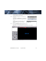
After a brief while, the FSM main window will appear, and a popup FSM Notification
window will appear in the lower right of the screen indicating that no cameras
(servers) have been discovered yet.
Step 2
Click on the Accept button to acknowledge the
notification.
The FLIR Sensors Manager uses a “client/server”
architecture. The FSM software is considered a
client, and the cameras are considered servers or
sensors.
The Sensors Panel in the upper right of the
window indicates no sensors have been
discovered and added to the list of Active
Sensors.
Step 3
Click on the Discovery button along the top of
the window to bring up the Discovery Panel. The
FSM software can automatically discover FLIR cameras on the network.
Click
427-0032-00-12, version 140
September 2010
2-3
2—Verify Camera Operation
PT-Series Installation Manual
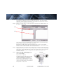
Step 4
When the Discovery Panel is displayed, click Refresh.
The FLIR camera will appear in the list of Discovered Servers. The camera will be
called “flir”, and the asterisk in parenthesis “(*)” indicates the camera has not been
added to the list of Active Servers on the right.
Step 5
Click on the center bar “>” to move the camera over to the list of Active Servers on
the right as shown below.
Click
Click
Once the camera has been added to the list of Active Servers, you can click on the
Discovery button again to close the Discovery Panel.
By default, the FSM software will automatically discover sensors in the network,
connect to the first camera it finds, take control of the camera, and display the video
from the camera in Video Wall 0 on the main FSM window.
Step 6
Confirm that video is streamed to the monitor and it is possible to control the camera
using the zoom controls and so on. For example, click on the zoom button (magnifying
glass with +), and the video will zoom to 2X. Once operation of the camera has been
confirmed, the camera can be configured to an IP address that matches the
installation network.
Step 7
Return to the Web Configurator screen
shown at the right and enter basic as the
User and click Login.
No password is required.
The Web Configurator will display the Help
screen listing information on the camera’s
software and hardware configuration.
The menu on the left allows you to select
various configuration web pages in order to
set the camera parameters. See “PT-Series
Configuration” on page 2-5.
2-4
September 2010
427-0032-00-12, version 140
PT-Series Installation Manual
2.4
2—Verify Camera Operation
PT-Series Configuration
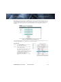
After logging in, the Help screen is displayed. This screen has information about the camera
including hardware and software revision numbers, part numbers, and serial numbers. If you
need to contact FLIR for support, this information will be useful to the support engineer. Use
the Menu entries at the left of the screen shown in Figure 2-1 to configure the PT-Series
camera.
Figure 2-1: Web Configurator Help Screen
The following paragraphs show the pages for setting serial communication parameters and
setting a new IP address for a camera on a local area network.
Serial Remote
Step 1
Click Serial Remote. The screen at
the right will be displayed.
Step 2
Enter the parameters for your serial
control configuration.
The settings you make in this screen
will only become active when the
hardware/software DIP switch is set
to allow software settings to override
the dip switch settings. Refer to
paragraph 1.13 “Setting
Configuration Dip Switches” on page
1-9.
427-0032-00-12, version 140
September 2010
2-5
2—Verify Camera Operation
PT-Series Installation Manual
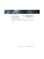
Lan Settings
Step 1
Click LAN Settings. The screen
at the right will be displayed.
Step 2
Enter the Hostname, Gateway,
IP Address, and Netmask that
are appropriate for the local
area network. Then click Save.
A message will appear indicating the IP address has been changed and the browser
will no longer be able to communicate with the camera. You must connect the camera
to an appropriate local area network (LAN) and connect to the camera using its new
IP address.
2-6
September 2010
427-0032-00-12, version 140
A
Mechanical ICD Reference
The following Mechanical Interface Control Document detail the outline and mounting for the PTSeries cameras. These documents are provided for reference only. You should consult your
local sales representative or application engineer to obtain current ICD information. Also, the
PT-Series Thermal Imaging Camera Core Data Sheet available from the website contains
important mechanical interface data as well.
427-0032-00-12, version 140
September 2010
A-1
A—Mechanical ICD Reference
A-2
PT-Series Installation Manual
September 2010
427-0032-00-12, version 140
PT-Series Installation Manual
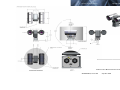
Appendix A
Appendix A—Mechanical ICD Reference
Mechanical ICD Reference
PT-Series Camera Mechanical Interface Control Document
427-0032-00-12, version 140
September 2010
Sheet 1
A-3