Download MANUAL

Transcript
H.264MP-PTZ RTSP Streaming User’s Manual
H.264 Main Profile RTSP Streaming
Stand Alone
PAN/TILT/ZOOM IP Camera
MANUAL
Firmware 2.2.1.8 Version
Revision Date: 2010.04.01
1
H.264MP-PTZ RTSP Streaming User’s Manual
WARNING: If the actions indicated in a “WARNING” are not complied with, injury
or major equipment damage could result. A warning statement typically
describes the hazard, its possible effect, and the measures that must be taken
to reduce the hazard.
CAUTION: If the action specified in the “CAUTION” is not complied with, damage
to your equipment could result.
NOTE: A “NOTE” provides supplementary information, emphasizes a point or procedure, or
gives a tip for easier operation.
CAUTION:
Any changes or modifications not expressly approved by the party responsible for
compliance could void the user’s authority to operate the equipment.
NOTE: This equipment has been tested and found to comply with the limits for a class digital device, pursuant
to part 15 of the FCC Rules. These limits are designed to provide reasonable protection against harmful
interference when the equipment is operated in a commercial environment. This equipment generates, uses,
and can radiate radio frequency energy and, if not installed and used in accordance with the instruction manual,
may cause harmful interference to radio communications. Operation of this equipment in a residential area is
likely to cause harmful interference in which case the user will be required to correct the interference at his own
expense.
Disposal of Old Electrical & Electronic Equipment
(Applicable in the European Union and other European countries with separate
collection systems)
This symbol on the product or on its packaging indicates that this product shall not be treated as
household waste. Instead it shall be handed over to the applicable collection point for the recycling of
electrical and electronic equipment. By ensuring this product is disposed of correctly, you will help prevent
potential negative consequences for the environment and human health, which could otherwise be caused
by inappropriate waste handling of this product. The recycling of materials will help to conserve natural
resources. For more detailed information about recycling of this product, please contact your local city
office, your household waste disposal service or the shop where you purchased the product.
2
H.264MP-PTZ RTSP Streaming User’s Manual
Must read all the safety and operating instructions below before operating the unit.
• Make sure not to connect the power before you have installed the camera.
• There is great chance to damage your camera if the camera is opened by an unqualified
service engineer or installer.
• Avoid using the camera under direct sunlight (tropical area, Middle East), or near to any
source of heat. Sun shielding recommended.
• Don’t submerge the camera into water; don’t install the camera upside down
• Avoid exposing the camera to violent movement or vibration.
• Must use proper “Relay” that will match with alarm output devices (High power spot light,
motors), never connect alarm output load > 0.5A directly to camera alarm out.
• Please use power adapter equipped with the camera, foreign power adapter with wrong
voltage may permanent damage your camera.
• Clean the glass dome bubble frequently to ensure good clear view, remove the snow and
ice accumulated outside and inside of class window shield, keep camera inside dry by hot
blow dryer.
• Must remove all cushions and lens cover inside dome bubble before power on.
WARNING:
Never put the 24V AC power adapter over 10 meters away from your camera.
Permanent damage will result due to voltage drop on longer wires.
Larger
current (due to lower voltage) will eventually burn your camera
3
H.264MP-PTZ RTSP Streaming User’s Manual
Table of Contents
Chapter 1 Features ................................................................................................................... 5
Chapter 2
Packing Detail .......................................................................................................... 7
Chapter 3 Cable and Connectors .............................................................................................. 8
3.1 Tail Wire Connectors ......................................................................................................................... 8
3.2 Optionals ......................................................................................................................................... 11
Chapter 4 System Requirement .............................................................................................. 14
4.1 The lowest hardware configuration .................................................................................................. 14
4.2 The recommended hardware configuration ..................................................................................... 14
Chapter 5 INSTALLATION ...................................................................................................... 15
5.1 CONNECT to PC or LAN .............................................................................................................. 15
5.2 CONNECT to WAN ....................................................................................................................... 20
5.3 Install ActiveX and Login ............................................................................................................... 21
Chapter 6 Software Configurations ......................................................................................... 27
6.1 Menu Tree ..................................................................................................................................... 27
6.2 Live View Page ............................................................................................................................. 28
6.3 Video Playback ............................................................................................................................. 32
6.4 System Settings ............................................................................................................................ 34
6.5 Video Settings ............................................................................................................................... 36
6.6 Motion Alarm Setting ..................................................................................................................... 38
6.7 Sensor Alarm Settings .................................................................................................................. 39
6.8 Network Setting............................................................................................................................. 41
6.9 Advanced Settings ........................................................................................................................ 44
6.10 User Management ...................................................................................................................... 47
6.11 RS-485 Settings .......................................................................................................................... 48
6.12 Storage Settings.......................................................................................................................... 49
6.13 Local Settings ............................................................................................................................. 53
Appendix 1
Network Port for IP Camera ................................................................................. 54
Appendix 2
Network Factory Defaults ..................................................................................... 54
Appendix 3
DDNS introduction ............................................................................................... 54
Appendix 4
FAQ ...................................................................................................................... 57
Appendix 5
Speed Dome Setup .............................................................................................. 61
Appendix 6
Cross Ethernet Cable Making Tip ........................................................................ 72
4
H.264MP-PTZ RTSP Streaming User’s Manual
Chapter 1
Features
H.264 Main Profile Encoding, Duplex Audio
Clairvoyant IP Speed Dome Cameras offer cost-effective outdoor IP surveillance solution for
remote monitoring and stand alone alarming over a local area network or the Internet. Only
standard UTP Cat. 5e Ethernet cable is required carrying both Video & audio in network data
packets, Clairvoyant IP Speed Dome Cameras are ideal for use in small or mid-sized
businesses and homes, it is also easy to set up and use.
Clairvoyant IP Speed Dome Cameras are embedded IP based smart devices designed for
network video/audio surveillance applications. Optimized H.264 main profile video
compression algorithm assures clearer and more fluent image transmission. The Clairvoyant
IP Speed Dome Camera adopts Sony 18 or 36X zoom camera, the latest technology and
high integration single chip SOC with powerful Linux RTOS (Real-time Operating System) to
realize high performance and low cost digital multimedia processing. Built-in Web Server
allows users to conveniently carry out remote control via Internet Explorer. Furthermore,
central management software can be used for integrated surveillance and management of
multiple Clairvoyant IP Speed Dome Cameras, very easy to build large surveillance system.
Performance:
- Outdoor PTZ mechanism integrated with 80 pcs Ф10mm high power IR LEDs.
- SOC single chip solution, equipped with two processors, ARM9 and DSP
- H.264 main profile @ Level 3, realize transmission of High Definition video over low
network bandwidth easily.
- Support dual compression and dual video streams, more adaptive to different network
environment, display different resolution video on different client devices (PC & phone)
- Up to 30 frames per second in all resolutions ranging up to 704 x 576
- Up to 10 viewers can directly access the camera simultaneously
- Stand alone alarming & motion detection; able to set 4 detective zones each with 5 levels
sensitivity, send snapshots by scheduling or at alarm/ motion detected through emails or
upload pictures to FTP server.
- Built-in Web server enables the use of a standard Web browser for viewing and
management
- Support remote software upgrade safely function
- Support dynamic IP address (DDNS), LAN, Internet (ADSL PPPoE & DHCP)
- Network protocols: HTTP, TCP/IP, UDP, RTP, RTCP, RTSP, SMTP, PPPoE, DDNS, DNS,
SMTP, BOOTP, DHCP, FTP, NTP, UPnP, Multicast
- Support Bi-directional real time transmission of audio talk-back & broadcast.
- Network self-adapting technology to adjust video frame rate automatically according to the
network bandwidth.
- Auto-recovery function if exception occurs and auto-connection if the network fails
- Provide SDK and client demo source code.
- Management software that can manage up to 1728 cameras in 48 groups, display
maximum 36 cameras video on single screen, support video lost、motion detection and
sensors alarm functions
- Support masks function to mask sensitive area to protect privacy.
5
H.264MP-PTZ RTSP Streaming User’s Manual
- Support active & passive mode access, support GSM/ CDMA network or private network
without public IP.
- Support Multicast, unlimited clients connection. (match with Clairvoyant decoder or
NVSCenter software)
- Supports TF card up to 32GB; can store recording and snapshots locally.
- IP66 Weather proof
Technical parameters:
Imagine Sensor: Sony FCB-EX480C(P) ; FCB-EX1010(P)
Night Vision: Built-in 80 pcs Ф10mm high power IR LEDs, car plate viewable at 80-100
meters distance
PAN & TILT: 360º continuous PAN, 180º TILT/ auto flip over
Manual Speed: 0.1/S ~ 100°/S
Preset Speed: 240°/S
Swing : scan speed: 10°~30°/S
Cruising : 8 point to point scan routes, 8 patrol routes, 4 auto learning plans
Masks : 8 privacy masks
Video compression: H.264 main profile @Level 3; M-JPEG dual compression
Video Resolution: PAL: 352x288(CIF),704x288(2CIF),704x576(D1)
NTSC: 352x240(CIF),704x240(2CIF, 704x480(D1)
Adjustment of Video Parameters: Brightness, hue, contrast, saturation and image quality
Streaming Format: Optional streaming format (video streaming or audio & video streaming)
Video Frame Rate: PAL: 1 - 25 frames/second; NTSC: 1 - 30 frames/second
Video Compression Bit Rate: 16Kbit/S~16Mbit/S, constant bit rate or variable bit rate
Audio Input: 1 channel linear input, Impedance: 1kΩ
Audio Compression: MP3
Audio Output: 1 channel linear output
Audio talk-back input: 1 channel, MIC interface
Supported Protocols: HTTP, TCP/IP, UDP, RTP, RTCP, RTSP, SMTP, PPPoE, DDNS,
DNS, SMTP, BOOTP, DHCP, FTP, NTP, UPnP, Multicast
System Interface: 10 Base-T/100Base-TX Ethernet port; 1 RS485 port, 1 RS232 port;
Alarm Input: 1 channel on/off input, supporting NO (normally open) or NC (normally close)
Alarm Output: 1 channel on/off output, Contact rating 220VAC 1A/ 24VDC 1A
Dimensions (diameter, height) : 7”, 10”
Weight (Kgs): 8.5
Input Power Supply: DC 24V 3A
Maximum Power: Less than 50W
Operating Temperature: -10 ~ +55 ℃
Storage Temperature: -20 ~ +70 ℃
Weather Proof: IP66
System Requirements:
Operation System:
Microsoft Windows XP, VISTA, Windows 7
Browser:
Microsoft Internet Explorer 6.x or above
6
H.264MP-PTZ RTSP Streaming User’s Manual
Chapter 2
Packing Detail
1. IP Speed Dome Camera
2. Installation Software utilities CD
3. AC Adaptor & Power Cord
1. IP Speed Dome Camera
2. Installation Software utilities & Central Management Software CD
3. AC Adaptor (AC24V/ 3A) & Power Cord
WARNING:
Never put the 24V AC power adapter over 10 meters away from your camera.
Permanent damage will result due to voltage drop on longer wires.
Larger
current (due to lower voltage) will eventually burn your camera
7
H.264MP-PTZ RTSP Streaming User’s Manual
Chapter 3
Cable and Connectors
3.1 Tail Wire Connectors
1. Terminal (A+/ B-) : RS-485 A+/ B-; D+/ D- to control PTZ
2. Reset Terminal : Restore to factory default settings (short the two terminal at power on)
3. RCA connector : Female audio output to speaker
4. Power connector : DC12V/ 2A
5. RCA plug : Male audio input port to sound monitor/ microphone.
6. Terminals (Alarm) : Alarm input (NC or NO) /
Alarm output ( on/off output, 220VAC 1A/ 24VDC 1A)
7. RJ-45 : Network Ethernet connector, LEDs flashing when accessing
Note:
After “Reset” Please must notice you must set your computer IP to 192.168.55.xxx, for example
192.168.55.20 so that you can connect the camera after reset (restore to factory default IP
192.168.55.160), must remember to disable wireless adapter or set wireless IP to different subnet (from
wired IP), before performing other necessary settings.
WARNING: Unpacking
Please must ask user to remove cushion inside dome bubble, clear warning
messages on top of dome bubble (also in user's manual) indicates don't
power on before remove all cushion, or may damage the camera.
8
H.264MP-PTZ RTSP Streaming User’s Manual
Connect mount bracket to speed dome
9
H.264MP-PTZ RTSP Streaming User’s Manual
WARNING: Must use DC 12V for microphone
Please notice It’s AC 24V power for Speed dome camera, never mix up power
supply with microphone. Wrong power will burn microphone.
10
H.264MP-PTZ RTSP Streaming User’s Manual
3.2 Optionals
Port Name
Description
1 RSMA Connector
○
2 Tail Cable
○
Detachable 5 dBi omni antenna
Optional high gain directional antenna
3 feet wire
Connect BNC output to monitors
RS-485 port can be used to connect the external PAN/ TILT Seat
No
1
2
DESCRIPTION
485A(TX+)
485B(TX-)
RS485:Transmit data
RS485: Receive data
Connect Pan/ Tilt Seat D+, D- : Connect PT control line (485A, 485B terminal)
11
H.264MP-PTZ RTSP Streaming User’s Manual
Alarm input:
Connect sensors that support on/off states change.
To connect the Active Infrared Sensor to IP CAMERAR camera ALARM IN, will trigger alarm
when light beams interrupted.
12
H.264MP-PTZ RTSP Streaming User’s Manual
Alarm output:
WARNING: If connect higher power loading (> 1A) directly to camera alarm out
will cause damage the camera.
Higher current (>0.5A) will accelerate aging of the relay on camera PCB,
external relay box is always recommended to protect the camera.
13
H.264MP-PTZ RTSP Streaming User’s Manual
Chapter 4
System Requirement
4.1 The lowest hardware configuration
.◆CPU: Intel Pentium 2.0GHz (Don’t support AMD CPU)
◆Memory:1,024MB
◆Graphics Card: TNT2
◆Sound Card: Speaker, Microphone
◆Hard Disk: Recording Image,no less than 40G
4.2 The recommended hardware configuration
.
◆CPU: Intel Core2 DUAL 2.0GMhz or above
◆Memory: 2,048MB
◆Graphics Card: Nvidia Geforce FX9400 or ATI RADEON 9000 series 256MB video
memory, graphic card supports hardware Scaling
The PC graphics card must support hardware zoom in & out.
Tested Graphics Cards are as follow:
•
•
•
•
•
Nvidia TNT/ TNT2,
Geforce GTX295/285; Fx 8800/ 9600/ 9800 and its series;
ATI Radeon 7000/7200/7500/8500/9550/9600/9700/9800 and X & HD series,
Matrox G450/ 550;
INTEL 865G/ 875G and its series.
Operation System
◆Chinese; English: Windows2000/ Windows XP/ Windows Vista/ Windows 7.
Software
◆IE 6.0 or above
◆DirectX 8.0 or above
◆TCP/IP protocol
14
H.264MP-PTZ RTSP Streaming User’s Manual
Chapter 5
INSTALLATION
5.1 CONNECT to PC or LAN
CAUTION:
Please use the DC power adapter that is provided with the camera.
Connecting camera to other power source will cause permanent damage
to the camera.
NOTE:
Please use straight Ethernet cable (CAT. 5e) to connect camera to your home/ office
network switch/ hub or a broadband router.
For Wi-Fi models, you will still need to connect camera to your PC by Ethernet cable at
first time installation, correct SSID, WEP/ WPA password & IP address must be set
before you can connect the camera wirelessly (See more in section 6.8 Network
Settings).
You will see two IP address by camera search software utility, if you didn’t remove the
Ethernet cable before the camera wireless connection.
15
H.264MP-PTZ RTSP Streaming User’s Manual
Click “Search Camera” on Utility CD auto-play menu*, will find all the Clairvoyant IP cameras in
your local network.
* To use SearchNVS software to search and modify network parameters (IP address, Subnet
mask, Gateway etc.).
NOTE:
A: Find the SearchNVS.exe in 【tool software】 folder of Utility CD and copy it to PC.
B: Install the Central Management software first, follow below steps to find the SearchNVS:
【Start】---【all programs】--- 【NVS Center500】---【Search NVS】.
The factory default settings of the IP Camera are as follows
IP: 192.168.55.160; Subnet mask: 255.255.255.0
User name: admin; Password: admin
Run the SearchNVS software to search and modify IP Camera network parameters.
SearchNVS use multicast protocol to find Clairvoyant IP cameras; most firewalls forbid the
multicast data packets. So please close the firewall first or enable/ allow SearchNVS to use
multicast protocol.
Click on【Search】button to start search IP Cameras as illustrated below:
【Local IP 】Display the local PC IP. If your PC has multiple NICs or multi-addressed local IP,
please select an IP address to connect NVS.
In the above Search NVS software interface, it shows this computer has searched all IP
Cameras in LAN. If there are many IP cameras in your LAN, you can distinguish which
camera is yours by the Device Name based on the unique device ID. The Device Name
was named in the factory as “DVS+ID number”.
Note:
Please make sure there is DHCP server available, or set your PC IP address
manually. Your PC won’t “Obtain an IP address automatically” without DHCP connected.
SearchNVS won’t work on a PC without IP address.
Please select the correct Network Interface Card (that connected to cameras) IP address
for “Local IP” if you have multiple Network Interface Cards installed in your PC.
Set IP address for IP camera.
Your computer IP address must be “in the same subnet” of IP Camera in order to visit
IP camera. So we need to set the IP address of the IP camera before accessing
camera.
To get your PC IP configuration information: go to command mode by click 【Start】
【Run】”, then input “command” or “cmd”(Windows 2000/XP system).click “ok”:
16
H.264MP-PTZ RTSP Streaming User’s Manual
Type “ipconfig” at command prompt”, press “Enter” button, you will get your PC
Network Interface Card IP address/ Subnet mask/ Gateway information.
17
H.264MP-PTZ RTSP Streaming User’s Manual
Please remember the IP Address,Subnet Mask, Default Gateway,then setup the IP Camera
IP address according to your PC IP address to ensure computer & IP Camera IP
addresses are “in the same subnet” .
For example : Set IP Camera IP addresses to 192.168.1.100. Default Gateway & Subnet
Mask same as PC.
Click 【Set】to set “Network Parameter” as illustrated below:
Modify relative Network Parameters; click “OK”, then the IP camera will reboot.
Test the IP camera connection: go to command mode by click 【Start】---【Run】”, then
input “command” or “cmd” (Windows 2000/XP system).click “ok”,
Type “ping 192.168.1.100” at command prompt, press “Enter” button, you will get following
information:
The message shown on above indicates the IP Camera is functioning normally and connects to
18
H.264MP-PTZ RTSP Streaming User’s Manual
same subnet (LAN) correctly. If the screen displays other information, please confirm the IP
address settings and check the network cables again.
Warning:
Please consult your office network administrator to get a free IP for your
IP Camera; duplicated IP address will cause undesired problems.
CAUTION:
Please always write down the password and keep password in safe place.
Please kindly notice, if you forget password you set, you will have to
return the camera to manufacturer for recovery, there is no way to reset
password of your camera.
19
H.264MP-PTZ RTSP Streaming User’s Manual
5.2 CONNECT to WAN
Connect IP Camera to your broadband
router or NAT gateway.
Do the following setup:
1. Setup Virtual Server/ forward port on
your router to camera,
2. or set your Camera IP to router DMZ
3. Obtain DDNS service from mvDDNS if
you don’t have fixed public IP,
4. Setup DDNS account information to
your camera
5. Access camera URL through Internet.
Example:
http://your_camera.myddns.net:port
Please reference more details of Router
& mvDDNS setup on Reference User’s
Manual.
Note:
Clairvoyant IP cameras/ Video servers support PPPoE auto-dial-up, that you can connect
your camera directly to an ADSL modem; please remember to setup DDNS and email
parameters before you enable PPPoE function.
It's impossible to access “LAN IP” from Internet; IP started with 192.168.xxx.xxx is LAN IP.
LAN IP sometime called illegal IP, only legal “Public IP” can be accessed through Internet.
It’s not possible to access your LAN IP through Internet or you will be in big security threat,
Hackers can access your bank account information and secrets stored in your LAN PC
You will need to connect IP camera Internet before you can access from remote through
Internet, there shall be a “Gateway” connect your office network (LAN) to Internet (WAN),
usually it is a broadband router, you will need to change settings of your broadband router to
enable the accesses from Internet to your camera.
Connect IP camera Internet:
1. Port Forwarding: forward port 80 & 5000 (default web & data port, see your router manual
or Appendix 4 FAQ)
2. Set DNS & Gateway settings of your camera
3. Register a ne w DDNS account for DDNS Service, Set DDNS settings of your camera.
20
H.264MP-PTZ RTSP Streaming User’s Manual
Note:
a. Broadband router is firewall in nature will block all accesses from Internet, you will need to
set virtual server (port forwarding) on your router, normally we will always suggest to use port
80 or port > 1024 for web port to avoid conflicts, port <1024 are frequently used by other
applications.
b. Check if the DNS & Gateway settings are correct, it is impossible to get out of your LAN if
wrong. (Gateway is the door, DNS is like "map", people won't go out home without knowing
where the door is or don't have map to find the way)
c. Always test the DDNS service from remote IP (that is outside of your LAN); some router will
block WAN port access from inside LAN.
The broadband router that connect Internet is similar to a "Security Guard" at the entrance of
LAN (Local area network), who will protect you from un-authorized intrusions from outside
(Internet), IP cameras located in LAN are well protected so that accesses from outside
(Internet) are not possible to pass router "Guard".
Remote viewer won't be able to access
IP cameras behind router "Guard" from outside (Internet), unless you have gave the correct
"commands", letting router "Guard" to allow outsiders access the cameras in LAN.
The correct "commands" are so-called "Virtual Server" or "Port Forwarding" settings on
various routers, please reference the routers user's manual to learn how to enable "Virtual
Server" http port & data port (default are: 80 & 5000) on your router. ( "Port Forwarding" =
mapping WAN http port & data port (default are: 80 & 5000) to LAN IP address & ports )
Please see Appendix 4 FAQ for more details.
5.3 Install ActiveX and Login
1. Install “OCX setup”, ActiveX controls (plug-in) required by IE browser is installed
simultaneously (click on the “Install 1st” tab on product CD pop-up Manu).
2. Download ActiveX controls (plug-in) required, set the safety property of IE in the PC only at
the first time accessing new IP Camera
Note:
Before Install “OCX setup” must close all IE browser windows.
Before accessing Clairvoyant IP Cameras/ Video servers through IE browser, please follow
below steps to “Add camera IP address or URL to your IE trusted sites list”.
In order to download & install ActiveX controls, you will need to add your camera IP/ URL
address to your IE browser “Trusted sites”
IE browser “Tool” “Internet Options” “Security“
21
H.264MP-PTZ RTSP Streaming User’s Manual
Remember to un-check the “Require Server verification (https:) for all sites in this zone”
Type in http://CameraIP_address or URL to “Add this website to the zone:” field, click on “Add”
button.
22
H.264MP-PTZ RTSP Streaming User’s Manual
You can add you LAN subnet to your trusted sites by adding http://192.168.0.* if your LAN
subnet is 192.168.0.xxx.
Choose Custom level and enable all ActiveX features of Trusted sites zone
IE browser “Tool” “Internet Options” “Security“ “Custom Level”
”ActiveX control and Plug-ins” three settings should set to “Enable”,
Remember to set the Security level of “trusted sites” to Low, Click “Apply” or “OK” to save
Enable download and run un-signed ActiveX plug-ins.
Enable: Download unsigned ActiveX controls
Enable: Initialize and script ActiveX controls not marked as safe
Enable: Run ActiveX controls and plug-ins
23
H.264MP-PTZ RTSP Streaming User’s Manual
After installed CAMERA ActiveX controls, enable “Run ActiveX controls and plug-ins”,
you can view camera video as followed:
Type IP address of the IP camera in Internet Explore address field; Click “Enter” to
bring up the camera Login page as illustrated below:
24
H.264MP-PTZ RTSP Streaming User’s Manual
Download
ActiveX
Click【File】to download the ActiveX:
A new dialogue box will pop-up, click 【Run】to start Installing ActiveX:
Close current Internet Explorer Window, close all IE Windows.
after installed the ActiveX will show “Install OK”.
25
click “Install” button,
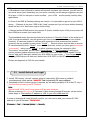
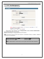
H.264MP-PTZ RTSP Streaming User’s Manual
Again, type IP address of the IP camera in Internet Explore address field; Click “Enter”
to bring up the camera Login page as illustrated below:
admin
Input User name (Default: admin)、Password (Default: admin),click “Submit” to bring up
camera video page:
Live View
System
Settings
Video
Settings
…..
Etc……..
Pan/ Tilt
control:
To control
Motion
Left,
Right, Up,
Down,
26
H.264MP-PTZ RTSP Streaming User’s Manual
Chapter 6
Software Configurations
6.1 Menu Tree
Snap
Record
Live view
Replay
Call
System/ NTP/ Storage Settings
Video/ Audio Settings
M
A
I
N
P
A
G
E
Alarm Set
Speaker
Motion
Alarm
Sensor
Log
Network Fault
Basic Set
Network Set
Zoom in
Full Screen
Advanced
Images Set
User management
Lens Control
Terminal
Storage Set
Device set
Record Set
Snap Set
Local Set
27
P/T Control
H.264MP-PTZ RTSP Streaming User’s Manual
6.2 Live View Page
In the Live view webpage, administrator can do operations :
Taking Snapshots, Recording, Playback, Talk-Back, Speaker, Alarm on/ off and Image
Parameters Settings.
【Snap】 click “Snap”, take the current image snapshot, which can be stored in your
computer hard drive in JPG format.
【Record】Manual video recording, the current video can be stored in your computer
in .MP6 format. The working status as:
【Replay】click “Replay”, it will bring up a new Playback window, user can playback the
recorded video or pictures captured.
【Call】Mic. on/ off,If user connects Microphone and Speaker with IP camera, it can
turn on the two way Audio function. The working status as:
【Speaker】Speaker on/ off,The working status as :
【Alarm】While there is an alarm, click on【Alarm】to stop the alarm manually .
【Log】Evens log
【Zoom in】Click on “Zoom in” change to red color, Select area to zoom in (live view)
28
H.264MP-PTZ RTSP Streaming User’s Manual
【Full Screen】Enlarge to full screen
【Pan control】up, down, left, right, Automatic, speed adjusting
【Image Parameters】
CCD IP Camera: brightness, contrast, chroma, saturation
adjustment as follows:
CAUTION:
Must not adjust image parameters arbitrarily or
you won’t get proper color or even “too bright” or
“to dark” image will result.
【Lens Control】It can be adjusted Zoom, Focus, Aperture,
Light, Clip, Preset, and Pan operation.
【P/T Control】Pan / Tilt operation, PAN speed adjustable
29
H.264MP-PTZ RTSP Streaming User’s Manual
Error Message
Note:
If you see above screen, which indicate your hardware is not powerful enough, please
choose PC with more advanced processor.
Minimum system requirement are:
CPU: PIII 2.0GHz or above; AMD processors are not supported
Display card : DirectX 9c compliant.
Start Run input DXDIAG
DirectDraw、Direct3D、AGP Texture Acceleration must be enabled
30
H.264MP-PTZ RTSP Streaming User’s Manual
31
H.264MP-PTZ RTSP Streaming User’s Manual
6.3 Video Playback
Click【Replay】button:
, to bring up the following webpage
User can search the recorded image files or snapshot pictures in local PC or SD card
according to date.
【Date】User can check the recorded video files or snapshot pictures according to the
selected date, click the button :
calendar appears:
Click
Click
Click
Click
“《 ”icon
“ 》”icon
“〈 ”icon
“ 〉”icon
32
to
to
to
to
previous year
next year
previous month
next month
H.264MP-PTZ RTSP Streaming User’s Manual
【PC】check the recorded video files or snapshot pictures in local PC according to the
selected date.
【SD Card】check the recorded video files or snapshot pictures in SD Card according to the
selected date.
【File List】Shows the selected recorded video files or snapshot pictures in the File List.
Check the current recorded video files or snapshot pictures in the list as follows:
Select to search for record files or snapped pictures in PC or device SD
card
The record file list searched is displayed on the left
The picture list searched is displayed on the right
The left side stands for hour, each grid means one hour
The right side stands for minute, each grid means 2 minutes
indicates the selected search period
Yellow Blue
indicates there are files and pictures searched of the selected
period
Display the files and pictures searched of the selected period
Select to search for record files or snapped pictures in PC or device SD
card
【
】Choose the recorded video or snapshot picture in play list, then click “play”
button as :
Playback control as follows:
【
】Searching the recorded video file or snapshot pictures which downloaded
from SD card in Play list, click the “
” button to download it to local PC.
【
】following window pop up after click the “
33
”:
H.264MP-PTZ RTSP Streaming User’s Manual
Click【Pause】to pause download manually,click【Start】to continue downloading
the remaining files,click【Delete】to del the file,click【Close】to close the download
information window.
6.4 System Settings
System Clock: click: “Time Sync”, the camera time will be synchronized with your computer.
【NTP Parameter】: Please input the correct NTP server address and select the correct time
34
H.264MP-PTZ RTSP Streaming User’s Manual
zone. After save it, switch to【Live View】, The NTP sever will show
the correct time got from NTP Server.
【System Information】Display name, ID number and camera type (NTSC/ PAL).
Note: Rename the IP Camera name and save it, the camera will reboot.
【Restore Default】Resume all the IP Camera parameters (Including Network parameter
except MAC address) to default factory settings.
Note: Be careful when use this function.
【Reboot】Click 【Reboot】, the IP Camera will reboot after 5 seconds.
【Upgrade】:
The sequence of the upgrade is as follows:
Step1:
Step2:
Step3:
Step4:
Application (uke)
Other (uot)
OCX (uoc)
Web Page (uwe)
Select upgrade file
【Upgrade】: Click 【Browse】button, select the correct file for upgrading.
Click 【Upgrade】to upgrade. After finished, the IP camera will reboot
automatically.
For example:The current version of IP Camera is V2.2.1.1; the new firmware version
of IP Camera from the factory is V2.2.1.3 (file: kernel_ccd_v2213.uke) , click
【Browse】button,select file:“kernel_ccd_v2213.uke”,click 【Upgrade】button,
There is information showed that the upgrade file was downloaded to Flash in IP
camera. When the upgrading finished, it shows “upgrade success”, and the IP camera
will reboot.
After reboot, login and check the new version.
Never power off Clairvoyant IP Cameras/ Video servers during upgrading.
Don’t interrupt the power and network connection during upgrading IP
camera.
Must upgrade firmware according to the correct order, first upgrade the kernel
Application, then OCX file and Web Page file.
Remember to clear up IE browser history before accessing camera after upgrading
firmware
Must download new OCX again after upgrading firmware, See page 23 for more details
35
H.264MP-PTZ RTSP Streaming User’s Manual
6.5 Video Settings
【Image】: Set image resolution, CCD Camera supports
PAL system D1 (704*576)/ HD1 (704*288)/ CIF (352*288)/ QCIF (176*144);
NTSC system D1 (704*480)/ HD1 (704*240)/ CIF (352*240)/ QCIF (176*120)
【Quality】: Options for Fine, Normal, Basic and there is advanced image setting.
【Advanced image setting】 as follows:
36
H.264MP-PTZ RTSP Streaming User’s Manual
Choose LAN or WAN defaults to get best applicable settings
Note:
Why can't get image from H.264 IP Cameras? But can access MJPEG IP camera
images with the same broadband WAN/ Internet connection?
IP Cameras with H.264 compression won't display video if I frame lost, received P/B
frames won't display without I frame, at bad network connection, packets may lost or
out of sequence, video won't start until a full I frame arrived.
Note:
I frame: full image
P frame: moving objects of I frame
P frame must join to I frame to become a full frame, if I frame lost, no video will display.
Please also check the available "upload bandwidth" , normally ADSL is very small
around 256~384kbps, please adjust the video settings to WAN defaults, adjust the bit
rate to 256kbps, adjust video resolution to CIF or QCIF to fit for lower "upload
bandwidth".
Note: the lower "upload bandwidth", the worse "network connection" the lower
resolution should choose.
Please always use smaller "I interval" for Internet accesses, the worse network
connection, the smaller "I interval" should use.
If set 2,048Kbps throughput with highest resolution (D1) and full frame rate (25fps) on
an ADSL connection with poor bandwidth, no video will display.
Please select most reliable MJPEG video compression, which sends pictures frame by
frame, will drop pictures automatically at small bandwidth, which means users will
always see pictures changing, the refresh rate is according to bandwidth available.
The parameters of video quality and frame rate are not adjustable, will automatically
adapt the available bandwidth.
This IP Camera adopts most advanced H.264 Main Profile compression with Dual
compression (h.264 & MJPEG) & Dual video Streams output, which means you can
choose most suitable compression/ resolution/ frame rate/ quality according to real
application scenario.
Note: don’t use the advanced image setting if you are not professional personnel.
37
H.264MP-PTZ RTSP Streaming User’s Manual
【Audio】 Set audio ON/OFF(Default: OFF),there are two models: Microphone and Line
input. If users don’t need audio status; please close audio input to save the DSP
resource and network resource.
【Mask Area Set】 Mask all image or Mask part image, the whole image divided into 22 * 18
blocks. Select the blocks to mask, or cancel the mask setting.
6.6 Motion Alarm Setting
Setting motion alarm parameters: included the schedule time, on/ off the alarm, sensitivity,
trigger alarm output, alarm delay, alarm recording on PC storage or capture snapshot to SD
card when alarming. ( The snapshots stored on SD card can be downloaded to PC on
【replay】page)
【Schedule】Set the time of motion alarm detection.
【Alarm output】Alarming, trigger alarm signal output.
【Alarm delay】Alarming, delay the alarm (the period of time after alarm that continuous
alarms will be ignored) automatically ,set the time from 0~86400 seconds.
【Alarm record in PC】Automatically recording video and stored it on PC storage when
38
H.264MP-PTZ RTSP Streaming User’s Manual
alarming if no SD card in camera.
【Alarm snapshot in SD Card】Automatically capturing image and stored it in SD when
alarming. If there are continuous alarms, the interval
time of capturing is the delay time. For example, the
alarm delay is 10 seconds; it will capture an image
stored in SD card every 10 seconds. The image in SD
card can be downloaded to PC when replay. And when
the SD is full, the old file will be over written
automatically.
【Area set】: Hold the left button of mouse and drag the motion detect area.
【All】Set whole image as motion detect area
【Clr】Clear all motion detect area.
After setting, click the 【save】button.
6.7 Sensor Alarm Settings
Setting sensor alarm parameters: include the schedule time, on/ off the sensor alarm, sensor
state, alarm output, alarm delay, alarm record on PC storage or capture snapshot on SD card
when alarming.
【Schedule】Set the time of sensor alarm detection.
【Alarm output】Alarming, trigger alarm signal output.
【Alarm delay】 Alarming, delay the alarm (the period of time after alarm that continuous
alarms will be ignored) automatically ,set the time from 0~86400 seconds.
【Alarm record on PC】Automatically recording video and stored it on PC storage when
alarming if no SD card in camera.
【Alarm capture on SD Card】Automatically capture snapshots, stored on SD when
alarming. If there are continuous alarms, the interval of
snapshots is the delay time. For example, the alarm delay
is 10 seconds; it will capture an image store on SD card
39
H.264MP-PTZ RTSP Streaming User’s Manual
every 10 seconds. The snapshots on SD card can be
downloaded to PC when 【replay】. And when the SD is full,
the old file will be over-written automatically.
After setting, click the 【save】button.
40
H.264MP-PTZ RTSP Streaming User’s Manual
6.8 Network Setting
Setting IP Camera address, Subnet mask, Gateway, MAC, Data port、HTTP port、DNS
address. The device will restart after setting and save. If IP camera is connected to Wi-Fi
network, please don’t use the same subnet IP addresses for both wired & Wi-Fi.
Please make sure the IP camera IP is set to the same “subnet” of your LAN IP, please
consult MIS or network engineer if don’t understand what is “subnet”
If connect IP Camera directly to your PC, please make sure your PC IP is the same “subnet”
of your IP Camera, make sure to set your PC IP to manual settings.
Before you can connect your IP camera from Internet, please must read below check points:
It's impossible to access LAN IP from Internet, IP started with 192.168.xxx.xxx is LAN IP,
LAN IP is illegal IP, Only legal public IP can be accessed through Internet.
No one can access your LAN IP through Internet or you will be in big security threat, Hackers
can access your bank account and secrets stored in your LAN PC
1. Broadband router is firewall in nature will block all accesses from Internet, you will need to
set virtual server (port forwarding) on your router, normally we will always suggest to use
port > 1024 to avoid conflicts, port <1024 are frequently used by other applications.
41
H.264MP-PTZ RTSP Streaming User’s Manual
2. Check if the DNS & Gateway settings are correct, it is impossible to get out of your LAN if
wrong.
(Gateway is the door, DNS is like "map", people won't go out home without
knowing where the door is or don't have map to find the way)
3. Always test the DDNS service from another IP (that is outside of your LAN); some router
will block WAN port access from LAN.
Please consult qualified network engineers for more details.
CAUTION:
If “Enable WiFi” check box is checked, will enable camera wireless
interface, the camera won’t respond to the broadcast search request
cross subnets!!
Please must write down the wired LAN IP address before you enable Wi-Fi!!
SearchNVS.exe won't be able to find camera if your PC is not on the same subnet.
You won’t be able to find the camera by IP camera search tool (NVS Search), if you
have not correctly set the wireless network parameters or Wi-Fi AP has been switched
off, even you have connected your camera to LAN by Ethernet cable.
WiFi Parameters
【IP address】The IP address used to connect to your wireless network (wireless router/ AP),
for example: 192.168.1.160
【Gateway】Wireless network gateway (wireless router/AP), for example: 192.168.1.1
【SSID】 The unique SSID of your wireless network. This SSID must be same as the SSID
of your wireless network (wireless router/AP). Save the parameters after setting.
Disconnect the Ethernet cable, visit IP camera through wireless IP address, for
example 192.168.1.160.
【Type of encryption】WEP, WPA, WPA2
【Mode】802.11b or 802.11g (choose 802.11g for better performance)
Note: The IP of wireless network can’t be same as the IP of wired network.
DDNS Setting
Enable Dynamic Domain Name Service will bind your camera with a fixed Domain Name
(URL); user will access the camera by the URL, no matter what the dynamic WAN IP address
may vary all the time.
【DDNS RegName】User account registered on DDNS server
【DDNS Password】User Password of DDNS server.
【DDNS Domain】The unique URL set for internet access.
【DDNS Server URL】Dynamic Domain Name Service provider URL.
【DDNS Port】Default :30000.
【Data Port Map No】Default :5000, is the TCP/IP port open on your Gateway/ Firewall which
will forward to your camera.
【HTTP Port Map No】Default :80, is the TCP/IP port open on your Gateway/ Firewall which
will forward http access to your camera.
Note: If other than port 80 used, you will need to add http port number every time you access
your camera by IE browser. (ex: http://Camera_IP_Address(URL):port )
42
H.264MP-PTZ RTSP Streaming User’s Manual
PPPOE:
Dial-up setting, enable PPPOE if connect your camera to ADSL modem directly.
Get PPPOE Username, Password from your ISP, click 【Save】button
Note: Please kindly notice the below facts of wireless video.
1. Most wireless cameras are 2.4GHz Wi-Fi, some are 11b, some are 11g
2. Most home routers are with 2.4GHz Wi-Fi, that support 11b+g by default.
3. Most SOHO routers are with relative weaker power to be complied with European ETSI
regulations on wireless devices (Antenna + AP: total power < 20dBm)
4. The true throughput of 2.4Ghz Wi-Fi is 20Mbps maximum (not 54 or 108Mbps), will be
lesser (down to 1Mbps or smaller) for longer wireless link distance or weaker signal strength
(due to interference, wall, door, windows)
5. The IP camera video will be unstable (not fluent, bad quality, unclear with big square
blocks), if packets lost during wireless transmission.
6. The Wi-Fi transmitting protocols will identify packets lost, will try to resend over and over
again until transmit successful. Resend packets will jam the effective bandwidth under bad
wireless link (interference, weaker signals)
7. The resend packets (previous lost packets) received will be discarded as useless garbage,
because it is out of sequence, out of sequence video frames are useless because of the real
time nature of video.
Conclude the above facts, that's the reason why SOHO Wi-Fi AP will support "no more than
(4) wireless cameras", but it is not necessary to be true, if we can conquer below difficulties:
1. For FCC regulations, it is not strictly limited the wireless power as European Countries, we
can choose professional AP with higher power, plus higher gain directional antennas.
2. Choose only 802.11g wireless cameras, set the wireless AP to 802.11g mode only, to get
best throughput. Note: 802.11b maximum throughput is only 4Mbps.
3. Choose more professional IP cameras with H.264 video compression that require lesser
bandwidth per camera (30fps @D1, NTSC; 512kbps ~2Mbps maximum).
4. Avoid obstacles in between AP & IP Camera.
Choose different wireless channels for
adjacent AP.
5. Choose 802.11a (5.8GHz) for longer range wireless link, or under serious interference to
ensure good wireless link quality.
43
H.264MP-PTZ RTSP Streaming User’s Manual
6.9 Advanced Settings
Mail Setting:
When there is a motion alarm, the camera will send the alarm mail to the designated email
box automatically
【SMTP Server】Your Email server address, for example: Hinet mail, the SMTP server is
msa.hinet.net
【Mail From】sender email address.
【Mail To】 receiver email address.
【SMTP User Name】Your User account on SMTP server, please check your outlook email
settings.
【SMTP Password】Your User Password on SMTP server, please check your outlook email
settings.
【Mail Title】Title of the alarm mail.
【SMTP Port: 】port of SMTP port, different mail server has different port. For example, the
server
Note:
Gmail mail server:
SMTP server: smtp.gmail.com
SMTP user name: [email protected]
SMTP port: 465
SSL: enabled
Yahoo mail server:
44
H.264MP-PTZ RTSP Streaming User’s Manual
SMTP server: smtp.mail.yahoo.com
SMTP user name: [email protected]
SMTP port: 465
SSL: enabled
UPNP Setting: Port mapping automatically: The Gateway/ Firewall server with UPNP
function will map port for camera automatically.
【UPNP Network Card】The camera interface connect to UPNP Gateway/ Firewall.
【UPNP mode】There are Designate and Auto modes:
Designate mode: Camera will designate the data port and web port to
UPNP Gateway/ Firewall.
Auto mode: Camera will get the data port and web port from UPNP
Gateway/ Firewall.
【UPNP server】Gateway/ Firewall IP address.
【Data mapping port】data mapping port of user-specified device on the router(works only
under specified mode).
【Web mapping port】web mapping port of user-specified device on the router(works only
under specified mode).
【Data mapping port status】When UPNP function runs successfully, the status bar will echo
the data port mapped to the router by the device.
【Web mapping port status】When UPNP function runs successfully, the status bar will echo
the web port mapped to the router by the device.
click【save】After setting.
Note:
Camera is fully functional UPnP client, will communicate with UPnP Server through standard
UPnP protocols, The Gateway/ Firewall must supports UPnP Server functions.
FTP Setting: Upload snapshot at alarm (motion & sensor), or by scheduled period of time
(example: every 1 minute).
【FTP URL】Your FTP server IP address (or our LAN DISK), for example:192.168.66.10
【FTP port】default is 21.
【FTP Username】 FTP account name.
【FTP Password】Your account password on FTP server.
【FTP catalog】folder to store snapshots.
Note: FTP URL must be IP address, don’t support domain name.
RTSP Setting: Enable RTSP streaming, will be compatible with vlc player, Coreplayer &
Real player on 3G phones
【RTSP port】default port is 554.
click【save】After setting.
45
H.264MP-PTZ RTSP Streaming User’s Manual
WARNING: If RTSP enabled, authentication is not required to playback live
video & audio by vlc media player.
Please be aware of privacy risk.
To play on vlc, Coreplayer (iPhone, Smart phones), Realplayer (Nokia Symbian)
Syntax
rtsp://Camera_url_or_WAN_IP:rtsp-port
Example:
rtsp://www.ipcamera.com.tw:554
【Public IP mail notification】
Mail notification on/off: check this switch to enable public IP mail notification function.
Interval: select the interval of public IP mail notifications.
After enable this function, when the device starts or detects public IP change, it will send
notification mail to the mail address set in “mail settings”.
46
H.264MP-PTZ RTSP Streaming User’s Manual
6.10 User Management
There are two user accounts. One is Administrator another is Guest. Administrator
can change parameters of IP Camera.
Guest is not allowed to change parameter of IP Camera.
Note: Username/ Password are case sensitive, consisted of letters, numbers, underline
or dot up to 16 characters.
Default Administrator Name: admin
Default Guest Name: guest
password: admin
password: guest
Note: It’s case sensitive, must use the correct upper case/ lower case characters
47
H.264MP-PTZ RTSP Streaming User’s Manual
6.11 RS-485 Settings
[PTZ address]: 1~256.
Default C1281IR PTZ address: 1
If need to change PTZ address, must change dip switches in camera to match with new
address.
See Appendix for dip switches settings.
.
Note:
Must set parameters and protocol correctly, PTZ won’t be controllable if change parameters.
Not necessary to change above settings unless you want to use keyboard/joystick to control
multiple speed dome cameras.
Suggest to match camera PTZ address with windows number set on CMS.
Baudrate
: 2400bps
Data bits
:8
Stop bits
:1
Check type : none
Flow ctrl
: none
Protocol : PELCO_D(STD_Speed).COD
click【save】after setting.
48
H.264MP-PTZ RTSP Streaming User’s Manual
6.12 Storage Settings
[Storage Device information]: view information of SD card here, including total capacity, free
capacity, and formatting status. Users can also click [Formatting] button to format SD card,
during the formatting process, please click [Refresh] button to the display formatting completion
percentage.
49
H.264MP-PTZ RTSP Streaming User’s Manual
[Device Recording Parameters]
Stream selection: set record stream for SD card, preferred stream and alternate stream are
selectable.
Record files packing interval: set packing intervals for each segment of record file when SD
card is recording.1 means files will be packed every 1 minute.
[Other Parameters]
IP Camera User’s Manual
20/31
Automatically delete old files when storage device gets full: when the storage capacity of SD
card is used up, the device will delete old files automatically. The way to delete old files: first
delete the files of the earliest date, if the space is still not enough, then delete the files of the
earliest date but one, then go on like this if necessary. If the record files are taken on the
current date, then first delete the files of the earliest hour. But files of the current hour cannot be
deleted, if the SD card gets full in one hour, the device will stop recording and snapping images.
After the one-hour session ends, system will delete the files of the hour and continue to record
and snap pictures.
Scan the disk when device starts: check storage device or not when IP camera starts.
Note:
1 Do not cut off the power of the device during formatting process.
2 ext2 file is used to format system by default.
After setting all the parameters, click [save] to make the parameters valid.
CAUTION:
Never hot-swap SD card that may damage the SD card, valuable recording
stored in SD card will be lost!!
50
H.264MP-PTZ RTSP Streaming User’s Manual
Record schedule
[Device Record Schedule]: set the period of scheduled recording, two periods allowed.
[Record file storage mode]: set to save scheduled recorded files to FTP server via FTP
uploading,
FTP server can be set up in [FTP settings].
Note: record files are saved via FTP uploading. SD card is needed for cache memory support,
otherwise record files will be overwritten by new files due to insufficient cache memory space.
After setting all the parameters, click [save] to make the parameters valid.
51
H.264MP-PTZ RTSP Streaming User’s Manual
Snap schedule
[Picture snapping parameters of the device]: set the interval of IP camera picture snapping,
minimum interval is 1 second.
[Device Snap Schedule]: set the period of scheduled snapping, two periods allowed.
[Snapped files saving mode]: IP camera snapped pictures can be saved via E-mail sending or
FTP uploading. E-Mail server can be set up in [Mail Settings], FTP server can be set up in
[FTP Settings].
After setting all the parameters, click [save] to make the parameters valid.
Note:
Record files are saved via FTP uploading. SD card is needed for cache memory support,
otherwise record files will be overwritten by new files due to insufficient cache memory space.
52
H.264MP-PTZ RTSP Streaming User’s Manual
6.13
Local Settings
[PC live preview parameters setup]
Stream selection: set video stream for PC live preview, preferred stream and alternate stream
are selectable. The parameters of preferred and alternate stream can be set up in [Video
Settings].
Preview mode: users can choose real-time priority or fluency priority mode according to their
needs.
[Anti-crack]: select this option to make image quality better, but CPU usage rate will be higher
at the same time.
[PC record storage settings]
Record files packing time: set packing time of record files for local PC when it is recording.
Record/snapped files storage directory: set the storage directory for local records and snapped
files, the default path is C:\XDNVS.
53
H.264MP-PTZ RTSP Streaming User’s Manual
Appendix 1
TCP
UDP
Multiple
port
Appendix 2
Network Port for IP Camera
80 (Web port)
5000 (Communication port, Audio/ Video
data transmitting Port, Talk data
transmitting Port)
5000
Audio/Video data transmitting Port
Multiple original port + Channel Number
Network Factory Defaults
Wired network defaults:
IP Address:
192.168.55.160
Subnet Mask: 255.255.255.0
Gateway:
192.168.55.1
Data port: 5000
Web port: 80
DHCP:
OFF
Wireless network defaults:
IP Address: 192.168.1.160
Gateway:
192.168.1.1
Subnet Mask: 255.255.255.0
Frequency /Mode: Auto
Note: The wireless network can’t be the same as the wired network.
Must be different subnet
Appendix 3
DDNS introduction
DDNS function of IP camera
DDNS (Dynamic Domain Name Service) refers to the real-time analysis of a fixed domain
name and the dynamic public IP address of the IP camera. With this function, all Internet
users can visit the IP camera via a fixed domain name.
54
H.264MP-PTZ RTSP Streaming User’s Manual
The DDNS process of IP camera is as follow:
The DDNS process flow diagram of IP camera
Apply for DDNS domain name service
Step 1: Sign up
Users need to sign up to manage and inquire about domain name status when using this
dynamic domain name management system for the first time. Visit DDNS server
(http://www.mvddns.net) to sign up. See the picture below:
55
H.264MP-PTZ RTSP Streaming User’s Manual
Step 2: User login
Enter registered user name and password, click “login” to enter into domain name
management interface as follow:
Step 3: Domain name registration
A domain name must be registered first, and then put into use. Click “Domain name
management”, a page appears as follow:
56
H.264MP-PTZ RTSP Streaming User’s Manual
Register and submit the domain name to be used. For example: “test.mvddns.net”.
Appendix 4
FAQ
1、 Forget Password
Solution: There is a [RESET] button on the back panel of the IP camera, press it to restore all
default parameters (Factory Settings), user name and password are both “admin”.
Note: Please don’t press RESET if you are not a professional operator. After reset, all
parameters will restore factory settings (except for the physical network address).
2、 IP camera audio/video function fails after abnormalities or abnormal power cut occur
during upgrade, core edition is V4.0.0.0 (Backup file)
Solution: Connect the power cord and network cable of IP camera, press on RESET button and
release it after 10 seconds, system will run the back-up program automatically. After enter into
the back-up program, upgrade system.
After upgrade completes, the IP camera will work
normally. The back-up program offers only upgrade and parameter setup functions, audio and
video functions are not available.
3、No video image displayed in IE browser
Possible reason: ActiveX not installed
Solution: ActiveX must be installed when visiting IP camera for the first time via Internet
Explorer.
How to install: Visit IP camera, click [Download Address], file download dialog will pop up,
select [Run] or [Save] to download. After download finishes, installation interface will pop up,
click “install”, the installation of ActiveX will start automatically, “Register OCX success” dialog
box will pop up to remind the completion of installation process.
57
H.264MP-PTZ RTSP Streaming User’s Manual
4、 Fail to visit IP camera via IE after upgrade
Solution: Delete the caching of Browser.
Steps: Open IE—click “Tools”—select “Internet Options”—click “delete files” button in “Internet
temporary files”, select “delete all offline contents”, then click “OK” and re-log in IP camera.
5、 The images do not flow
Possible reason 1: The frame rate of IP camera is too low.
Solution: Increase the video frame rate
Possible reason 2: Too many users are viewing the images.
Solution: Block some clients or reduce the video frame rate.
Possible reason 3: The bandwidth is low.
Solution: Reduce video frame rate or video compression bit rate.
6、 Fail to visit IP camera via IE browser
Possible Reason 1: Network is disconnected.
Solution: Connect your PC to network, checking whether it works properly or not. Check
whether there is cable failure or network failure caused by PC virus, until PCs can be
connected with the command of Ping.
Possible reason 2: IP Address has been occupied by other devices
Solution: Stop the connection between IP camera and Network, hook up IP camera to PC
separately, reset IP address according to the proper operations recommended.
Possible reason 3: IP addresses are in different subnets.
Solution: Check IP address, subnet masking address of the DVS and the settings of Gateway.
Possible reason 4: Physical address of network conflict with IP camera
Solution: modify the physical address of IP camera.
Possible Reason 5: Web port has been modified
Solution: Contact Network Administrator to obtain related information.
Possible Reason 6: Unknown
Solution: Press RESET to restore default settings then connect it again, the default IP address
is 192.168.55.160, subnet mask is 255.255.255.0
7、 The color of images is abnormal (green or other colors)
Solution: Sometimes IP camera images cannot display properly for the difference between
Graphics Cards, the images appears to be green or other colors, then you should run
Config.exe (or run C:\windows\system32\Config.exe) to set the following parameters of display
buffer: auto-detection, used display card memory or system memory, then reopen IE and
connect IP camera.
8、 There is no sound while monitoring
Possible Reason: No audio input connection
Solution: Check audio connection of the host
Possible Reason 2: the audio option of IP camera is off
Solution: Check audio parameter settings to see if you have opened the audio.
9、 Search NVS software cannot find device
58
H.264MP-PTZ RTSP Streaming User’s Manual
Possible reason: Search NVS software adopts multicast protocol to perform searching. But the
firewall forbids multicast data packet.
Solution: disable the firewall.
10、 What is my public IP address
Use http://checkip.dyndns.com/ will reply
“Current IP Address: 116.77.192.104”
11、Routers and Port Forwarding
For a collection of step-by-step guides for many common routers, please visit
PortForward.com.
http://portforward.com/help/portcheck.htm
One of the most common devices in any given network — after computers, of course — is the
router. Sitting between the modem and the other devices in the network, the router's job is to
route (direct) traffic to and from the Internet and devices in the local area network (LAN),
sharing a single Internet connection between multiple devices.
A router is more than just a glorified cable splitter, however; in addition to intelligently juggling
packets and priority between devices to ensure smooth data transfer, most routers include a
variety of features including Quality of Service settings, virtual private network options, web
content filtering, time-delimited access restrictions, and more.
At factory default, most routers are preconfigured with a variety of security settings, including a
firewall set to reject new incoming connections to the network. This security measure is simple,
effective, and rarely obtrusive; surfing the Internet, watching streaming video and chatting with
friends and family is uninterrupted, since these connections are established first by an outgoing
connection from the LAN.
Since the router's firewall prevents Internet visitors from reaching any devices in the LAN, the
user must open a tunnel in the router's firewall to allow specific external connections to reach a
specific destination device while keeping the rest of the network safe.
Port Forwarding
All TCP and UDP traffic on the Internet uses ports to identify the protocol being used, such as
port 80 for HTTP (web) and port 25 for SMTP (email). To solve the firewall problem and let
visitors into the network, the user instructs the router to allow traffic to pass through on a given
port. This is known as port forwarding, as the router forwards (directs) all Internet requests on
a specific port to the local machine. With port forwarding, external visitors are able to connect to
the server while other internal devices remain protected.
There are three different kinds of port forwarding:
59
H.264MP-PTZ RTSP Streaming User’s Manual
•
•
•
Port Forwarding: Standard port forwarding is an "always on" tunnel through your
router's firewall. Any visitor may connect to your network on the given port at any time.
This is the correct choice for "always on" services such as web servers and mail servers.
Port Triggering: This is a special kind of "temporary" port forwarding that requires an
initial outgoing connection. Once the connection is established, the router begins
forwarding all new incoming connections to the local machine; when the local machine
closes the connection, the forwarding rule is turned off. This rule is most commonly used
in gaming, video conferencing and other applications that receive incoming connections
on a need-only basis.
DMZ (DeMilitarized Zone): This feature effectively places the destination device outside
of the router's protective firewall by forwarding all incoming connections on all ports to
the single local machine. The DMZ is mostly used for troubleshooting purposes and
advanced network configurations; as such, it is not recommended to use the DMZ for
general hosting purposes.
In most routers, a port forwarding rule take the following information:
•
•
•
•
Application Name: The label for the forwarding rule.
Start and End Port: The application's port(s), e.g. 80 for HTTP. Many routers will allow
you to forward an array of ports with a single rule.
Protocol: The protocol (TCP, UDP or Both) for the forwarding rule. The protocol
depends on the type of service you are providing (e.g. webservers use TCP).
IP Address: The internal IP address of the destination device in the LAN, usually
beginning with 192.168.x. If your router dynamically assigns internal IPs with DHCP, you
will need to configure the server device to use an internal static IP address.
The best source for more detailed information about routers and port forwarding, as well as
step-by-step pictorial walkthroughs for most common routers, is PortForward.com. If you are
setting up a new service and configuring your router for the first time, it is highly recommended
to read their guides and walkthroughs to determine the necessary changes you will need to
make to correctly forward ports in your router.
60
H.264MP-PTZ RTSP Streaming User’s Manual
Appendix 5
Speed Dome Setup
CAUTION: Settings in this section are restricted to professional technical
personnel, wrong settings may cause mal-functional, lost control, will result
un-necessary RMA.
The default camera settings of C1281IR speed dome camera:
IRIS
BLC
Digital Zoom
IR Cut
IR LED
Proportion pan
Mortor speed
Power up action
Auto Park
Auto Scan
180º TILT/ auto flip over
Baud rate
Address
Protocol
auto
off
on
auto
Full on
on
fast
On (go to preset 1)
off
off
on
2400 bps,n,8,1
1
PELCO_D(STD_Speed)
61
H.264MP-PTZ RTSP Streaming User’s Manual
Set preset
Recall preset
62
H.264MP-PTZ RTSP Streaming User’s Manual
Power up or after call preset 94 to restart
63
H.264MP-PTZ RTSP Streaming User’s Manual
Recall preset 95 to bring up OSD menu
CAUTION: Settings in this section are restricted to professional technical personnel,
wrong settings may cause mal-functional, lost control, will result un-necessary
RMA.
To call up C1281IR dome camera setup main menu by recalling preset 95, as illustrated
below:
To move cursor up and down by
,
Focus Near act as “Enter”
Focus Far act as “Esc”
64
H.264MP-PTZ RTSP Streaming User’s Manual
65
H.264MP-PTZ RTSP Streaming User’s Manual
To display the dome camera status on screen, choose items to turn on.
66
H.264MP-PTZ RTSP Streaming User’s Manual
67
H.264MP-PTZ RTSP Streaming User’s Manual
68
H.264MP-PTZ RTSP Streaming User’s Manual
There are 127 preset points, 8 swings, 4 patterns (200 commands), 8 Privacy zones
(Sony cameras) can be set.
8 groups of presets+swings+patterns to form more
complicate patrol route. (20 actions per group)
69
H.264MP-PTZ RTSP Streaming User’s Manual
70
H.264MP-PTZ RTSP Streaming User’s Manual
Manual Speed:
SLOW : 0° ~45°/ sec
NOR : 0° ~90°/ sec
FAST : 0° ~180°/ sec
71
H.264MP-PTZ RTSP Streaming User’s Manual
Appendix 6
Cross Ethernet Cable Making Tip
I. LAN Plug
Pin: 1 ~ 8
II. LAN Cable
PART-A
PART-B
III. Connection Method
a. Connect LAN Cable Part-A and LAN plug by order as one to one .
b. Connect to LAN cable Part-B & Part-A, Replace order No.1 & 3, No.2 & 6.
c. Connect LAN cable Part-B No. 3 to LAN plug No. 1 and connect the next by order.
72
H.264MP-PTZ RTSP Streaming User’s Manual
========================== The End =========================
73