1
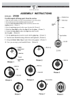
RX4 Transponder Detector Installation Manual
Table of Contents
1.0 Introduction
2.0 Terminology
3.0 Plan Your Feedback System
3.1 Basic Transponding
3.2 Advanced Transponding
4.0 BDL16 Installation
5.0 The RX4
6.0 RX4 Installation
6.1 RX1 Sensitivity
6.2 Option Switches for BDL16 that affect transponding
7.0 Setting Up Locos & Other Rolling Stock for Transponding
8.0 RX4/BDL16 Troubleshooting: Checklist
8.1 Packet Reception-BDL16
8.2 Mode Indication-BDL16
8.3 Occupancy Debug-BDL16
8.4 LocoNet Debug-BDL16
8.5 Transponder Debug-RX4/Decoder or other transponder
8.6 Using a Test Transponder for de-bugging
9.0 Warranty and Repair Information
10.0 FCC Information
2
3
4
4
5
5
5
6
7
10
11
12
12
12
12
12
12
13
14
14
Digitrax, LocoNet, Genesis II, Empire Builder II, Chief II, Super Chief, and
others included in this manual are trademarks of various manufacturers including Digitrax and others. There are many different manufacturers who build
products that work with Digitrax, those used in this manual are for example
only. U.S. & International Patents Pending for BDL16, RX4, transponding and
other Digitrax products & technologies
Copyright Digitrax, Inc. All rights reserved. Printed in USA.
1
REV 03/01
1.0 Introduction
2.0 Terminology
The RX4 is 4 Zone Transponder Detector for use with the Digitrax BDL16
Occupancy Detector and Digitrax transponders. The addition of an RX4
allows the BDL16 to track and inform LocoNet of the layout location and identification of rolling stock equipped with transponders. Digitrax transponders
are available as stand alone units which can be used to retrofit existing DCC
decoder installations or can be installed separately in rolling stock that is not
decoder equipped. Many Digitrax premium decoders come transponder
equipped so that no retrofit is necessary.
The following list of terms will be helpful as you learn more about Digitrax
detection and transponding.
Digitrax transponding is an area detection technology that works something
like this:
1. Transponders (either included in a decoder or a separate transponder
like a TD1 or TL1) installed in locos and rolling stock create small
current pulses.
2. Transponder detectors (BDL16s with RX4s) installed on the layout
use advanced digital signal processing, DSP, to determine which
transponder is located in which transponding zone.
3. When a transponder equipped piece of rolling stock is located in a
zone equipped with a transponder detector, information about the
unit’s address and zone location is reported to LocoNet and can be
displayed on a detection panel or computer screen, displayed in
DT400 throttles, used for layout automation, etc.
Power district is the power wiring, components and equipment attached to that
wiring, driven by a single properly isolated booster. Power districts are double
gapped on both ends. BDL16 is used to set up detection sections within one or
more power districts.
Each transponder is programmed with a unique address that lets the transponder detector keep track of many different transponders at the same time, even
when they are located in the same transponding zone.
Transponding can be used with most DCC compatible boosters and decoder
installations. To make this work, just set up LocoNet wiring and hook up the
BDL16’s and RX4’s. Transponding can also be adapted for use on almost any
model railroad control method!
Transponding detection technology works with current pulses that are so low
that there is no danger of interference with decoders or track control signals.
Transponding can be combined with other means of occupancy detection to set
up a customized feedback system for your layout at a very reasonable cost.
Direct home wiring is a layout wiring method where each power district and
its booster is electrically isolated. The track within each power district uses a
"common return" wiring method for occupancy detection and/or power management. Direct home wiring is the wiring method recommended by Digitrax
for safety reasons & also because it makes detection work more prototypically.
Power sub-district is the wiring, components and equipment that are controlled from both power bus wires by their own power management device, for
example a reversing section controlled by an automated reversing device like
the PM4. Power sub-districts are double gapped on both ends.
Detection common is the common return used within a properly electrically
isolated power district for implementing occupancy detection.
Zone common is the common return used to implement zone transponding.
Zone common connections to the booster should be as short as possible and
relatively heavy gauge since they are common to all four detection sections in
each zone.
Security element is the plant, including track, associated with any reporting,
interlocking and/or signaling for that track section.
Whole layout common rail is a method of wiring layouts where power districts and their boosters are connected electrically by a common rail or common power bus return wire. This method is traditionally used for conventionally controlled layouts. The track feeds for one rail are connected together to
one output of the power pack. The other rail is gapped and the track feeds are
connected to the power pack through block control switches. Whole layout
common rail wiring has a disadvantage when it comes to detection systems
because detectors are not able to independently monitor whether zone power is
on or off. There is no way to tell whether occupancy detection is actually
working in any given detection section.
Detection Section is a section of track gapped on one or both rails and con-
2
3
nected to an occupancy detector so that the detector can sense the presence of a
loco (or other specially equipped cars) in that section of track.
Occupancy detector is a device that senses the presence of a locomotive (or
other specially equipped cars) in a section of track that is set up for occupancy
detection. Occupancy detectors also provide feedback to indicate occupancy.
This feedback may be in the form of a lamp on a control panel or it may be a
feedback message sent to the system that can be used by other layout devices.
Also called a block occupancy detector on conventional layouts. Detectors are
not covered by the DCC Standards or Recommended Practices.
Transponder is an electronic device with a transponder address that is
installed in rolling stock. Transponders provide information to transponder
detectors installed on the layout. This lets the system determine in which
transponder zone the transponder is currently located. Transponders are included in many Digitrax premium decoders. TD1 (transponder) & TL1 (transponder with light output) are available as separate units that can be added to locos
with existing decoders or to other rolling stock without decoders if you want to
use them for transponding only and don't need motor control.
transponding example presented here will show you how to set up 4 transponding zones each with 4 detection sections using one BDL16 & one RX4. For
most layouts, this set up will be just what is needed. If your plan calls for
other capabilities, instructions for more advanced options are also available.
Before you begin planning and wiring your layout for transponding, you may
want to set up a test transponder as described in Section 8.6 of this manual.
This will help you become familiar with the concepts involved in setting up
transponding and will be a useful de-bug tool as you proceed with the actual
installation on your layout.
3.2 Advanced Transponding
The combination of BDL16 & RX4 and the addition of other LocoNet components like the PM4 offer many additional possibilities for detection &
transponding that are not be presented in this manual. Please visit our web site
www.digitrax.com Application Notes and Technical Information page to print
out additional ideas and examples for advanced transponding & detection. If
you are not able to find these documents on the web site, our tech support staff
will be happy to mail or fax copies to you upon request.
4.0 BDL16 Installation
Transponder detector is an electronic device installed in a detection section
on the layout that receives the information broadcast from a transponder. The
transponder detector sends feedback to the system that lets it determine the
detection section location of any given transponder at any time. RX4
Transponder detectors are hosted by the BDL16 and upgrade 4 detection zones
of the BDL16 to be transponder detection zones. In this case, each transponding zone encompasses 4 detection zones.
Transponder zone is an area of track that may be single gapped on one rail or
double gapped on both ends and equipped with a transponder detector. Up to
four detection sections can be included in a transponder zone.
3.0 Plan Your Feedback System
Before you begin installing BDL16’s & RX4’s you should carefully analyze
your layout and what you want to achieve with your feedback system. The
best choice is usually a combination of detection sections and transponding
zones. To use transponding effectively, you do not need to set up transponding
on every section of track. By using transponding and other types of detection
technologies in tandem, you will be able to get excellent performance and
results at the lowest possible cost.
3.1 Basic Transponding
This manual presents basic transponding & detection wiring. The zone
4
The BDL16 is used to host your RX4. It provides the LocoNet connection
and wiring connections you will need to set up the layout for feedback. Before
installing your RX4, you will need to have a BDL16 installed. The manual
that came with your BDL16 will guide you through how to do this and how to
troubleshoot problems with the BDL16.
5.0 The RX4
Each RX4 is made up of 4 RX1 sensors, a ribbon cable and a connector that
let’s you plug the unit into a BDL16. The RX1’s are very sensitive to current.
The detection level is sensitive enough that reliable detection & transponding
can be achieved with transponding current levels of only 1-2% of the zone current. In most cases, a level of 20-30 milliamps is enough for dependable operation. For example, on a N-scale board decoder, the 470ohm dropping resistor
that comes installed on the board is enough current for a zone of 2-3 amps.
See Section 7.0 for more information about enabling your transponder
equipped decoders for transponding.
Because of the high sensitivity level of the RX1’s their placement relative to
the zone common wires is important to avoid interference among the RX1’s
installed on the layout. Follow the spacing instructions carefully to be sure you
have the best operation possible.
5
In your installation, you will pass the zone common wire from the booster to
the track through the RX1 sensor. The direction in which you do this is important. To make this easy, each RX1 has text on one side and is blank on the
other. The instructions that follow will indicate which direction you should use
to achieve the desired results.
Digitrax RX4 Diagram
Text Side
R
RX1
Patents
Pending
Brown/Red
Ribbon
RX4 Ribbon Cable
Orange/Yellow
Ribbon
Black/White Not Used
R
Non-Text
Side
R
Blue/Green
Ribbon
RX1
Patents
Pending
Connector for
plugging in to
BDL16
AUX2 header
Gray/Violet
Ribbon
Each RX4 is made up of 4 RX1's
Wire Color
Brown & Red
Orange & Yellow
Green & Blue
Violet & Gray
1. Plug the connector on the end of the ribbon cable connecting the four
RX1 sensors that make up the RX4 into the AUX2 socket on the
BDL16. Do not use the AUX1 socket for this connection. The
black stripe on the cable should be plugged in towards the board
edge connector side of the BDL16 board.
2. For each transponding zone you want to set up,
a. Pass the zone common wire from the DCC booster’s Rail A (or
B) terminal through the center hole of an RX1 from the "nontext" side and exit from the "text" side of the RX1 sensor
b. Loosely twist the zone common wire together as you route it
away from the RX1. Be sure you route the zone common wires
at least 2” away from all other RX1’s.
c. Connect the zone common wire to the appropriate pin on the
BDL16's board edge connector.
6.1 RX1 Sensitivity
RX1
Patents
Pending
Section 8.6 before beginning the first RX4 installation.
Detection Zone
Zone A
Zone B
Zone C
Zone D
The black and white wires in the RX4 cable are not used or connected.
RX1 sensors are extremely sensitive to current, for best results:
1. The zone common wires that pass through each RX1 should be kept
at least 2 inches from any other RX1 sensors.
2. Form these high current leads in a bundle away from the mounted
RX1's.
3. The ribbon cables on the RX4 can pass close to the RX1's with no
effect.
4. Transponding related option switches on the BDL16 should be set up.
The factory setting for LocoNet Railsync polarity for a cable connecting the BDL16 to a DCS100 or DB150 is such that the default
board polarity of the BDL16 is correct with the factory defaults.
Option Switch 3 can be used to swap the board Railsync polarity
5. The presence of any active transponder in a transponding zone will
cause that related zone power indicator LED to blink. When there is
no transponder in a transponding zone, the LED will be on steady.
It is useful to make up four of the 5 LED test cables as detailed in
the BDL16 Manual. These will let you see the occupancy status of
each of the 16 detection sections and also show zone power and
transponding status, for simplified debug. Transponder capable software, a LocoNet message monitor and other transponder capable
LocoNet devices can display the unique transponder messages, confirm those messages and use those messages to automate tasks on
the layout.
6.0 RX4 Installation
First time RX4 users may want to set up the test transponder described in
6
7
RX1
Text
Side
Brown/Red Ribbon
Loosely twist zone
common wires as
illustrated here.
Black/White Not Used
Z
Y
W X
V
Zone B
T
U
From
Zone D RX1
H
D
E
F
J
K
L
M N
P
R
S
Orange/Yellow Ribbon
From
Zone C RX1
B
A
C
TOP ROW
8
7
6
5
4
3
2
1
C
B
A
9 10 11 12 13 14 15 16 17 18 19 20 21 22
DS 16
DS 15
DS 14
DS 13
Zone D
DS 12
DS 11
DS 10
DS 9
Zone C
Ext. Power
Booster GRD
DS 8
DS 7
DS 6
DS 5
Zone B
DS 4
DS 3
DS 2
DS 1
Zone A
D
Detection Section 2
AUX1
AUX2
Use
AUX2
ONLY!
2. To transpond accurately,
each RX1 needs 2 inches in
all directions free of any zone
common wires from other zones.
To 4 Detection
Sections
In Zone B
We recommend that you bundle
all zone common wiring and
RX4 ribbon cable stripes as
shown here, at least 2 inches
from each RX1. See photo for
example.
From
Zone B RX1
From
Zone A RX1
Detection Section 3
RX1
Text
Side
Do Not
Use AUX1
With RX4
1. Install all RX1's in the same
orientation using double stick tape.
2.0"
Note: Ribbon cable routing
& spacing away from RX1's
is not critical for optimal
operation.
2.0"
To Other LocoNet Devices
A
B
R
SCALE MODE
O/G RUN
O
P
N
POWER
ON
HO SLEEP
TRACK
STATUS
In this diagram some wiring is omitted
for clarity. Wiring for all zones is similar
to Zone A & B as shown here.
Gray/Violet Ribbon
Zone Common Wire
Zone D
9
2.0"
For best operation of transponding, RX1's
should be located so that the zone
common wires passing through each RX1
are kept at least 2" from any other RX1
sensors or layout wiring.
OFF LINE
To Zones A, B, C, & D
8
Zone C
RX1
Text
Side
RAIL B
RAIL A
CONF B
POWER IN
GROUND
CONF A
POWER IN
LOCONET
Booster
Set-up
Connection
To Zone C RX1
R
Blue/Green Ribbon
RX1
Text
Side
To 4 Detection
Sections
In Zone A
To Zone A RX1
To Zone B RX1
2.0"
To Zone D RX1
Detection Section 1
Zone A
RX4 Ribbon Cable
DB150
Detection Section 4
Transponding Zone A (double or single gapped), detection sections single gapped)
Track
This photo shows an example of
how to set up a wiring panel for
your BDL16 & RX4’s.
Notice that the RX1’s are spaced
apart by 2 inches on all sides so
that the zone common wires can
be routed to avoid interference
between RX1 sensors.
Notice that the BDL16 is located
near the RX1’s.
In this example, wiring from the
power supply and the booster are
routed through a terminal strip at
the top of the photo.
6.2 Option Switches for BDL16 that affect transponding
The default settings for the BDL16's option switches are indicated in bold type
in the table below.
OpSw 01
OpSw 03
OpSw 05
OpSw 06
OpSw 07
t=thrown
Direct Home-Digitrax
compatible
Normal BDL16 LocoNet
Railsync cable polarity.
Affects detection and
changes timing edge to be
used for transponder
detection.
Disable Transponding
RX4 connected OPSW6
and 7 MUST be “t” when
RX4 connected.
RX4 connected OPSW6
and 7 MUST be “ t” when
RX4 connected.
c=closed
Common rail DCC logic
Reverse BDL16 LocoNet
Railsync cable polarity.
Affects detection and
changes timing edge to be
used for transponder
detection.
Enable Transponding
The BDL16 is sensitive to the Rail Sync polarity, OpSw 03 lets you change the
BDL16’s setting to agree with what it sees when it is plugged in to LocoNet. If
you have wired your LocoNet with all LocoNet cables in the same orientation,
10
all BDL16’s will see the same Rail Sync polarity everywhere on the layout. If
your LocoNet has any cables that are wired in different orientations, you may
need to use OpSw 03 to compensate for this by changing the expected Rail
Sync polarity for each BDL16.
7.0 Setting Up Locos & Other Rolling Stock for
Transponding
1. Your locomotive or other rolling stock that you want to use for
transponding must be equipped with either a transponder device or a
decoder with transponder included. Transponder devices such as the
TD1 & TL1 can be added to non-transponding decoder installations.
These devices are very small and easy to install. If you have not put
decoders in your locos, it is easy to use a transponder equipped
decoder and then you won’t have to add a second board inside the
loco. For example, the Digitrax DN149K2 N scale Kato SD40
transponder equipped "plug and play" decoder is factory ready to
transpond on most layouts with no additional modifications required
to the decoder, locomotive or associated DCC boosters.
2. When you install a wired transponder equipped decoder, you should
also install a load resistor of between 270 ohms & 470 ohms
between the blue and white decoder leads. If you are using a board
decoder, like Digitrax DN149K2, the resistor may already be
installed on the decoder. Digitrax transponder current pulse generation uses the F0 decoder function lead that is also used for the forward light function. Transponding will not affect the operation of
the forward light but you may see a slight glow when the light is
turned off because of the way transponding works. If you are running zones where the average current draw is more than 3 amps,
you can connect an additional 100 ohm 1/8 watt resistor in series
with a 0.1uF ceramic capacitor across the white and blue decoder
leads.
Note: If the resistor is not connected between the blue & white leads,
then the locomotive will transpond in only one orientation on the
track.
Note: If you are using TD-1 or TL-1 to equip your loco or rolling stock
for transponding, you won’t need to install the resistor because it is
included on the board.
3. Enable transponding in the transponder equipped decoder by programming CV61 to a value of 02.
4. Place the loco on the track, select it and run it back & forth. Verify
that transponding is working in that orientation. If transponding is
not working, be certain that the resistor described in step 2 above is
installed properly between the white and blue leads of the decoder.
11
5. Pick up the loco and turn it around on the track, select it and run it
back and forth again. Verify that transponding is working in that
orientation. If transponding is not working, be certain that the resistor described in step 2 above is installed properly between the white
and blue leads of the decoder.
NOTE: Locos must be selected in the system for transponding to work.
8.0 RX4/BDL16 Troubleshooting: Checklist
When troubleshooting the BDL16/RX4 installation, begin with the BDL16
since it must be working properly for the RX4 to work.
8.1 Packet Reception-BDL16
Be sure the BDL16's green ID LED is mainly on and briefly "winking" off
approximately every 2 seconds. This means that correctly formatted DCC
packets are being received. For DCC detection the same DCC packet signal
that drives the Booster must be connected to the RJ12 socket left most pin. If
this green led is not lit ever, check the external power connections.
8.2 Mode Indication-BDL16
The winking on the BDL16's green ID LED indicates the primary BDL16
mode. A single wink every 2 secs indicates standard Digitrax compatible
Direct Home track wiring and detection logic will be used, a double wink indicates Common Rail wiring and detection logic is to be used. For Common Rail,
all 4 BDL16 zone connections must be made to the System Common ground
point. Be sure the BDL16 configuration is appropriate for your usage.
8.3 Occupancy Debug-BDL16
Each BDL16 comes with an LT5 that will help you with layout wiring and
troubleshooting for transponding & detection with Digitrax BDL16 LocoNet
Occupancy Detector. The LT5 plugs onto the LED Connections of BDL16 and
the LEDS on the LT5 light when detection sections are occupied. The status of
power to each zone is also shown. See your BDL16 manual for information
about how to use the LT5.
8.4 LocoNet Debug-BDL16
If you are using LocoNet for reporting, be sure that the configuration is correct
for your usage. In normal operations the BDL16's red OPTION LED will blink
on briefly when valid LocoNet messages are seen confirming a good network
connection.
8.5 Transponder Debug-RX4/Decoder or other transponder
Be sure the BDL16 is functioning correctly as an occupancy detector. This
shows correct power and LocoNet connections are present
1. Be sure that the zone you wish to test for transponding has a correctly
12
wired RX1.
2. Be sure that the zone common wire from the DCC booster passes
through the RX1 in the correct orientation and that it is connected to
correct pin on the BDL16's connector.
3. Be sure that the decoder in the test zone is transponder capable or that
you have a transponder device installed.
4. Be sure there is a load resistor of 270 ohms to 470 ohm value
between the blue and white leads of the decoder.
5. Be sure that transponding is enabled in the decoder by programming
CV61 to a value of 02.
6. Even when the forward light/F0 is off, you may still see a slight glow
in the lamp or LED because of the transponder current pulses being
generated. Whether the F0/white lead or light is on or off does not
affect transponding.
7. Be sure that there is power to the decoder.
8. Be sure the decoder is selected on a throttle and it responds to speed
and direction commands.
9. Be sure the associated occupancy detection section gives an occupied
reading.
10. If no occupancy is indicated by the associated zone indicator LED
blinking, try reversing the BDL16 Railsync polarity by changing the
state of OpSw 03. OpSw 03 only needs to be set up once during the
initial installation.
11. If transponding is working when the loco is placed on the track in
one orientation but is not working when the loco is picked up and
placed back on the track in the opposite orientation, check to be sure
that the load resistor is properly installed between the white and blue
leads of the decoder.
8.6 Using a Test Transponder for de-bugging
I am just learning about transponding and I am completely confused about how
to do this. OR Nothing worked so what now???
You can use a Test Transponder as follows:
1. Use a DH142 or other transponder capable decoder set up with a 470
ohm resistor between the blue and white leads. This removes any
lamp issues from initial transponding tests. The motor leads can be
left unconnected/insulated and all other leads except the red/black
track connections should be insulated. Set CV61 to a value of 02 to
enable transponding.
2. Power up the BDL16 connected to a piece of flex track.
3. Use the first RX1 sensor (RX1 unit with brown/red leads in ribbon
cable connected to AUX2 connector) and one leg of the track
through the RX1. Connect the test transponder and select the address
of this decoder/ Test transponder on a throttle.
4. If the Railsync polarity is correct, the zone power LED will blink
13
steadily about 2 times a second indicating that a valid transponder
with that address is being detected in that transponding zone. If the
zone indicator does not blink either (1) reverse the feed wire through
the center of the RX1 or (2) change the setting of OpSw 03 for the
BDL16.
9.0 Warranty and Repair Information
Digitrax guarantees the RX4 to be free from manufacturing defects for five
years from the date of purchase. These units are not user serviceable.
If a defect occurs, return the unit to Digitrax for service. Digitrax will
repair or replace your RX4 at our discretion at no charge to you for
one year from purchase date. This warranty excludes damage due to
abuse, such as failure to properly protect against input over current
with a fuse or circuit breaker or applying excessive input voltage to
the unit.
Digitrax will make non-warranty repairs needed because of physical damage or electrical abuse at fair and reasonable rates.
All warranties on Digitrax products are limited to refund of purchase price
or repair or replacement of Digitrax products at the sole discretion of
Digitrax.
In the event that Digitrax products are not installed or used in accordance
with the manufacturer's specifications, any and all warranties either
expressed or implied are void. Except to the extent expressly stated in
this section, there are no warranties, express or implied, including but
not limited to any warranties of merchantability or fitness for a particular purpose.
Digitrax, Inc. reserves the right to make changes in design and specifications and/or to make additions or improvements in its products without imposing any obligations upon itself to install these changes, additions or improvements on products previously manufactured.
1. Reorient or relocate the receiving antenna.
2. Increase the separation between the equipment and the receiver.
3. Connect the equipment into an outlet on a circuit different form that to which the
receiver is connected.
4. Consult the dealer or an experienced radio/TV technician for help.
Note that any modifications to the equipment not expressly approved by Digitrax voids
the user's authority to operate under and be in compliance with CFR 47 rules, as
administered by the Federal Communication Commission. Digitrax believes any
conscientiously installed equipment following guidelines in this manual would be
unlikely to experience RFI problems.
10.0 FCC Information
Radio or TV Interference: (this information is MANDATED by the FCC) This equipment has been tested and found to comply with the limits for a Class B digital device,
pursuant to part 15 of the FCC rules. These limits are designed to provide reasonable
protection against harmful interference when the equipment is operated in a residential
environment. This equipment generates, uses and can radiate radio frequency energy
and, if not installed and used in accordance with the instruction manual, may cause
harmful interference to radio communications. However, there is no guarantee that interference will not occur in a particular installation. If this equipment does cause harmful
interference to radio or television reception, which can be determined by turning the
equipment off and on, the user is encouraged to try to correct the interference by one or
more of the following measures:
14
15