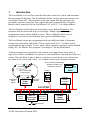
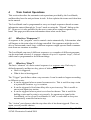
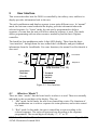
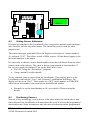
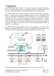
1
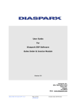
CML Electronics Limited DSS1 LocoShuttle LocoNet Compatible Automatic Train Controller User Manual 1 Introduction The LocoShuttle is a LocoNet controller that takes control of a train, and automates the movement of that train. The LocoShuttle allows realistic train movements to be controlled “hands off”, allowing more train movements that the operators can personally operate at one time. Any engine that can be controlled by a Digitrax throttle can be controlled by the LocoShuttle: DC or DCC, 2 or 4 digit address! The LocoShuttle controls the train according to a pre-defined Sequence. The sequence tells the train what to do at each stage. Simple sequences are preprogrammed; others can be added by users. The LocoShuttle allows up to 4 sequences to be stored, and each may have up to16 individual steps. The LocoShuttle comes pre-programmed with two different kinds of sequence: station stop, and end-to-end shuttle. These can be used “as is”, or others can be programmed using a simple “Learn” mode. More complex sequences can be defined using a PC, for which a free program “Locoanalyse” can be downloaded. Train movements may respond to track sensors or to inputs from other units. A typical use of the LocoShuttle is to operate a train such that it runs and then halts at a sensor. This can allow a train to halt at a station on a track loop, or to run between two ends of an “end to end” track – for example between two terminus stations. Drives a train automatically! Acts like a throttle, and responds to sensors User Constructed Control Panel Throttle Loco Start/ Stop 3r:07 DSS1 SP:70 Pushbutton switch inputs DTM30 Tower Master LED Drive Outputs DCS100/ DB150 Command Station LocoNet BDL168 Sensor Board DAC10 Accessory Decoder DS64 Accessory Decoder SIGM20 Signal Controller point motors DSS1 LocoShuttle User Manual CML Electronics Limited 2008 Page 1of 31 The DSS1 can be used as supplied, or it can be mounted behind a panel. If desired, other pushbuttons can be connected to duplicate the functions of those on the board itself, if these will not be accessible. 1.1 What Is Needed? To use the DSS1 there are a few simple requirements: 1. A railway with trains controlled by a Digitrax command station; 2. A DSS1 LocoShuttle controller; 3. Track or detection sensors in the locations where trains need to halt. These can be of several kinds; they can connect to LocoNet directly, or they can connect to the DSS1 itself. And that's all! 1.2 How to Use This Manual • Section 2 presents a “quick start” guide. This gives a quick run through how to get a train moving under automatic control. • Section 3 describes the connections to the board. • Section 4 describes how automatic operations are controlled and programmed, and gives an overview of the capabilities of the unit. • Section 5 describes the user interface. The various displays that are available are all described, and the pushbutton functions are listed. • Section 6 describes how to program the board using its simple “Learn” function. This allows it to be set up very quickly without needing a PC or any CV programming. • Section 7 describes the advanced capabilities of the unit, and how to configure the board using a PC. A software program for this is available and it will permit a wider range of functions to be set up. Some advanced programming capabilities are described. • Section 8 describes how to connect sensors to the board. Examples of popular types are described. • Section 9 describes how to acquire and dispatch locomotives using Digitrax throttles. 1.3 Safety First! Before beginning to use the DSS1, there are a few safety points to remember: • Hold the board by its edges. By the nature of its construction, some of the pins on the reverse side of the board are sharp and could cause skin abrasions etc if handled incorrectly. DSS1 LocoShuttle User Manual Page 2of 31 CML Electronics Limited 2008 • Allow airflow around the board. Some of its components may run warm in use. Do not obstruct free circulation of air, or allow cloths etc to cover the board. • Do not exceed rated operating voltage. The board could be damaged if an excessive input voltage is applied. The input voltage must not exceed 16v DC. 9V DC is sufficient for normal operation • Do not handle the board when in use. The voltages present on the board (<25v DC) are not considered hazardous to health. However if they should come into contact with sensitive parts of the body (e.g. the mouth) a nasty shock might result. The same is true of the voltage on the rails of a DCC (or other model railway) system, so take care! • Don’t rest the board when operating on the supplied antistatic bag: it is conductive! • Do not power the board from the same transformer winding as the command station. The board should be fed from a separate transformer output. The same transformer can feed several DSS1 units, and can power DTM30 and SIGM20 units. It is believed it can share the same power feed with BDL-16 and BDL-162 boards. • Do not connect the LocoNet feed to the “front” connectors for UP3 or similar panels. This will not cause damage, but it will not allow correct operation. Use a LocoNet connection to the main LocoNet “backbone”. • No connection should be made to the factory configuration port, SK4. DSS1 LocoShuttle User Manual CML Electronics Limited 2008 Page 3of 31 2 “Quick Start” Guide This section is provided as a “heads up” for those who are familiar with LocoNet and Digitrax products, and want to get working with the unit in a simple way. It points to the relevant sections of the manual at appropriate places to avoid duplication. 2.1 Connecting the LocoShuttle The LocoShuttle needs to be mounted in a convenient location. Often this will be in a simple enclosure. As long as the pushbuttons are accessible and the display is visible, anything will do! Section 3.1 describes mounting of the unit. l The LocoShuttle needs a power feed, that MUST NOT be connected to the booster's power input. 9v-12v AC or DC can be used. The supply can be shared with other LocoShuttle units, DTM30 or SIGM20 units. Section 3.2 describes the power requirements. l The LocoShuttle needs a LocoNet connection. This is simply plugged into either or both of the LocoNet sockets in the normal manner. The cable must connect to the normal LocoNet backbone (and NOT to the front of a UP3 or similar panel). Section 3.3 describes the LocoNet connection. 2.2 Positioning Sensors A sensor is needed at each location where the train needs to do something. For a “station stop” operation, a sensor is needed to detect the first part of the train so as to tell it to stop. For an end-to-end “shuttle” a sensor is needed at each end to detect the train's arrival. The sensors must be positioned so that they become “active” when the train is to stop. The train will often “run on” a distance after the sensor: so the sensor will be needed ahead of the final stopping position. Experimentation may be required to find the optimum position. 2.3 Programming “As shipped” The LocoShuttle is shipped with 4 simple sequences programmed into it. These are configured to use the sensors connected to the board inputs. The sequences are as follows: 1 Shuttle between sensors connected to inputs 1 and 2. 1 minute wait at each end. 2 Shuttle between sensors connected to inputs 2 and 4. 1 minute wait at each end. 3 Station Stop at sensor connected to input 1. 1 minute wait. 4 Station Stop at sensor connected to input 2. 1 minute wait. DSS1 LocoShuttle User Manual CML Electronics Limited 2008 Page 4of 31 2.4 Changing the program If those sequences are not appropriate, a new one can be programmed. Either use the on-board “LEARN” feature (see section 6) or use the PC Program “Locoanalyse” available as a free download from our website (see section 7) 2.5 Operating a Train to a Sequence To commence operation of a sequence: • Choose the required sequence by pressing the “sequence” button on the LocoShuttle until the correct one is selected. Each time the button is pressed, the sequence name scrolls across the display then its number is shown. • Using a throttle, start the train running at the right speed to destination sensor. “Dispatch” the loco from the throttle (on a DT400 press LOCO then DISP). • Press and hold the “Loco” button on the LocoShuttle until a beep is heard. The loco number will scroll across the display, and the train is now being automatically controlled. • If it is necessary to adjust the “running” speed, use the “up” and “down” buttons on the LocoShuttle. 2.6 Stopping the Sequence To end automatic operation: • Press and hold the “Loco” button on the LocoShuttle until the display changes to “dsp?” Then release the button, then press and hold it again. A beep will sound, and “dispatched” will scroll across the display. The train is no longer being controlled automatically. • Using a throttle, re-select the locomotive. (On a DT400, press LOCO twice). DSS1 LocoShuttle User Manual CML Electronics Limited 2008 Page 5of 31 3 Connecting The DSS1 This section describes how to connect power, LocoNet and other things to the DSS1. Pay careful attention to the connectors and to the safety guidance here! Up Loco Down Sequence JP1 (view into side of SK5) SK4 2 1 SK3 LED 0 10 9 7 SK2 7 SK5 sensors 7 Loconet Ports SK6 extra switches 0 0 1 2 3 4 5 1 2 3 SK1 power Figure 3.1: DSS1 Connections 3.1 Mounting The DSS1 unit comprises a single circuit board with dimensions 89mm x 102mm as shown in Figure 3.1. It may be mounted onto spacers or pillars using four screws into the four corner holes. 6BA or M2.5mm screws will be ideal if mounting to a metal or plastic panel; no. 4 self tapping screws are ideal if assembling to a “blind” base e.g. plywood or thick plastic. 3.2 Power Connections This is a screw terminal connector which accept wire inputs providing the AC or DC power feed. An ideal arrangement would be to power the DSS1 from a supply that is turned off and on at the same time as the command station power feed. DSS1 LocoShuttle User Manual CML Electronics Limited 2008 Page 6of 31 1 2 3 +12vDC Out DC DC SK1 SK1: 3 pin screw terminal Pin Function Signal Level pin 2 DC power Connects to 9-12v AC or DC input. pin 3 DC power Connect to programming track for configuration pin 1 View into connector from board edge +12v out 12v output if required (for sensors connected to SK5) (not normally required for connection) We recommend a DC power feed to the board. In normal use, SK1 is connected to 9V-12V DC in. It may be connected either way round. In general, the lower the supply voltage the better: the board needs no more than 9v DC for normal operation. This power must not come from the same transformer winding as the command station, or an accessory decoder. The power feed can be shared with DTM30 or SIGM20 units. It is believed that the LocoShuttle may be connected to the same power feed as for BDL16 or BDL162 boards. In normal use the LocoShuttle derives its operating power from the AC/DC input. Typically it consumes up to approximately 100mA from the input. The power feed can be obtained from many sources and should be readily available within the model railway world. Suitable power supplies from Argos are: • 982-7253 (300mA: will usually supply 2-3 LocoShuttle boards); • 982-7538 (1200mA: will supply 5-10 LocoShuttle boards). 3.3 LocoNet These two identical connectors allow for connection to a LocoNet network using conventional 6 pin RJ12 (US style telephone) connectors. The two connectors are wired in parallel: the LocoNet wiring may be connected to either port, or may be daisy-chained through the LocoShuttle. Do not connect via the “front” connectors on a Digitrax throttle panel, e.g. UP3. The board will not function correctly because the Rail_Sync signals are propagated differently on those connectors. DSS1 LocoShuttle User Manual CML Electronics Limited 2008 Page 7of 31 SK2, SK3 Pin 1 2 3 4 5 6 6 pin RJ12 Function RAIL_SYNCLocoNet Ground LocoNet LocoNet + LocoNet Ground RAIL_SYNC+ These signals are defined in the LocoNet Specification which is available from Digitrax. The board decodes the DCC accessory packets from the RAIL_SYNC signals on these connectors. 3.4 External Pushbutton Connections If desired, users can additional push buttons to replace the function of those on the PCB. The pushbuttons should be “push to make, release to break” type and should not be latching in the “down” position. SK1 1 2 3 4 5 View into connector from board edge SK6: 5 pin screw terminal Pin Function Signal Level pin 1 +5v Common return for the 4 switch inputs common below pin 2 Loco Connect the “Loco” pushbutton between here and pin 1 pin 3 Sequence Connect the “Sequence” pushbutton between here and pin 1 pin 4 Up Connect the “Up” pushbutton between here and pin 1 pin 5 Down Connect the “Down” pushbutton between here and pin 1 3.5 Sensor Connections Connector SK5 is provided to allow up to 4 track sensors to be connected to the board. These sensors generate the same LocoNet messages as BDL16 sensors or BD1 sensors connected to DS-54 or DAC10 accessory decoders. This works well with opto sensors such as the IRDOT, and with BD4 detectors. • For “IRDOT” type sensors, the sensor relay output should connect between the sensor input pin and +12v from SK1. DSS1 LocoShuttle User Manual CML Electronics Limited 2008 Page 8of 31 • For BD4 sensors, the BD4 pins connect via a ribbon cable. A cable is available from CML electronics if required. Connector type Pin 1 3 5 7 9 10 pin header Function Input 1 Input 2 Input 3 Input 4 Unused Pin 2 4 6 8 10 Function GND GND GND GND Unused Sensor level Active if +12v Inactive if 0v 3.6 Test Function The LocoShuttle has a “self test” function to ensure that any inputs have been wired correctly. It is recommended that this test be used to establish that the wiring is correct. This test is invoked by powering up the board while the “Loco” pushbutton switch mounted on the board is pressed. This has the following effect: 1. The display scrolls “LocoShuttle board xx” (xx= serial number). 2. The display goes blank. 3. Pressing the pushbutton will cause a display digit to light with “b”: • “Loco” button lights the 1st digit; • “Sequence” button lights the 2nd digit; • “Up” button lights the 3rd digit; • “Down” button lights the 4th digit. 4. Activating a sensor input will cause a display digit to light with “S”: • Sensor input 1 lights the 1st digit; • Sensor input 2 lights the 2nd digit; • Sensor input 3 lights the 3rd digit; • Sensor input 4 lights the 4th digit. DSS1 LocoShuttle User Manual CML Electronics Limited 2008 Page 9of 31 4 Train Control Operations This section describes the automatic train operations provided by the LocoShuttle, and describes how the unit performs its task. It also explains the terms used elsewhere in the manual. The LocoShuttle can be programmed to carry out simple sequences based on some information entered through its “Learn” mode or using the “Wizard” dialog on the PC. However it is also possible for the user to enter more complex sequences by hand. This page provides some information about what can be done. 4.1 What is a “Sequence”? A sequence is the “program” used to control a train automatically. It determines what will happen to the train when it is being controlled. One sequence might be used to drive a train around a track loop; a different sequence might operate small commuter train from one terminus to another. The LocoShuttle can store 4 different sequences: so a number of different programs can be stored and selected. A sequence consists of up to 16 separate “steps”, each of which can be programmed to do different things. 4.2 What is a “Step”? The basic “element” of a train control sequence is a sequence step. Each step is defined separately and has two key pieces of information: • How it is triggered; • What it does when triggered. The “Trigger” part defines when a step executes. It can be made to happen according to different events: • It can be triggered when a sensor becomes active. This is useful to stop a train at a particular location: e.g. in a station. • It can be triggered a fixed time delay after a previous step. This is useful to start a train again in a station. • It can be triggered when a point is set closed or thrown. This is useful for holding a train until a point is set correctly, for operators to signal to the LocoShuttle, or for several LocoShuttles to “talk” to each other to keep two automatically controlled trains in step. The “Action” part chooses what the step does after it has been triggered. There are, again, several possible choices: DSS1 LocoShuttle User Manual Page 10of 31 CML Electronics Limited 2008 • It can stop its train • It can start its train, in the same or a different direction. It can also start the train in the direction it was first running when acquired by the LocoShuttle, or the opposite direction from that. These last two might be used on complicated routes. • It can set a locomotive function for a programmed number of seconds. This could be used in sound equipped locos to “whistle” before leaving a station. • It can end the sequence and dispatch the loco. The loco can then be acquired by other throttles. • It can set a point to closed or thrown. This might be used to control the track ahead of the train, to choose an arrival platform for example. 4.3 More Complicated Examples To put together more complicated sequences, some further variations can be selected. • A sensor trigger can be made to happen only if the trigger condition happens several times. If programmed to happen on the 5th trigger, the first 4 times the sensor is occupied will be counted but the train will only be affected by the 5th trigger. • A step can be blocked from triggering until another step has triggered. This might be useful to prevent erroneous operation for noisy sensors caused by track pickup problems. For example changing a train’s direction in a terminus should only happen once per visit to the station. • It may be desired to have TWO triggers: e.g. wait in a station for 30seconds, then start when point 55 is set to Thrown. To do this put in an intermediate step that has no real effect e.g. o delay 30s then set point 2048 Thrown; o trigger when point 55 closed then restart train in same direction 4.4 Starting off A sequence starts to run when a train is acquired. However it doesn’t know, initially, where it is in the sequence. For example, in an end-to-end shuttle, it does not know which end will be reached first: that depends on the direction the train is started in by the operator. This is why, when the sequence first runs, the rightmost two digits show “--”. When it first sees a sensor step get triggered – in this case by the first sensor it reaches – it sets its position in the sequence. Thereafter it tries to follow the sequence in order. If an event does happen out of order, it will change to that step number but only if it is an unambiguous change. Steps triggered by point setting will not change sequence the order. DSS1 LocoShuttle User Manual CML Electronics Limited 2008 Page 11of 31 4.5 When Switching Off and On The LocoShuttle can “remember” its loco number when power is switched off. This allows the LocoShuttle to be assigned a loco and then keep control of it between operating sessions. When the LocoShuttle does this it remembers the correct locomotive number, the correct running speed and the current direction. It does not store what “step” it was on in the sequence: the sequence will have to be re-started. • To remember a loco number: o Before turning off, halt or stop the sequence by pressing the sequence button. (You wouldn’t want to turn power off with trains running!) o Switch off the railway as normal. • To re-start the sequence next time: o After powering up, the LocoShuttle will scroll the loco number and then be in a “stopped” state. The display for sequence 3 would be “3h.—“ o Start the sequence by long pressing the sequence button. o The train will begin to run at its previous speed and in its previous direction. Because the sequence is restarted, sometimes the train direction may not be ideal. For example if the sequence was stopped while the train was waiting in a terminus, when it restarts it will run into the buffers in the terminus. This can be corrected by stopping the sequence and changing direction. It can be avoided by always stopping the sequence before powering off while the train is moving. DSS1 LocoShuttle User Manual CML Electronics Limited 2008 Page 12of 31 5 User Interface This section describes how the DSS1 is controlled by the railway user, and how its display provides information back to the user. The unit's pushbuttons and displays operate in two quite different ways. In “normal” mode, the unit can control trains and the display provides information about the selected sequence. In “Learn” mode, the unit can be programmed to define a sequence of events that the unit will follow when the sequence is used. This mode allows programming with no other resources needed beyond the basic Digitrax controller. The board has four pushbuttons and a 4 digit LED display. These form the basic “user interface”: through them the user control the LocoShuttle, and gets feedback information from the LocoShuttle. For some functions, the normal LocoNet throttle is also used. Up Locomotive Down Sequence Step Number (1 to 16) sequence Number (1 to 4) F: forward r: reverse h: halted -: not running Figure 5.2: User Interface 5.1 What is a “Mode”? There are three “modes” that the board can be in when it is used. These are normally indicated by the second digit of the display. They are: 1. “Idle” mode. In this mode, the unit is not controlling a train. The functions of the pushbuttons are to select a sequence for train operation, and to take control of a train. 2. “Run” mode. In this mode, the unit is controlling a train according to the selected sequence. The train will start and stop according to the sequence programmed. The second digit will display “r”, “F” or “h”. DSS1 LocoShuttle User Manual Page 13of 31 CML Electronics Limited 2008 3. “Learn” mode. In this mode, a sequence is programmed using simple display prompts. The user selects the sensors to which the train will respond by putting a loco onto the appropriate pieces of track; other selections are made using “switch” operations using a throttle. The second digit will display “L”. 5.2 Pushbuttons The unit has four pushbuttons. These each have a number of functions depending on operating mode. l The LOCO button is associated with selecting a locomotive to be controlled by the LocoShuttle, and releasing a locomotive from automatic control. l The SEQUENCE button is normally associated with selecting an operating sequence, and with starting or stopping that sequence. l The UP and DOWN buttons, when a train is running, allow the running speed of the locomotive to be changed. When a sequence is stopped, the “Down” button can be used to change the train’s direction. In “Learn” mode they are used to set the train's acceleration rate, and to choose the sequence type to be learned. Please note that the buttons sometimes have a different function if pressed for a long period, as opposed to being pressed and released momentarily. Where a “long” press is required, the button should be pressed and held for approximately 1 second. 5.3 Display The LocoShuttle has a four digit display. This is used to display both numbers and simple letters. Most of the time this displays information about the current mode. If desired, the display can be covered using transparent red filter. These are readily available. 1st digit Displays the sequence number (1-4) 2nd digit Displays the operating mode: “-”: idle mode; not executing a sequence “F”: run mode; executing a sequence, train running forward “r”: run mode; executing a sequence, train running in reverse “h”: run mode, but train temporarily halted. “L”: Learn mode; a new sequence is being programmed. (when the sequence is stopped, the last 3 digits say “stp” DSS1 LocoShuttle User Manual CML Electronics Limited 2008 Page 14of 31 The central “dot” is usually lit to separate the two halves of the display 3rd, 4 digits In “idle” mode: these digits display “--” In “run” mode: these digits display the next expected step number (1-16). If this is not yet known, displays “--”. In “Learn” mode: these display the sequence type being learned, the acceleration rate to be used, and the step being learned. The display can also “scroll” a simple text message. Some of the characters are formed in a strange way but the messages are still clear. When text is scrolled it begins at the right hand side of the display and scrolls across to the left. 5.4 When in “Idle” Mode The board power up in “Idle” mode. It is not controlling a locomotive; it is waiting for the user to choose a sequence, and assign a locomotive to it. The following actions using the pushbuttons on the board are possible in Idle mode. The key to understanding what’s happening is to watch the display! Action (at power up) (at power up, with a stored loco number) press & release Sequence button press and release Loco button “long” press Loco button Meaning & Display Scrolls the sequence name then displays the sequence number: e.g. 2-.-(the 3 dashes indicate Idle mode) As above, but with “L” as the right hand digit e.g. 3—L This indicates the LocoShuttle is trying to retrieve a locomotive from the command station; only be seen if the LocoShuttle is powered up before the command station. Pressing the Loco key abandons retrieving the stored loco Moves to the next sequence. Scrolls the sequence name then displays the sequence number: e.g. 3-.-Scrolls “no loco” then normal display i.e. 3-.-- Attempts to acquire a locomotive. If successful scrolls “Loco xx” where xx is the DCC cab number of the loco; then enters “Run” mode (see section 5.5). If unsuccessful, scrolls “fail no loco” then normal display. “Long” press Sequence entry to LEARN mode. Display 3L.?? Button (see section 5.6 for next steps) DSS1 LocoShuttle User Manual CML Electronics Limited 2008 Page 15of 31 5.5 When in “Run” mode After a locomotive has been acquired, the board begins automatic control. This is “run” mode. Action Meaning & Display on entering Run mode: 3F.-- or 3r.-F or r indicate forward or reverse running of the loco -- indicate sequence step not yet known short press Loco button scrolls “Loco xx” where xx is the DCC cab number of the loco; then normal display (after a sensor tripped) Displays sequence position, e.g. 3F.04 Short press Up button increases loco speed by 1 step. Momentarily displays “sp.nn” where nn is the % of full speed Short press Down decreases loco speed by 1 step. Momentarily displays button “sp.nn” where nn is the % of full speed Short press Sequence Temporarily halts train. Display shows “3h.04” i.e. step button number still shown. Short press Sequence Resume normal running. Display shows “3F.04” button while halted Long press Sequence Stops sequence, with train still assigned. Sequence step is button reset. Long beep. Display 3stp Long press Down Changes train running direction. Display scrolls “direction button while stopped reverse” or “direction forward”. Long press Sequence Resume normal running. Display shows “3r.--” button while stopped Long press Loco button 1st stage of dispatching loco. Display shows “dsp?” meaning “do you want to dispatch?” no button pressed Resumes normal Run mode. Display 3r.—or sequence within 5s number Long press Loco button Confirms; loco is dispatched and unit re-enters idle mode. Displays “dispatched” then normal display 3-.-- 5.6 “Learn” Mode “Learn” mode is used to carry out simple programming without needing a PC. Simple sequences for end-to-end shuttle or station stops can be programmed. All that is needed is the LocoShuttle, the Digitrax command station, a throttle and the track sensors that will detect the train “stopping” positions. DSS1 LocoShuttle User Manual CML Electronics Limited 2008 Page 16of 31 From idle mode: long press Sequence button long press Sequence button up or down button long press Sequence button up or down button long press Sequence button at end of LEARN Displays shown 2L.?? Confirms entry to LEARN mode. Display scrolls “shuttle” then shows “2L.t0”. This means sequence 2, learn mode, type 0 Choose a different learn type. Currently only 0 (shuttle) or 1 (station stop) are available. Enters “choose acceleration”. Display 2L.A4 selects a different acceleration value (0 seconds to 9 seconds). This is how long the train takes to accelerate from zero to 50% of full speed. Unit collects details for the selected sequence type. The display will scroll a message asking for sensor numbers, or other numbers. For sensor numbers: occupy the track with a loco for other numbers: dial up the required answer as a switch number on a throttle and press “thrown”. See examples in section 6 below. long beep; unit restarts DSS1 LocoShuttle User Manual CML Electronics Limited 2008 Page 17of 31 6 Preprogrammed Operation This section describes how to use the LocoShuttle in its two “preprogrammed” modes: station stop mode, and shuttle mode. In these modes the logic needed to operate the train has already been programmed: all that needs to be provided into the unit are sensor details. A simple “Learn” mode gets that information simply from the user. 6.1 How to Operate a Sequence This section describes briefly the operations needed to acquire a loco, and control a sequence. 6.1.1 Before loco acquired 1. Select the required sequence (1-4) by pressing the “Sequence” button until it is selected. The sequence name scrolls across the display as the step is changed, then the left hand digit shows the sequence number. 2. Using a throttle, start the train running on the track loop at the required speed. 3. Dispatch the loco from the throttle. Using a DT400 that would involve pressing the LOCO then DISP buttons. 4. Press the “Loco” button on the LocoShuttle for 1 second. A long bleep will be sounded, and the locomotive number will be scrolled across the display. After that the second digit of the display will change to “F” or “r”, depending on which direction the train is running. 5. The train is now under automatic control and will stop at the station when the sensor input is detected. 6.1.2 After loco acquired • To stop the sequence temporarily, pres the “sequence” button. To restart it again, press the “sequence” button again. • To speed up or slow down the train, press the “up” or “down” buttons. Its speed will go up or down by one notch. Press as often as needed to get the required speed. The new speed (% of full speed) scrolls across the display. • To reverse the train direction: (assume that it is sequence 2 running; the left hand digit will be “2” in this case) 1. Start with the train running; the display will show “2F.01” while running forwards. 2. Press the “Sequence” button on the LocoShuttle for 1 second. A long bleep will be sounded, and the train will slow down and stop. The display will show “2stp”. DSS1 LocoShuttle User Manual CML Electronics Limited 2008 Page 18of 31 3. Press the “Down” button on the LocoShuttle for 1 second. Two short beeps will sound, and the display will scroll “direction reverse”. Then the display will go back to showing “2h.--”. 4. Press the “Sequence” button on the LocoShuttle for 1 second. A long bleep will be sounded, and the train will speed up again but in the other direction. The display will now show “2r.01”. 6.1.3 Finishing Automatic control 1. Press the “Loco” button on the LocoShuttle for 1 second. The display will say “dsp?”. Then long press the “Loco” button again. A long beep will be sounded, and “dispatched” will scroll across the display. 2. Using a throttle, re-acquire the loco. With a DT400 that involves pressing its LOCO button twice. 6.2 Station Stop In “station stop” mode, a train will drive around a loop of track and then stop at a station. It can stop every time it arrives, or every several visits. The length of the halt can be selected. station 1 sensor 1 6.2.1 Locating the Sensor For this sequence, a sensor is needed to detect that the head of the train has arrived at the correct part of the station. Generally this will mean a sensor towards the end of the platform, positioned so that when the sensor operates and the train decelerates to stop, it halts in the intended position. Some experimentation with sensor position given the train speed and acceleration rates will be needed. 6.2.2 Programming the LocoShuttle Step Operation 1. Use “Sequence” button to choose the sequence to be learned; e.g. sequence 2 Long press “sequence” button. 2. DSS1 LocoShuttle User Manual CML Electronics Limited 2008 Display 2-.-LRN? Page 19of 31 3. 4. 5. 6. 7. 8. 9. 10. Long press “sequence” again. LocoShuttle enters “learn” mode (any other button will cancel the LEARN operation) press “up” button long press “sequence” button. The LocoShuttle now needs an “acceleration” value. Use “up” or “down” buttons to choose an acceleration value. This is the time (0 to 9 seconds) to ramp up or down from 50% of full speed long press “sequence” button. The LocoShuttle now needs the sensor number for the station stop sensor Put a train onto the rails at the sensor to occupy it. The LocoShuttle stores the number The LocoShuttle now needs to know the number of “visits” to the station before the train stops (1=every visit; 5 = every 5th visit etc) To choose every 5th visit, use a throttle to set switch 5 to THROWN. The LocoShuttle now needs to know the number of seconds the train should wait at the station before moving off scroll “shuttle” then 2L.t0 scroll “station stop” then 2L.t1 2L.A3 2L.A7 scroll “station sensor” then 2L.18 3 beeps scroll “pass counter” then 2L.19 beep scroll “halt time?” then 2L.22 beep To choose every 25 seconds, use a throttle to set switch 25 to THROWN. That’s it! The LocoShuttle restarts, and is ready to execute the 2-.-sequence. Assign a loco and go! When the LocoShuttle has scrolled a message, pressing the “Loco” button causes it to re-scroll the message. Thus if a message is missed, it is possible to see it again. 6.3 Shuttle station 1 sensor 1 station 2 sensor In “shuttle” mode, a train moves from end-to-end of a run of track and halts at each DSS1 LocoShuttle User Manual CML Electronics Limited 2008 Page 20of 31 end. It then changes direction and runs to the other end, halting again. The length of each halt can be selected. 6.3.1 Locating the Sensors For this sequence, a sensor is needed at each terminus to detect that the first part of the train has arrived at the correct part of the station. Generally this will mean a sensor towards the end of the platform, positioned so that when the sensor operates and the train decelerates to stop, it halts in the intended position. Some experimentation with sensor position given the train speed and acceleration rates will be needed. If optical sensors are used, no particular problems will be experienced. However if electrical occupancy detection sensors are used, the sensors need to detect the “rear” end of the train as well as the front end. One end will normally have the loco and decoder; however the other may not have a decoder but it still needs to trigger the sensor. Using a “resistor wheelset” is a common solution. In this approach, a resistor is attached across the last axle of the train – possibly in a non motorised DMU body. The block detector detects the resistor, and the sensor is reported as occupied. Many track sensors need a resistance between 1K and 10K to operate correctly. CML Electronics can’t help with this, but it is a recognised approach and a lot of advice should be available through the internet. 6.3.2 Programming the LocoShuttle Step Operation 1. Use “Sequence” button to choose the sequence to be learned; e.g. sequence 3 Long press “sequence” button. 2. Long press “sequence” again. LocoShuttle enters “learn” 3. 5. 6. 7. mode (any other button will cancel the LEARN operation) long press “sequence” button. The LocoShuttle now needs an “acceleration” value. Use “up” or “down” buttons to choose an acceleration value. This is the time (0 to 9 seconds) to ramp up or down from 50% of full speed long press “sequence” button. The LocoShuttle now needs the sensor number for the 1st station stop sensor DSS1 LocoShuttle User Manual CML Electronics Limited 2008 Display 3-.-LRN? scroll “shuttle” then 3L.t0 3L.A3 3L.A4 scroll “end 1 sensor?” then 3L.18 Page 21of 31 8 10 8 10 Put a train onto the rails at the sensor to occupy it; the LocoShuttle stores the number. The LocoShuttle now needs to know the number of seconds the train should wait at the station before moving off To choose every 25 seconds, use a throttle to set switch 25 to THROWN The LocoShuttle now needs the sensor number for the 2nd station stop sensor Put a train onto the rails at the sensor to occupy it; the LocoShuttle stores the number. The LocoShuttle now needs to know the number of seconds the train should wait at the station before moving off 3 beeps scroll “halt time?” then 3L.22 1 beep scroll “end 2 sensor?” then 3L.26 3 beeps scroll “halt time?” then 3L.30 1 beep To choose every 15 seconds, use a throttle to set switch 15 to THROWN That’s it! The LocoShuttle restarts, and is ready to execute the beep, then sequence. Assign a loco and go! restarts. 3-.-- DSS1 LocoShuttle User Manual CML Electronics Limited 2008 Page 22of 31 7 Configuring with a PC For many users, the “Learn” mode of programming will be sufficient. However the unit has been designed to have more advanced capabilities, that can be realised through more complex programming. The LocoShuttle will support programming through LocoNet; a simple PC application “Locoanalyse” is available free of charge from our website for this. Visit http://www.cmlelectronics.co.uk/products/locoanalyse.htm for details. The program includes a “help” file to explain its operation. 7.1 LocoAnalyse The “Locoanalyse” program is a simple PC application for defining, editing, storing and programming our products. Using Locoanalyse it is possible to store the settings for several board types, to make changes to them using a graphical interface, and to program the boards while connected to a “live” LocoNet through a “LocoBuffer” or similar interface. 7.2 Defining Programs Locoanalyse provides a screen in which the settings for a sequence can be entered. It shows the settings for all 16 sequence steps and provides visual control to make changes to them. In this way, the user can assign whatever programming is needed to a sequence. Locoanalyse also provides a programming “Wizard” to define simple “Station Stop” and “Shuttle” sequences. These have the same capability and programming as those defined by the on-board “Learn” method. 7.3 Advanced Capabilities Through LocoAnalyse, a number of more advanced capabilities of the board are available. This allows more complicated sequences to be defined. It is up to the user how these are used, and CML Electronics cannot provide programming service for users. Our support extends as far as making sure the product is functioning properly1 Sequence Steps can be triggered to happen according to the following circumstances: • When a train sensor is triggered. This is the most common form of trigger. The trigger can have a counter, so that the train has to “visit” a certain number of times. The trigger can be blocked from happening until something else has triggered, usually used to prevent noisy sensors upsetting operations. DSS1 LocoShuttle User Manual CML Electronics Limited 2008 Page 23of 31 • After a delay from the last step. This is used to set “waiting periods” in stations etc. • When a point is set to closed or thrown. This can be used for different purposes. It can be used to hold a train in a station until the track is set in its favour. It can also be used for the operator to force a train to stop or wait by setting a point. o The state of the point is stored whenever it changes. When a step is reached that has a point number trigger, the state of that point is looked up. If the point isn’t in the required state, the LocoShuttle will wait until the point changes. o The settings of points aren’t known immediately after a sequence is selected. It is best if all of the points important to a sequence are manually changed before starting the sequence, so that the LocoShuttle can memorise them. Sequence steps can achieve the following effects: • The train can be stopped and started, with defined acceleration rates; • A locomotive function can be turned on for a defined number of seconds. This could be used with sound-equipped locomotives to “whistle” before a train leaves a station. • The locomotive can be dispatched, and the sequence ended. This will return the train to be available for manual control with a throttle. • A point number can be set to THROWN or to CLOSED. This is useful to control points, and to signal to other LocoShuttle units. When a sequence needs to set several points one after the other, setting of each point is defined as a separate step. The first of these is assigned a “normal” trigger event (e.g. a train occupying a sensor); subsequent ones should be programmed as “trigger after 1 second delay”. For example, if points 49 & 50 are both to be set closed when sensor 27,13 is occupied by a train: • Trigger when sensor 27,13 occupied; Action set point 49 CLOSED • Trigger after 1 second delay; Action set point 50 CLOSED If it is necessary to set several points – for example to get out of a yard onto a main line – consider using routes controlled by a DCS100 (Digitrax) or DTM30 (CML Electronics) to set all of the points from a single switch instruction. DSS1 LocoShuttle User Manual CML Electronics Limited 2008 Page 24of 31 7.4 Advanced Programming Example In this example, two LocoShuttle units are to be used to control two trains on a single loop of track. The two trains are to pass each other in two loops; it needs to be robust to which train arrive first in either loop. The track layout in the example consists of 4 points, and 4 track sensors. The sensor need to be positioned so that when tripped, the trains will sop before running onto their respective points. The points will be controlled by the shuttles, so must be controlled by DCC accessory decoders. 3 D X Y T C 4 T C C Track sensors A-D; points 1-4 X T C T C A 1 B Y 2 7.4.1 Starting Off The two trains are positioned as shown, and the points all set so the trains can reach their first stopping places (i.e. 1=C, 3=T, 2=C, 4=T ). The trains are started off then dispatched from their throttles, and acquired into the LocoShuttles. Thereafter, the LocoShuttles must provide the correct behaviour. 7.4.2 Programming To enable this to work correctly, one LocoShuttle must be a “master” and controlling the other. The other acts as a “slave” and simply does what it is told. It doesn’t matter which; in this example X is the slave and Y the master. DSS1 LocoShuttle User Manual CML Electronics Limited 2008 Page 25of 31 So that the master LocoShuttle knows that the other is doing, the “slave” unit will signal when train X has reached sensors A and D respectively. It will do that by setting switch addresses 2000 and 2001 to “thrown”. The “master” LocoShuttle will interpret these accordingly. Both trains set the points “behind” them when they have run through them. Train X will run around its loop, stopping at sensors A and D. It will then restart its journey when points 1 and 4 are changed. Train Y will run around its loop till its stop sensor, and when it sees the point message (indicating that the other train has reached its endpoint) it will set the points for the next stage of the journey. It doesn’t matter which train arrives first! 7.4.3 Step 1 2 3 4 5 6 7 8 9 10 Programming for train “X” Details When sensor A triggered, stop Set point 4 = Thrown (i.e. against it for next step) Set phantom point 2000 to Thrown When point 1 = C, Set phantom point 2000 to Closed Start train in original direction When sensor D triggered, stop Set point 1 = Thrown (i.e. against it for next step) Set phantom point 2001 to Thrown When point 4 = C, Set phantom point 2001 to Closed Start train in original direction 7.4.4 Step 1 2 3 4 5 6 7 8 9 10 Programming for Train “Y” Details When sensor B triggered, stop Set point 3 = Thrown (i.e. against it for next step) When point 2000 = T, Set point 1 = closed Set point 2 = closed Restart train in same direction When sensor C triggered, stop Set point 2 = Thrown (i.e. against it for next step) When point 2001 = T, Set point 4 = closed Set point 3 = closed Restart train in same direction DSS1 LocoShuttle User Manual CML Electronics Limited 2008 Page 26of 31 8 Connecting Sensors To use this product effectively, sensors are needed to detect the presence of trains at certain locations. Sensors can be of many types; there are two distinct groups of sensor types and either can be used. l Infra-red detectors and even microswitches can be used to detect a train at a particular location. These “positional” detectors will detect the presence of anything on the rails at that point, and could be triggered by hands or other non-railway objects. l Occupancy detectors measure a current flow in the rails. This detects a train by its motor or lighting load. They are not sensitive to sunlight or objects waving in the vicinity, but they do need the track to be split into different electrical sections. If it is necessary to detect a train running backwards – e.g. a Diesel Multiple Unit running a shuttle sequence – then some kind of electrical load on the unpowered rear car will be needed. If sensors are already present on the railway, they may already be connected to LocoNet. Examples might include existing BDL168 occupancy detector units, or infrared sensors connected via an accessory decoder such as a DAC10/DS54/DS64. If the sensors are already connected to LocoNet, they can be used “as is”. If not, new sensors can be wired to existing accessory decoders or direct to the LocoShuttle unit. 8.1 Example: Digitrax BD-4 The Digitrax BD4 is a simple 4 channel electrical occupancy detector. It is connected in series with the track power feeds, and determines if a train is present in each section by measuring the current fed to each section. If it detects a current flow, it declares a train to be present. The BD4 has a simple 10 way ribbon cable connector, and can be connected directly to SK5. CML Electronics supplies a suitable ribbon cable if required. It isn’t necessary to have block detectors covering the whole railway: just those locations where trains need to be stopped. So having most of the track connected straight to the booster, with only two small sections detected by block detectors, would be fine. DSS1 LocoShuttle User Manual CML Electronics Limited 2008 Page 27of 31 10 9 red stripe 2 1 SK5 sensors 7 0 7 0 12 3 SK2 7 0 SK3 booster power feed 2 1 2 1 LED connector BD4 booster rail A rail B 8.2 Example: IRDOT2 The Heathcote Electronics “IRDOT” sensor can be used with the DSS1. The IRDOT is an optical sensor, and uses reflected infrared light to detect rolling stock position. Because it is an optical sensor, it is good for detecting the exact position, which is commonly needed for precise stopping. The IRDOT-2 has a relay contact output and is ideal for this application. The relay contact should be connected between pin 1 of SK1 and the appropriate sensor input. The relay contact should be closed when the sensor is active. DSS1 LocoShuttle User Manual CML Electronics Limited 2008 Page 28of 31 10 9 2 1 SK5 sensors 7 0 7 0 12 3 SK2 IRDOT-2 7 0 SK3 8.3 Setting Sensor Addresses If sensors are attached to the LocoShuttle, they can generate normal sensor messages onto LocoNet just like any other sensor. This means they can be used for other purposes too. The sensor messages generated follow the Digitrax convention of “sensor number 116, on board 1-256”. This allows a total of 4096 sensors. All that has to happen is for the board numbers to be unique. It is necessary to choose a sensor board number value that is different from any other sensors used on the railway. The value is factory programmed to board number 17 but can very simply be changed. This can be done in two ways: • Via a PC, using the “locoanalyse” program; • Using a normal LocoNet throttle. To use a throttle, remove power from the LocoShuttle. Then reapply power to the LocoShuttle with both the “Loco” and “Sequence” pushbuttons held down. The display will be set to “Sen?”. Then simple set a DCC switch number to THROWN, where the switch number is the same as the desired board number. • Example: to set the board number to 68, set switch 68 Thrown using the throttle. 8.4 Positioning Sensors Sensors, of any technology, need to detect at the place where the train needs to stop. Once detected, the LocoShuttle will ramp down the speed to zero at the programmed acceleration rate. Some locomotives may also have acceleration values programmed DSS1 LocoShuttle User Manual CML Electronics Limited 2008 Page 29of 31 into the decoders. The result of all this is that the train stopping position may be a little along the track from where the sensor detected it. Conduct experiments to choose the optimum combination of sensor position and acceleration settings. 8.5 Testing Sensor Inputs The LocoShuttle has a “self test” function to ensure that any inputs have been wired correctly. It is recommended that this test be used to establish that the wiring is correct. This test is invoked by powering up the board while the “Loco” pushbutton switch mounted on the board is pressed. This has the following effect: 1. The display scrolls “LocoShuttle board xx” (xx= serial number). 2. The display goes blank. 3. Activating a sensor input will cause a display digit to light with “S”: • Sensor input 1 lights the 1st digit; • Sensor input 2 lights the 2nd digit; • Sensor input 3 lights the 3rd digit; • Sensor input 4 lights the 4th digit. 8.6 Using Existing BDL168 Sensors If your railway already has BDL168 track sensors, these can be used “as is”. No additional connections will be needed: the LocoShuttle will detect the messages from those sensors through LocoNet. If BDL168 sensors are used, it is recommended that the option switch 9 on each BDL168 should be set “closed”. This prevents all sensors being set to “occupied” of track power is removed – as happens if a short occurs on the railway. Setting this options switch to “closed” will cause no adverse effects. Consult the BDL168 manual page 12 for details. DSS1 LocoShuttle User Manual CML Electronics Limited 2008 Page 30of 31 9 Acquiring and Dispatching Locomotives To use the LocoShuttle effectively, it is important to know how to “acquire” and “dispatch” locomotives. Full details are covered in the Digitrax throttle documentation: see section 14.1 in the “Super Chief” manual. Digitrax supports the concept of “dispatching” and “acquiring” locomotives so that they can be passed between train operators on a railway. The LocoShuttle uses this mechanism to get control of a train. Think of dispatching for a moment as putting a train into a “special place” in the Command station: • When a user wants to hand control of a train to someone else, they put it into the “special place” • When another user wants to take control of that train, they take it from the “special place”. In practice the “special place” doesn’t mean any particular location on the railway; the train can be anywhere on the railway, and it can be moving. • Using a DT400 throttle, a user controlling the train puts in into the “special place” by pressing LOCO then DISP on the throttle. They are no longer controlling it. • To take control of that loco into the LocoShuttle, “long” press the “Loco” button on the LocoShuttle for about a second. There will be a beep, and the locomotive number will scroll across the display. The LocoShuttle has taken the train from the “special place” and is not controlling it. • When automatic control has finished, long press the “loco” button twice on the LocoShuttle. There will be a “beep” and the display will scroll “dispatched”. The LocoShuttle has put the train into the “special place” and is not controlling it. • To take it back into manual control, press LOCO then LOCO again on the throttle. It is now back in manual control. DSS1 LocoShuttle User Manual CML Electronics Limited 2008 Page 31of 31 CML Electronics Limited 18 Nickleby Road Clanfield Waterlooville Hampshire PO8 0RH UK Telephone: 02392 599570 Email: [email protected] Web page: www.cmlelectronics.co.uk Manual Rev: 1 Designed And Manufactured in the UK CML Electronics Limited 2008 All Rights Reserved