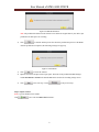
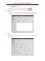
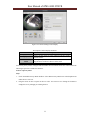
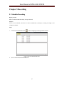
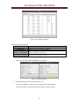
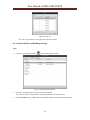
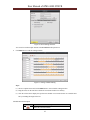
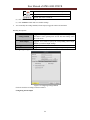
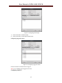
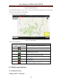
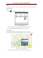
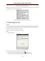
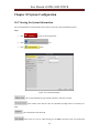
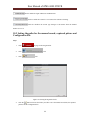
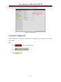
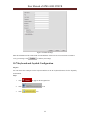
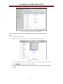
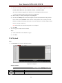
1
iVMS-4200 PCNVR User Manual Version 1.02 User Manual of iVMS-4200 PCNVR Table of Contents CHAPTER 1. OVERVIEW .................................................................................................................... 5 1.1 DESCRIPTION ......................................................................................................................................... 5 1.2 RUNNING ENVIRONMENT ...................................................................................................................... 5 1.3 CONVENTIONS ....................................................................................................................................... 6 CHAPTER 2 STARTING IVMS-4200 PCNVR ..................................................................................... 6 2.1 USER LOGIN .......................................................................................................................................... 6 2.2 WIZARD FOR IMPORTING DEVICE .......................................................................................................... 6 2.3 CONTROL PANEL AND MAIN MENU BAR INTRODUCTION .................................................................... 16 2.4 ACCOUNT MANAGEMENT .................................................................................................................... 18 CHAPTER 3 ADDING FRONT-END DEVICES FOR MANAGEMENT AND RECORDING ........ 20 3.1 CAMERA ADDING ................................................................................................................................ 20 3.2 REMOTE MANAGEMENT ...................................................................................................................... 22 3.2.1 Remote Configuration ................................................................................................................. 22 3.2.2 Camera Settings .......................................................................................................................... 30 CHAPTER 4 LIVE VIEW ................................................................................................................... 36 4.1 BASIC OPERATIONS IN LIVE VIEW ....................................................................................................... 37 4.2 CAPTURE IN LIVE VIEW....................................................................................................................... 41 4.3 PTZ CONTROL IN LIVE VIEW .............................................................................................................. 42 CHAPTER 5 RECORDING................................................................................................................. 47 5.1 SCHEDULE RECORDING ....................................................................................................................... 47 5.2 MANUAL RECORDING ......................................................................................................................... 50 CHAPTER 6 PLAYBACK ................................................................................................................... 52 6.1 NORMAL PLAYBACK............................................................................................................................ 52 6.2 EVENT PLAYBACK ............................................................................................................................... 55 6.3 SIMULTANEOUS PLAYBACK ................................................................................................................. 56 6.4 INSTANT PLAYBACK ............................................................................................................................ 57 CHAPTER 7 RECORD FILE EXPORTING ...................................................................................... 58 7.1 EXPORTING RECORD FILES .................................................................................................................. 58 7.2 EXPORTING VIDEO CLIPS .................................................................................................................... 59 CHAPTER 8 EVENT MANAGEMENT AND ALARM I/O SETTINGS ........................................... 60 2 User Manual of iVMS-4200 PCNVR 8.1 ALARM SETTINGS ................................................................................................................................ 60 8.1.1 Manually turn on/off alarm output .............................................................................................. 60 8.1.2 Alarm Parameter settings ............................................................................................................ 60 8.1.3 Alarm Schedule and Handlings Settings ..................................................................................... 62 8.2 CONFIGURING MOTION DETECTION .................................................................................................... 66 8.3 CONFIGURING TAMPERING ALARM ..................................................................................................... 68 8.4 CONFIGURING VIDEO LOSS ................................................................................................................. 70 8.5 CONFIGURING PIR ALARM .................................................................................................................. 72 8.6 CONFIGURING WIRELESS ALARM ........................................................................................................ 73 8.7 CONFIGURING EMERGENCY ALARM .................................................................................................... 74 8.8 CONFIGURING EXCEPTIONS ................................................................................................................. 76 8.9 VIEWING ALARM OR EVENT INFORMATION ......................................................................................... 77 CHAPTER 9 MANAGING E-MAP ..................................................................................................... 79 9.1 ADDING AN E-MAP .............................................................................................................................. 79 9.2 THE HOT SPOT FUNCTION ................................................................................................................... 80 9.2.1 Adding a Hot Spot ....................................................................................................................... 80 9.2.2 Editing a Hot Spot ....................................................................................................................... 83 9.3 THE HOT REGION FUNCTION ............................................................................................................... 84 CHAPTER 10 SYSTEM CONFIGURATION ..................................................................................... 86 10.1 VIEWING THE SYSTEM INFORMATION ................................................................................................ 86 10.2 GENERAL CONFIGURATION................................................................................................................ 87 10.3 SETTING THE PATHS FOR THE MANUAL RECORD, CAPTURED PICTURE AND CONFIGURATION FILE ...... 88 10.4 SETTING THE NETWORK INFORMATION ............................................................................................. 89 10.5 ALARM SOUND CONFIGURATION ....................................................................................................... 90 10.6 EMAIL CONFIGURATION .................................................................................................................... 91 10.7 KEYBOARD AND JOYSTICK CONFIGURATION ..................................................................................... 92 CHAPTER 11 DISK MANAGEMENT ................................................................................................ 94 CHAPTER 12 WEB BROWSING ....................................................................................................... 95 12.1 LOGON .............................................................................................................................................. 95 12.2 CAMERA CONFIGURATIONS ............................................................................................................... 95 12.3 LIVE VIEW......................................................................................................................................... 97 12.4 DISK MANAGEMENT ......................................................................................................................... 98 12.5 RECORD CONFIGURATIONS................................................................................................................ 99 3 User Manual of iVMS-4200 PCNVR 12.5.1 Manual Record .......................................................................................................................... 99 12.5.2 Schedule Record ...................................................................................................................... 100 12.6 PLAYBACK....................................................................................................................................... 101 12.7 LOG MANAGEMENT ........................................................................................................................ 103 4 User Manual of iVMS-4200 PCNVR Chapter 1. Overview 1.1 Description The iVMS-4200 PCNVR is designed to manage the embedded network surveillance devices, such as network cameras and DVS and provide mainly the storage and management function for the input video stream. It functions as a NVR installed on your PC, only it has not a specific hardware device and dedicated record file storage HDDs. The software cuts the complexity of the surveillance application. This user manual describes the function, configuration and operation steps of iVMS-4200 PCNVR software. To ensure the properness of usage and stability of the software, please refer to the contents below and read the manual carefully before installation and operation. What can this software do? Live view, recordings and playback on your PC Event and alarm management function Maintenance and storage handling Easy control of PTZ and PTZ dome network cameras Synchronized playback from up to 16 video sources simultaneously E-map adding functions for a convenient management for the location of cameras and alarms. User-based permission control 1.2 Running Environment Operating system: Microsoft Windows 7/Windows 2008 ( 32/64 bit operating system ), Windows 2003/Windows XP(32 bit operating system) CPU: Intel Pentium IV 3.0 GHz or above Memory: 1G or above Display: 1024*768 or above Notes: 1. To simultaneously live view for many channels, or for the channel with high resolution, the higher hardware configuration is needed. 2. The software does not support 64-bit operating system; the above mentioned 64-bit operating system refers to the system which supports 32-bit applications as well. 5 User Manual of iVMS-4200 PCNVR 1.3 Conventions In this document, the iVMS-4200 PCNVR client software is referred to as software, client, or PCNVR. Chapter 2 Starting iVMS-4200 PCNVR 2.1 User Login When you open the iVMS-4200 PCNVR software after registration, the login dialog box pops up, shown as follows: Figure 2.1 User Login Input the user name and password, and then click . The user name is admin and password is 12345 by default. You can also enable the auto-login by checking the checkbox. 2.2 Wizard for Importing Device After registration and login, you enter the camera adding wizard interface of iVMS-4200 PCNVR. This wizard helps you to go through the basic operations of the PCNVR, such as adding cameras, to ensure the normal operation of the PCNVR. Step 1: Start Guide 6 User Manual of iVMS-4200 PCNVR Figure 2.2 Start Guide Click to continue the wizard, or click to exit the wizard and you can open the wizard from Help menu. Step 2: Disk Management Disk management is the management of recording storage devices. Select one or more HDDs on the disk list shown as follows: Figure 2.3 Disk Management Note: The total preallocated space should be no less than channel number*0.5 G. 1) Click to preallocate the HDD and the following message box pops up: 7 User Manual of iVMS-4200 PCNVR Figure 2.4 HDD Preallocation Note: The preallocation function in the software won’t delete the original data of your disk. It just preallocates the disk space for recording. 2) Click to continue and the process bar shows the preallocation process of the HDD. After the preallocation completed, the following message box pops up: Figure 2.5 Information 3) Click to reboot the software. 4) Input the user name and password to login again. The status of the preallocated HDD changes from Unformatted to Normal. The normal HDD can be used as the recording storage device. 5) Click to the next step, or click to the previous step. Step 3: Import Camera Note: Up to 64 channels can be added. Click icon to enter the Add Camera interface. 8 User Manual of iVMS-4200 PCNVR Figure 2.6 Import Camera Figure 2.7 Add Camera iVMS-4200 PCNVR provides 5 different adding modes: Online Detection, IP/Domain, IP Segment, IP Server and hkDDNS. Online Detection Steps: 1) Select Online Detection mode, and the online cameras that are in the same network segment with that of the PCNVR are displayed on the list, shown in the above figure. 2) Check the checkbox of the online camera you want to add. 9 User Manual of iVMS-4200 PCNVR 3) Input the user name and password. The User Name and Password are admin and 12345 respectively by default. 4) Click You can click to add the selected camera and close the Add Camera interface. to update the online cameras information and can also click to set the network parameters of the selected camera. IP/Domain Steps: 1) Select IP/Domain mode to enter the dialog box shown as follows: Figure 2.8 IP/Domain 2) Input the IP address, port, user name and password of the camera. 3) Click to add the camera and close the dialog box. Note: The port, user name and password are 8000, admin and 12345 by default. IP Segment IP Segment mode provides a way to search the online cameras with IP address value between the start IP and end IP. Steps: 10 User Manual of iVMS-4200 PCNVR 1) Select IP Segment mode and input the start IP address, end IP address, port, user name and password, shown as the follows: Figure 2.9 IP Segment Click 2) to continue and the Channel List will be displayed. You can check the Online Status of the cameras with IP address value between the start IP address and end IP address, shown as follows: 11 User Manual of iVMS-4200 PCNVR Figure 2.10 Channel List 3) Select the online channels, and click to add the selected cameras. IP Server Steps: 1) Select IP Server mode to enter the dialog box shown as follows: 12 User Manual of iVMS-4200 PCNVR Figure 2.11 IP Server 2) Input the server address, and the server address should be the IP address of the PC that runs IPServer. 3) Input the device name, device serial No., user name, and password of the camera. 4) Click to add the camera and close the dialog box. hkDDNS Steps: 1) Select hkDDNS mode to enter the dialog box shown as follows: Figure 2.12 hkDDNS 2) Input the server address of the hkDDNS server: www.hiddns.com. 3) Input the device domain name. You can register the alias of the device domain name on the hkDDNS server first and then input the alias in the device domain name text field; you can also input the domain name directly in the device to create a new one. 4) Click to add the camera and close the dialog box. Note: If a new alias of the device domain name is defined in the device, it will replace the old one registered on the server. To Register a device on the hkDDNS server. Steps: 1) Go to the hkDDNS website: www.hiddns.com. 13 User Manual of iVMS-4200 PCNVR 2) Click log in. to register an account if you do not have one and use the account to Figure 2.13 Register an Account 3) In the Device Management interface, click the icon to register the device. Figure 2.14 Register the Device Note: Only lower-case English alphabet, numeric and ‘-‘ can be used in the alias of the device and the alias must be started with letter of the lower-case English alphabet. To delete the camera added, you can select the camera on the list and click the icon To configure the camera added, you can select the camera on the list and click the icon . Please refer to Section 3.2 Remote Management for details. Step 4: Record Schedule 14 . User Manual of iVMS-4200 PCNVR Select the camera added and click the icon to enter Modify Record Schedule interface shown as follows: Figure 2.15 Record Schedule Figure 2.16 Modify Record Schedule You can configure the record parameters and schedule template of the selected camera. And the motion settings and capture settings are also allowed. Please refer to Section 5.1 Schedule Recording for detailed information. 15 User Manual of iVMS-4200 PCNVR Step 5: Wizard Completed The wizard is completed and you can click to close the wizard interface. Figure 2.17 Wizard Completed 2.3 Control Panel and Main Menu Bar Introduction The main control panel of the iVMS-4200 PCNVR is shown as follows: Figure 2.18 Control Panel Menu Bar: File Open Captured picture Search the captured picture(s) from the start time to end time. 16 User Manual of iVMS-4200 PCNVR Open Video File Open Log File Auto Run Exit Lock Switch User System View Tool Import Configuration File Export Configuration File Restore Default Settings 1024*768 1280*1024 1440*900 1680*1050 Full Screen Main View Playback E-map Configuration Auxiliary Screen Preview Import Camera Camera Settings Record Schedule Event Management I/O Settings Account Management Disk Management System Configuration Log Search Broadcast I/O Control Soft Keyboard Open Wizard User Manual (F1) Help About Language Enter the video player and select the folder location of the exported video file(s). You can also capture pictures during the playing of the video file. Open the log file stored on your PC. Run the software automatically when you start your PC. Exit the iVMS-4200 PCNVR client. Lock the screen operation. Log in the client again to unlock the operation. Switch the login user. Import client configuration file from your computer. Export client configuration file to your computer. Click to restore the default settings for the software. Display window at size of 1024*768 pixels. Display window at size of 1280*1024 pixels. Display window at size of 1440*900 pixels. Display window at size of 1680*1050 pixels. Display window in full screen. Enter Main View interface. Enter Playback interface. Enter E-map interface. Enter Configuration interface. Open Auxiliary Screen Preview window. Enter Import Camera interface. Enter Camera Settings interface. Enter Record Schedule interface. Enter Event Management interface. Enter I/O Settings interface. Enter Account Management interface. Enter Disk Management interface. Enter System Configuration interface. Enter Log Search interface. Select camera to start broadcasting. Turn on/off the alarm output. Operate the client software using the PC keyboard. Open the guide for the client configuration. Click to open the User Manual; you can also open the User Manual by pressing F1 on your keyboard. View information of the client software, including company, software name, version, etc. Select the language for the client software and reboot the software to activate the settings. There are 4 tabs on the control panel shown as follows: Main View: The live view interface for all the added cameras. Please refer to Chapter 4 Live View for detailed information. 17 User Manual of iVMS-4200 PCNVR Playback: The playback page for the record files. Please refer to Chapter 6 Playback for detailed information. E-map: On the E-map page you can link the location of the camera to the e-map and sub-map are also supported. Please refer to Chapter 9 E-map Management for detailed information. Configuration: The configuration panel of the client software. There are 8 icons on the configuration panel, and their functions are described in the following table: Operating Options Import Camera Record Schedule Event Management Management Options Account Management Disk Management Camera Settings Configuration options I/O Settings System Configuration Add, modify, delete or do remote configuration of the camera. Edit the record schedule by configuring the recording parameters, schedule template and so on. Configure the alarm source, linkage method and so on. Add, modify or remove the user account parameters; and assign operating permission to each user. Manage recording storage devices. Configure camera parameters including picture settings, video quality, video display and PTZ control. Manage alarm input/output, including the name and the mode. Configure general parameters including saving path of files, alarm sound, Email, etc. 2.4 Account Management Steps: 1. Click to enter the following account management interface: 18 User Manual of iVMS-4200 PCNVR Figure 2.19 Account Management 2. Click the icon , and the Add User dialog box pops up as follows: Figure 2.20 Add User There are two parts of the Add User dialog box: User Information and User Privilege. User Information—provides two user types (Guest and Operator) to support the users with different permissions. User Permissions—include 8 channel access permissions and 16 operation permissions. Note: The admin user has all the permissions by default and the permissions of the Operator user and Guest user can be selected from the permission list. All the selected permissions will immediately take effect. 3. Customize the user name and password, and then click to add a new user. To modify the user settings, you can select the user and click the icon To delete the user, you can select the user and click the icon 19 . . User Manual of iVMS-4200 PCNVR Chapter 3 Adding Front-end Devices for Management and Recording 3.1 Camera Adding Click the icon on the configuration panel to enter the Import Camera interface, and click the icon to enter the Add Camera interface. iVMS-4200 PCNVR provides 5 different modes to add camera(s): Online Detection IP/Domain IP Segment IP Server hkDDNS For more detailed information of adding camera(s), please refer to Section 2.2 Wizard for Importing Device. Figure 3.1 Camera Adding Interface After adding the cameras, the basic information of the cameras added will be displayed on the Import Camera interface, shown as follows: 20 User Manual of iVMS-4200 PCNVR Figure 3.2 Import Camera You can click the refresh icon to update the camera information on the list. You are also allowed to change to the thumbnail view format by clicking the icon view format, click the icon . To switch to the list . Figure 3.3 Import Camera-Thumbnail Format Note: In thumbnail view format, the image displayed on the interface is the still image but not the live view of the camera. If the scene in the camera changes, you can click the refresh icon 21 to get the new image. User Manual of iVMS-4200 PCNVR 3.2 Remote Management 3.2.1 Remote Configuration Steps: 1. Click the icon on the configuration panel to enter the Import Camera interface shown below: Figure 3.4 Device Configuration 2. Select the camera you want to configure, and click configuration interface. Figure 3.5 Remote Configuration 22 button to enter the remote User Manual of iVMS-4200 PCNVR Information In the information page, the basic status of the device is displayed, including device type, channel number, HDD number, alarm I/O number, device serial number, version information, etc. General In the general configuration page, you can set basic parameters of the device. Figure 3.6 Remote Configuration-General Device Name: You can define the name of the device as desired, which will be displayed on the device list of the software. Device No.: device number for the remote controller. Record Replace: overwrite HDDs when HDDs are full. Network In the network configuration page, you can configure network parameters of the device. Two tabs are available for general and advance settings. 23 User Manual of iVMS-4200 PCNVR Figure 3.7 Remote Configuration-Network General Settings: Figure 3.8 Network-General Settings Please refer to the following table for details of network parameters for general settings: Description of General Network Parameters Parameter NIC Type Device IP Address Subnet Mask Gateway MAC Address MTU Device Port Multicast Address Description Network interface card type of the device IP address of the device Subnet mask for the device Default gateway IP for the device MAC address of the device, and this is a read-only field The maximum transport unit, and the default value is 1500 The port number of the device, and the default value is 8000 Multicast address of the device, and please leave this field 24 User Manual of iVMS-4200 PCNVR HTTP Port RTSP Port empty if multicast is not required Web servicer port. The default port number is 80 Real time streaming protocol port. The default port is 554. Advanced Settings: Figure 3.9 Network-Advanced Settings Please refer to the following table for details of network parameters for advanced settings: Description of Advanced Network Parameters Parameter NTP Email PPPOE DDNS Wi-Fi FTP Advanced Settings Description Set server address, NTP port, synchronization interval, time zone and GMT for NTP time synchronization. Email account settings for the device. Set PPPOE address, user name and password for PPPOE. Set protocol type, server address, user name, password and domain name for DDNS. Set wireless networking related parameters. Set FTP server, port, user name, password, etc. Set DNS server address, alarm host IP and Alarm host port. Note: You can click each button for the advanced settings. User In the user configuration page, you can create users accounts and assign different permissions for each account. Note: The users you added, modified or deleted on the Remote Configuration interface are for the device added to the client software. 25 User Manual of iVMS-4200 PCNVR Figure 3.10 Remote Configuration-User To add a user 1. Click the icon and the User Configuration dialog box pops up as follows: Figure 3.11 User Configuration 2. Input the basic information of the user in the corresponding text field, and the user type is readonly. 3. Select the privilege for the user you created. 26 User Manual of iVMS-4200 PCNVR 4. Click to create the user. To modify the user, select the user on the user list and click the icon To delete the user, select the user on the user list and click the icon . . Exception Select the exception type, and the corresponding alarm triggering mode. You can also select the channel number on the Alarm Output list to trigger the alarm output when an exception occurs. Figure 3.12 Remote Configuration-Exception Others In this interface, you can set the RS232 parameters, upgrade the device remotely and do the remote control settings. 27 User Manual of iVMS-4200 PCNVR Figure 3.13 Remote Configuration-Others RS232 Settings You are allowed to set the RS232 parameters including private port, baud rate, data bit, stop bit, parity, flow control and working mode. Remote Upgrade Click the icon to browse and select the upgrade file, and then click button to start upgrading. The upgrading process will be displayed and a reboot is required after the process is finished. Remote Control Settings Note:The procedure below is only for the front-end devices supporting the remote control. Figure 3.14 Remote Control Description of Remote Control Status Indicator Arm Disarm Emergency Button Stream Sending Switch Indicating the status of the remote; when you press the button on the remote, the indicator flicks in red. Press the button to arm the camera. In arming status, the alarm function, such as the wireless alarm and the PIR alarm, is enabled. Press the button to disarm the camera. In the disarming status, the alarm linkage is disabled. Press the button to trigger the emergency alarm. The emergency alarm has the highest priority. Switch for the video stream transmitting. Press the button to stop or start video stream sending. When the video stream is stopped, you can’t see the live view or get the record stream on the remote client or browser. 28 User Manual of iVMS-4200 PCNVR Steps: 1. Click on the Others interface and the Remote Control Configuration dialog box pops up shown as follow: Figure 3.15 Remote Control Configuration 2. Click the icon and select Remote Control Arm or Remote Control Disarm in the drop- down list to arm or disarm the remote control function. 3. Select the delay time of the remote control, and click 4. Set the remote control study mode. to save the new settings. To study the remote control 1) Click the icon and select Remote Control Study from the drop-down list. 2) Click 3) Press any of the buttons on the remote control against the camera to send the signal. to save the new settings. To study the wireless magnetic door detector 1) Click the icon and select Wireless Magnetic Door Detector Study from the drop- down list 2) Select the device serial number (1-8) from the drop-down list. Figure 3.16 Remote Control Study 5. 3) Click 4) Send the signal from the wireless magnetic door alarm device to the camera. Click to save the new settings. to close the dialog box. 29 User Manual of iVMS-4200 PCNVR 3.2.2 Camera Settings Steps: 1. Click Camera Settings icon on the Configuration panel to enter the camera settings interface. Figure 3.17 Camera Settings 2. Select a camera from the dropdown list in the upper left corner of the interface. The live image of the camera will be displayed on the screen below. 3. Click the icons in the bottom left area to enter each configuration page. You can also click the icon to copy the configuration to other cameras. Camera Settings Descriptions Icons Description Set camera parameters of the device. Set audio input, image quality, resolution and other parameters of the camera. Set camera display parameter. E.g. OSD and privacy area. Set PTZ parameters. E.g. baud rate, protocol, etc. Picture Settings The quality of the picture can be configured in the picture settings interface. You can adjust the brightness, contrast, saturation and hue of the video image. 30 User Manual of iVMS-4200 PCNVR Figure 3.18 Camera Settings-Picture Settings Click button to configure the parameters shown in the figure below: Figure 3.19 Advanced Settings Description of Advanced Picture Settings Parameters Parameter Video Settings White Balance Exposure Day/Night Switch Digital Noise Description Configure the brightness, contrast, saturation, hue, sharpness and AGC for the video. Configure the white balance mode and three types of modes are selectable: Auto White Balance 1, Auto White Balance 2 and Auto Control. Configure the exposure time and iris type for the device. Configure the day/night mode and define the filtering time. Configure the digital noise reduction mode and DNR level 31 User Manual of iVMS-4200 PCNVR for the device. Configure the backlight compensation mode for the device. Reduction Backlight Compensation Configure parameters including flicker filter, mirror, PTZ and local output. Others Video & Audio Parameters Figure 3.20 Camera Settings-Video Quality On this page, you can configure parameters for main stream, sub-stream and audio input separately. You can set the resolution, stream type, frame rate, picture quality, audio input type and volume on the main interface. To configure the bitrate type, qualification level, max bitrate, frame type, I frame interval and other parameters shown in the following figure, please click button to enter Advanced Settings interface. Figure 3.21 Advanced Settings Video Display On the video display page, you can define the following parameters for the camera. 32 User Manual of iVMS-4200 PCNVR Figure 3.22 Camera Settings-Video Display Description of Video Display Parameter Parameter Display Name Display Date Enable Privacy Mask Text Overlay Description The camera name displayed on the live video. Display the date on the live video and choose the date format and time format. Enable privacy mask function on the live video. You can drag the mouse of the live video to set the mask. Edit user-defined text to be displayed on the live video. You can set privacy masks, configure OSD and define the text locations on the live video. Perform the following steps below to enable the functions. To draw a privacy mask Steps: 1. Check the Enable Privacy Mask checkbox. Select Draw Privacy Mask Area in the dropdown list under the live view area. 2. Drag the mouse to draw a square on the live video. You can move it to change the location or change the size by enlarging or reducing the area. 33 User Manual of iVMS-4200 PCNVR Figure 3.23 Privacy Mask 3. You can also click 4. Click icon to delete the mask or click to save the settings or click icon to delete all privacy masks. to save and close the dialog box. To configure the OSD and text Steps: 1. Check the checkbox in the Text Overlay section and enter content as desired in the corresponding text field. 2. Click and you can see the text shown in the left upper corner of the live view area. 3. You can click the OSD or the defined text window and drag the mouse to change its location on the live video Figure 3.24 Configure the OSD and text 4. Click again to save the new settings. PTZ Parameters Settings 34 User Manual of iVMS-4200 PCNVR On the PTZ parameters configuration page, you can specify the PTZ connection parameters, such as baud rate, data bit, stop bit, parity, flow control, PTZ protocol and PTZ address. Figure 3.25 PTZ Parameters Settings Notes: 1. The PTZ parameters should be consistent with the settings of the camera side to ensure valid PTZ control. 2. You can click the button to test the new settings. 35 User Manual of iVMS-4200 PCNVR Chapter 4 Live View Before you start: At least one online camera is required to be added to the client software before live view. For details of the importing camera operation, please refer to Section 2.2 Wizard for importing device. And after the successful adding of the camera, the camera list is shown on the left bar on the Main View interface. Entering the Live View Interface: Click the main view icon tab, or click View -> Main View on the toolbar to enter the live view interface. The main view interface is shown in the following figure: Figure 4.1 Main View View Types: Default View:There are 4 kinds of default view: 1-Screen 4-Screen 9-Screen 16-Screen Note: You can customize a new view according to your need. Camera Status: Icon Description Camera is online and works properly. Camera is offline. 36 User Manual of iVMS-4200 PCNVR Camera is in live view. Main View Toolbar: Button Name Layout Stop Live View Auto Switch Volume Full Screen Description Select different layout modes. Stop the display of all the cameras. Start auto-switching the screen by cameras. Adjust the volume for live audio. Display video in full screen mode, click again to restore. To set the screen layout: Steps: 1. Place the cursor on the icon 2. Click , and the icons are displayed. icon, the following box pops up, you can choose the screen layout by clicking the certain icon. Figure 4.2 Screen Layout 3. You can click the icon to save a new customized view or click the icon to save a view as another one. 4.1 Basic Operations in Live View Start live view for one camera: To view the live video, drag the camera from the list to the display window, or double-click the camera name after you select one screen. 37 User Manual of iVMS-4200 PCNVR Note: You can still change the screen layout after you display the channel on the live view window. Figure 4.3 Live View Quick Setting Toolbar in Each Display Window: Button Description Capture Start manual record, click it again to stop. Remote instant playback about of current camera, you can choose the playback time. Note: The screen toolbar needs to be enabled in the system configuration interface. Check the checkbox to enable the toolbar display. 38 User Manual of iVMS-4200 PCNVR Figure 4.4 System configuration Right-click Menu in Each Display Window: Figure 4.5 Right-click Menu Button Name Stop Live View Capture Print Snapshot Send Snapshot through email Start Recording Open Window PTZ Control Description Stop Live View Capture Print Snapshot Send Snapshot through email Start manual record, click again to stop. PTZ control, 8 direction icons will be displayed on the video. 39 User Manual of iVMS-4200 PCNVR Open Digital Zoom Instant playback about of the current camera. Start two-way audio, click again to stop. The two-way audio can be used for only one camera at one time. When you enable the voice talk of one camera, then the voice talk for other camera is stopped. Enable/disable live audio. Check the camera status. Open Digital Zoom Playback Start Two-way Audio Audio on Camera Status Go to the camera settings interface. Display video in full screen mode, click again to quit. Camera Settings Full Screen Enable Cycle Live View in Default View: Steps: 1. Select a certain view in default view mode. 2. Click the icon 3. Set the interval for the switching. 4. Click the icon on the toolbar on the bottom to start the cycle live view. 5. Click the icon to stop the switching. next to the . Note: Cycle live view in default view mode is the switching of the cameras on the camera list. Enable Cycle Live View in Customize View: Before you start: Some customized views need to be added to the client software. Step: 1. Click a view you customized to show it on the screen. 2. Click the icon 3. Set the interval for the switching. next to the . 40 User Manual of iVMS-4200 PCNVR 4. Click the icon on the toolbar to start the cycle live view. 5. Click the icon to stop the switching. Note: Cycle live view in customized view mode is the switching of the different customized views. For instance, there are 3 customized views, choose one view and click button, the 3 views will take turns to be displayed on the screen with the predefined interval time. 4.2 Capture in Live View Steps: 1. Select the screen. 2. Click icon on the toolbar of the display window. Figure 4.6 Capture A small window of the captured picture will be displayed to notify you whether the capture is done or not. If the capture is successful, there will be a link to the saving path of the picture, and if not, there will be error messages accordingly. To view the captured pictures: Click the small window of the picture shown on the right bottom after capture. Or Click File button on the toolbar and select Open Captured File. Then you can see the exported snapshots are list in the pop-up interface. 41 User Manual of iVMS-4200 PCNVR Figure 4.7 Snapshot Explorer You can click button to save as the picture to other direction. You can click button to delete the selected picture. You can click button to send the email attached with the selected picture. The subject and the content can be edited in the pop-up message box. Figure 4.8 Send Email 4.3 PTZ Control in Live View For the PTZ control, click icon in the Right-click Menu or click the expand button in the banner and the PTZ control panel will be displayed on the left side of the Main View. 42 User Manual of iVMS-4200 PCNVR Note: This chapter only shows the operation of the PTZ control, to configure the PTZ parameters please refer to Section 3.2.2 Camera Settings. Figure 4.9 Live View Figure 4.10 PTZ Control Panel Click on those directional buttons to control the PTZ function, or click the directional buttons on the PTZ control panel. You can also control the PTZ direction by the directional buttons on your keyboard. Figure 4.11 PTZ Navigation Arrow 43 User Manual of iVMS-4200 PCNVR Note: You can also control PTZ by dragging and clicking the mouse on the display screen window. Description of buttons on PTZ Control Panel: Button Description Zoom Focus Iris One-Touch Focus 3D Positioning Light Wiper Lens Initialization Direction buttons, click to start/stop auto-scan. Speed adjustment for panning and tilting function Preset configuration Pattern configuration Patrol configuration Calling preset/pattern/patrol Adding and editing function Deleting To add a preset for the PTZ: Steps: 1. Click the direction buttons to move the PTZ to a desired location. 2. Select a PTZ preset number from the preset list, and then click icon to add the preset and name this PTZ preset. To delete a preset, select the PTZ preset from the preset list, and then click remove it. Figure 4.12 Add Preset 44 icon to User Manual of iVMS-4200 PCNVR To add a pattern for the PTZ: Figure 4.13 Add Pattern Steps: 1. Click the button 2. Select a PTZ pattern path number from the pattern list, click to enter the PTZ pattern path setup panel. 3. Click 4. Use the direction buttons to control the PTZ movement. 5. Click icon to enter edit mode. to start recording of this pattern path. to stop the pattern recording. Click to save the pattern path. To add a patrol path for the PTZ: Before you start: Two or more presets for one channel need to be added. 45 User Manual of iVMS-4200 PCNVR Figure 4.14 Add Patrol Steps: 1. Click button to enter the PTZ patrol path setup panel. 2. Select a track number from the list. 3. Click to add a preset (including the dwell time and PTZ speed for the preset) for this patrol path, shown as follows: Figure 4.15 Patrol Settings 4. Repeat the above operation to add other presets to the patrol. 5. Click to call the patrol path or click 6. Click to edit a preset in the patrol path. to stop calling. Notes: Up to 16 patrols can be configured. The patrol time can be set to 1~255 sec, and the patrol speed to level 1~40. 46 User Manual of iVMS-4200 PCNVR Chapter 5 Recording 5.1 Schedule Recording Before you start: Make sure that the HDD has already been pre-allocated. Purpose: Set the record schedule, and then the camera automatically starts/stops recording according to the configured schedule. Steps: 1. Click the Record Schedule button to enter configuring recording schedule interface. Figure 5.1 Record Schedule Interface 2. Select a channel and click the Edit button. 47 User Manual of iVMS-4200 PCNVR Figure 5.2 Edit Record Schedule Interface 3. You can modify recording parameters including pre-record time, post-record time, and video expired time. Pre-record: The time you set to record before the scheduled time or event. For example, when an alarm triggered the recording at 10:00, if you set the pre-record time as 5 seconds, the camera records it at 9:59:55. Post-record: The time you set to record after the event or the scheduled time. For example, when an alarm triggered the recording ends at 11:00, if you set the post-record time as 5 seconds, it records till 11:00:05. Expired Time: The expired time is the longest time for a record file to be kept in the HDD, if the deadline is reached, the file will be deleted. You can set the expired time to 0, and then the file will not be deleted. The actual keeping time for the file should be determined by the capacity of the HDD. You can click the Motion Detection button to enter motion detection settings interface. Please refer to Section 6.2 Configuring Motion Detection for detailed information. 4. Check the checkbox of Enable Record Schedule. 5. Select record template in the drop-down list; or you can click Edit button to edit the template. 48 User Manual of iVMS-4200 PCNVR Figure 5.3 Schedule Template Interface Note: All-day Template, Weekday Template, Alarm Template, and Motion Detection Template are not configurable. Steps: (1) Select a Template name and click Edit button on the top right side. Figure 5.4 Edit Template Interface (2) Select a recording type and drag the mouse on the time bar to define the record time window for each day. means normal scheduled recording. The schedule time bar is green. means schedule recording for motion detection. The schedule time bar is orange. means schedule recording triggered by alarm. The schedule time bar is red. 49 User Manual of iVMS-4200 PCNVR (3) Click the colored bar to display the specific time schedule. You can also shorten or extend the time period by amending the length of the bar. (4) Click the Save button to save and exit. 6. Click the Confirm button to finish and save schedule settings. 7. Click the Advanced Settings button to configure the capture parameters. Figure 5.5 Capture Parameters Settings Steps: (1) Configure the scheduled capture parameters including resolution, capture quality and capture interval by checking the checkbox of Scheduled Capture. (2) Configure the event capture parameters including resolution, capture quality, capture interval and capturing number by checking the checkbox of Event Capture. (3) Click Yes button to save the new settings and exit the dialog box. 8. You can click the Copy to… button to copy the settings to other channels, and click the OK button to save the settings. 5.2 Manual Recording Manual Recording function allows you to record the live video in the Main View mode. Steps: 1. In the main view interface, select a camera and double-click it or drag it to the display window to view the live video. 2. Then click the icon on the toolbar of the display window to start to record the live video. 3. To stop recording, please re-click button. To change the saving path of the record files and captured pictures, go to the system configuration interface. 50 User Manual of iVMS-4200 PCNVR For more details please refer to Section 10.3 Setting the paths for the manual record, captured picture and Configuration File. Figure 5.6 File Saving Path Configuration 51 User Manual of iVMS-4200 PCNVR Chapter 6 Playback 6.1 Normal Playback Steps: 1. Click tab to enter Playback interface. Figure 6.1 Playback Interface Playback interface descriptions Number ① ③ ⑤ 2. Description Channel/View/Event List Playback windows Time Line Number ② ④ Description Calendar Control Bar Search the playback files. You can search files by channel or view mode. Steps: (1) Select channels to play back. Or you can unfold the View tab, and select a view mode you configured before. (2) Select a date on the calendar. 52 User Manual of iVMS-4200 PCNVR Figure 6.2 Calendar Note: If there are record files for that camera in that day. In the calendar, the icon for that day is displayed as . Otherwise it is displayed as . (3) Select the time period. You can click the button to pop up a window for time selection. Figure 6.3 Detailed Calendar (4) Click the Search button, then the page will jump to File List automatically. 3. Playback Management. Playback by recording files You can select a record file in the File List and click the 53 button to play in the playback interface. User Manual of iVMS-4200 PCNVR Figure 6.4 File List Playback by time line Steps: (1) Click Playback tab to get back to playback interface. (2) The timeline indicates the time duration for the record file; you can click on the timeline to show the video of the specific time. Figure 6.5 Time Line You can click or to scaling up or scaling down the progress bar. You can click or to go to the previous or the next time period. You can also click on the time bar and drag it to change the time. (3) You can select video types in the type window by clicking the button. Check the checkbox of video type, including Time, Motion Detection, Alarm, and Manual. Figure 6.6 Video Type Control Bar Button Descriptions Button / Description Stop playback of all channels Pause/Play Button / Description Turn on/off the audio Full screen 54 User Manual of iVMS-4200 PCNVR Single Frame Playback speed bar (4) Click / Record backup Open/Close synchronous playback to play back. Drag your mouse on the playback window, there will be a control bar for playback, as shown in the figure below. Figure 6.7 Toolbar Toolbar button descriptions Button Description Start/Stop video clips and export / Capture picture Digital zoom Adjust the playback speed by dragging the playback speed bar . If the video you clipped needs to be exported, you can refer to section 7.2 Exporting Video Clips for detailed information of exporting video clips. 6.2 Event Playback Purpose: Play back record files on one or several channels searched by restricting event type. Steps: 1. Click button to enter Playback interface. 2. Unfold the Event tab and select Motion Detection or Alarm Input. 55 User Manual of iVMS-4200 PCNVR Figure 6.8 Event Tab 3. Search the playback files. Steps: (1) Check the checkbox of the camera or alarm input. (2) Select a date on the calendar. Please refer to step (2) of the section 6.1 Normal Playback step2. (3) Select a time period. Please refer to step (3) of the section 6.1 Normal Playback step2. (4) The page will jump to Event List interface automatically. Figure 6.9 Event List 4. Click to play the specific file in the playback interface. 6.3 Simultaneous Playback Note: PCNVR supports 16 channels simultaneous playback at the same time. Steps: 1. Click tab to enter Playback Interface. 56 User Manual of iVMS-4200 PCNVR 2. Search for recording files. Please refer to step 2 of section 6.1 Normal Playback. 3. Select a channel and click on the timeline to show the video of the specific time. 4. Click the button to start simultaneous playback. 6.4 Instant Playback Steps: 1. Go to Main View panel; drag your mouse on the live view window to enable the toolbar shown as below: Figure 6.10 Live View toolbar 2. Click the button, there will be a list of time period. 30s, 1 min, 3 min, 5 min, 8 min, and 10 min are selectable. 3. Select a time period to start instant playback. Example: If the current time is 09:30:00, and you select 3 min, then the instant playback will start from 09:27:00. When the instant playback is on, drag the mouse on the playback window and the toolbar will display, as shown in the figure below. Figure 6.11 Instant playback toolbar Instant playback toolbar button descriptions Button Description Pause Stop Slow Forward Button Capture / 4. / Open/Close Audio You can click the Description Fast Forward Single Frame Start/Stop Recording Mode Switching button to get back to live view window. 57 User Manual of iVMS-4200 PCNVR Chapter 7 Record File Exporting 7.1 Exporting Record Files Purpose: You can export the recording files to your personal directory. And there are two exporting methods supported. Steps: 1. Click to enter Playback interface. 2. Search for the recording files. Please refer to step2 of Section 6.1 Normal Playback. Figure 7.1 Export Video File 3. Check the checkbox of the filename and click to start export. The status of exporting will change to Downloading. You can click the 4. button to stop downloading. The status will change to Download Completed when the downloading is finished. Figure 7.2 Downloading Status 58 User Manual of iVMS-4200 PCNVR Note: The default saving file path can be modified in the system configuration interface. You can refer to section 10.3 to get more information. You can also click on the playback interface to backup the record file by setting its start and end time. 7.2 Exporting Video Clips You can export video clips when playing back. Steps: 1. Click the button on playback toolbar to start video clipping. 2. Click it again to stop the operation. 3. The exporting file will be saved by default. There will be note on the bottom right of saving path and name. You can click the link to enter the directory. Note: The default saving path can be modified in the system configuration interface. You can refer to section 10.3 to get more information. 59 User Manual of iVMS-4200 PCNVR Chapter 8 Event Management and Alarm I/O Settings 8.1 Alarm Settings 8.1.1 Manually turn on/off alarm output Click Tool in the toolbar, and select I/O Control in the drop-down list to enter I/O Control interface. Figure 8.1 I/O Control Interface You can click the On/Off button to turn on/off the alarm output manually. 8.1.2 Alarm Parameter settings Purpose: Configuring parameters of an external sensor alarm or relay alarm. Steps: 1. Click the 2. Click I/O Settings button button to enter configuration interface. to manage alarm I/O parameters. You can see the alarm I/O information in the pop up window. 60 User Manual of iVMS-4200 PCNVR Figure 8.2 I/O Settings Information Alarm Parameters Descriptions Parameter IP Address Alarm Name Alarm Status (Only for alarm input) Output Delay (Only for alarm output) 3. Description IP address of the alarm I/O channel. Define a name for the alarm I/O channel. “Normal Open” stands for normally open status and “Normal Closed” stands for normally closed status. The delay time for the alarm output. Select an alarm channel and click Modify to set parameters. Figure 8.3 Modify Alarm I/O 4. Edit the parameters and click the Yes button to save it. You can click Copy to… button to copy the settings to other alarm channels. Check the checkbox of alarm, and click the Yes button to copy the settings. 61 User Manual of iVMS-4200 PCNVR Figure 8.4 Copy To Note: The Copy to function is only supported with sensor alarms. 8.1.3 Alarm Schedule and Handlings Settings Steps: 1. Click the event management button to enter event settings interface. Figure 8.5 Event Settings Interface 2. Unfold the Alarm Input list, and select an alarm input channel. You can see the name, arming schedule, and linkage method of the alarm in the list. 3. Click the Modify button or double click on the channel number to enter alarm settings interface. 62 User Manual of iVMS-4200 PCNVR Figure 8.6 Alarm Settings Interface You can select an alarm input channel in the Event Source drop-down list. 4. Click Edit button to edit the arming schedule. Figure 8.7 Arming Schedule Editing Steps: (1) Select a template name and click the Edit button to enter schedule editing interface. (2) Drag the mouse on the time bar to define the record time window for each day. (3) Click the colored bar to display the specific time schedule. You can also shorten or extend the time bar by amending the length of the bar. Schedule Button Description Button Description Delete the selected schedule 63 User Manual of iVMS-4200 PCNVR Clear all the record schedules of the selected template Copy the selected schedule section to other day (s) Specific time of the colored bar. (4) Click Save to save the settings. (5) Click Confirm to finish and save schedule settings. 5. You can modify the Linkage Method, Alarm Output, Triggered Camera and Link PTZ. Handling Descriptions Parameter Linkage Method Alarm Output Triggered Camera Link PTZ Description Trigger the linkage methods including audible warning, notify surveillance center, upload picture to FTP and email linkage when the event occurs. Activate one or multiple channels of alarm output when alarm is triggered. Users need to specify the corresponding alarm output channel (s) in Alarm Output Settings. Trigger the camera to record. Trigger a PTZ Linking action, including preset, patrol or pattern. Configuring Linkage Method Figure 8.8 Configuring Linkage Method Check the checkbox of linkage method to enable it. Configuring Alarm Output 64 User Manual of iVMS-4200 PCNVR Figure 8.9 Configuring alarm output 1) Check the checkbox of Enable Output. 2) Check the checkbox of alarm output channel name. Configuring Triggered Camera Figure 8.10 Configuring triggered camera Check the checkbox of channel name to trigger it. Note: Up to 8 channels can be triggered at one time. Configuring Link PTZ 65 User Manual of iVMS-4200 PCNVR Figure 8.11 Configuring PTZ link 1) Select a channel number from drop-down list. 2) Check the checkbox of PTZ action type, and select the number. Note: Only one PTZ linking type can be triggered at one time. 6. Click Confirm to save and exit settings. You can click Copy to… to copy the settings to other alarms. 8.2 Configuring Motion Detection Steps: 1. Click Event Management button to enter event settings interface. 66 User Manual of iVMS-4200 PCNVR Figure 8.12 Camera List of Motion Detection 2. Unfold the Motion Detection list to select a channel, and click Modify button or double click on the channel number to enter motion detection settings interface. Figure 8.13 Motion Detection Settings 3. Click Area Settings to modify detection area and sensitivity. 67 User Manual of iVMS-4200 PCNVR Figure 8.14 Areas and Sensitivity Settings Steps: (1) Click and drag your mouse to draw an area. (2) Drag the bar to adjust the sensitivity. Area Settings Button Description Button Description Set the area to full screen. Delete the selected area. Delete all areas. Sensitivity bar. (3) Click the Confirm button to save and exit settings. 4. Set arm schedule. Please refer to Section 8.1.3 Alarm Schedule and Handlings Settings step 4 for details. 5. Set handling method for alarm, including Linkage Method, Alarm Output, and Triggered Camera. Please refer to Section 8.1.3 Alarm Schedule and Handlings Settings step 5 for details. You can click Copy to… to copy the settings to other channels. 6. Click the Confirm button to save and exit settings. 8.3 Configuring Tampering Alarm Steps: 1. Click Event Management button to enter event settings interface. 68 User Manual of iVMS-4200 PCNVR Figure 8.15 Camera List of Tampering Alarm 2. Unfold the Tampering Alarm list to select a channel, and click Modify button or double click on the channel number to enter tampering alarm settings interface. Figure 8.16 Tampering Alarm Settings 3. Click Area Settings to modify detection area and sensitivity. 69 User Manual of iVMS-4200 PCNVR Figure 8.17 Area and Sensitivity Settings Steps: (1) Click and drag your mouse to draw area. (2) Drag the bar to adjust the sensitivity. Area Settings Button Descriptions Button Description Set the area to full screen. Delete the area. Sensitivity bar. (3) Click Confirm button to save and exit settings. 4. Set arm schedule. Please refer to section8.1.3 Alarm Schedule and Handlings Settings step 4 for details. 5. Set handling method for tampering alarm, including Linkage Method and Alarm Output. Please refer to section 8.1.3 Alarm Schedule and Handlings Settings step 5 for details. You can click Copy to… to copy the settings to other channels. 6. Click Confirm to save and exit settings. 8.4 Configuring Video Loss Steps: 1. Click Event Management button to enter event settings interface. 70 User Manual of iVMS-4200 PCNVR Figure 8.18 Camera List of Video Loss 2. Unfold the Video Loss list to select a channel, and click Modify button or double click on the channel number to enter video loss settings interface. Figure 8.19 Video Loss Settings 3. Set arm schedule. Please refer to Section 8.1.3 Alarm Schedule and Handlings Settings step 4 for details. 4. Set handling method for tampering alarm, including Linkage Method and Alarm Output. Please refer to Section 8.1.3 Alarm Schedule and Handlings Settings step 5 for details. You can click Copy to… to copy the settings to other channels. 5. Click Confirm to save and exit settings. 71 User Manual of iVMS-4200 PCNVR 8.5 Configuring PIR Alarm Steps: Note: This section is only for the cameras with the PIR (passive infrared sensor) alarm function. 1. Click Event Management button to enter event settings interface. Figure 8.20 Camera List of PIR Alarm 2. Unfold the PIR Alarm list to select a channel, and click Modify button or double click on the channel number to enter PIR Alarm interface. 72 User Manual of iVMS-4200 PCNVR Figure 8.21 PIR Alarm Settings 3. Set the alarm name as desired in the Alarm Name text field. 4. Set handling method for PIR alarm, including Linkage Method, Alarm Output and Triggered Camera. Please refer to Section 8.1.3 Alarm Schedule and Handlings Settings step 5 for details. You can click Copy to… to copy the settings to other channels. 5. Click Confirm to save and exit settings. 8.6 Configuring Wireless Alarm Note: This section is only for the cameras with the wireless alarm function. Steps: 1. Click Event Management button to enter event settings interface. Figure 8.22 Camera List of Wireless Alarm 2. Unfold the Wireless Alarm list to select a channel, and click Modify button or double click on the channel number to enter Wireless Alarm interface. You can check the checkbox the wireless alarm. 73 to enable User Manual of iVMS-4200 PCNVR Figure 8.23 Wireless Alarm Settings 3. Select the alarm input and set the alarm name as desired. 4. Set handling method for wireless alarm, including Linkage Method, Alarm Output and Triggered Camera. Please refer to Section 8.1.3 Alarm Schedule and Handlings Settings step 5 for details. You can click Copy to… to copy the settings to other channels. 5. Click Confirm to save and exit settings. 8.7 Configuring Emergency Alarm Note: This section is only for the cameras with the emergency alarm function. Steps: 1. Click Event Management button to enter event settings interface. 74 User Manual of iVMS-4200 PCNVR Figure 8.24 Camera List of Emergency Alarm 2. Unfold the Emergency Alarm list to select a channel, and click Modify button or double click on the channel number to enter Emergency Alarm interface. Figure 8.25 Emergency Alarm Settings 3. Select the event source. 4. Set handling method for emergency alarm, including Linkage Method, Alarm Output and Triggered Camera. Please refer to Section 8.1.3 Alarm Schedule and Handlings Settings step 5 for details. You can click Copy to… to copy the settings to other channels. 5. Click Confirm to save and exit settings. 75 User Manual of iVMS-4200 PCNVR 8.8 Configuring Exceptions Steps: 1. Enter Click Event Management button to enter event settings interface. Figure 8.26 Exception List Exception Parameter Descriptions Parameter HDD Full HDD Exception Network Disconnected Illegal Login Video Standard Mismatch Record Exceptions 2. Description The HDD is full. Writing HDD error or unformatted HDD. Disconnected network cable. Incorrect user ID or password. The configured video input standard mismatches with the video output of the camera. No space for saving recorded files or captured images. Unfold the Exceptions list to select a type of exceptions, and click Modify or double click on the event type to enter exceptions settings interface. 76 User Manual of iVMS-4200 PCNVR Figure 8.27 Exception Settings 3. You can select event type in the Event Source drop-down list. Figure 8.28 Event Source 4. Set handling method for tampering alarm. Please refer to Section 8.1.3 Alarm Schedule and Handlings Settings step 5 for details. You can click Copy to… to copy the settings to other exceptions. 5. Click Confirm to save and exit settings. 8.9 Viewing Alarm or Event Information The alarm information can be viewed by clicking the expand button alarm information field shown in the following figure. You can also pin the information window on the screen, click 77 . or maximize button in the User Manual of iVMS-4200 PCNVR Figure 8.29 Alarm Information Description of Buttons: Item Description Twinkles when there are alarms are triggered. Clear all the alarm information. / / Enable or disable the pop-up alarm picture on the screen. Enable or disable the audible alarm. Click to filter the alarm or event information Linkage Method: Click the button to view the alarm video. Linkage Method: Click to send the E-mail of the alarm info. You can also check the checkbox to filter the alarm types. Note: Before you use the button to send the E-mail of the alarm information, you must configure the email settings in the system management interface. 78 User Manual of iVMS-4200 PCNVR Chapter 9 Managing E-map 9.1 Adding an E-map Note: Only one map can be added as the main map. Steps: 1. Click tab to enter E-map interface. Figure 9.1 E-map 2. Click to add map. 3. Enter the name of map, and select the map file from your local directory. 79 User Manual of iVMS-4200 PCNVR Figure 9.2 E-Map Information Note: Map format should be *. png, *. jpg or *. bmp. After add map successfully, it shows on the window and name of map also appears on the map list. 4. Click the Yes button to finish adding. Figure 9.3 E-map Display Toolbar buttons descriptions Button / Description Mode switching between editing and preview. Add alarm input hot spot on the map. Add hot spot on the map. Add hot region on the map. Remove selected hot spot from the map. Switch to previous map. This icon only shows in Map Preview mode. Switch to next map. This icon only shows in Map Preview mode. Clear alarm display on E-Map manually. This icon only shows in Map Preview mode. 9.2 The Hot Spot Function 9.2.1 Adding a Hot Spot Adding Camera as a Hot Spot 80 User Manual of iVMS-4200 PCNVR Purpose: You can add the hot spot icon on the map to show the location of the camera, and obtain the alarm information through it. Steps: 1. Click the button and the hot spot adding interface will pop up. Figure 9.4 Adding Hot Spot 2. Check the checkbox of the camera name and click the Yes button to finish adding. You can edit the Hot Spot Color and Hot Spot Icon in the drop-down list. Shortcut Operation: You can click and drag the camera icon on the list to the map to add it as a hot spot. You can get the live view image by double-clicking the hot spot icon in the map preview mode. Figure 9.5 Live view image of hot spot You can change the resolution by clicking cif or 4cif on the top right of the window. 81 User Manual of iVMS-4200 PCNVR Figure 9.6 Live view window Under the map preview mode, if there is any alarm triggered, icon will appear near the hot spot icon, as shown in the figure below. Figure 9.7 A hot spot with alarm You can click the icon for detailed alarm information, including alarm type and time. Adding an Alarm Input as a Hot Spot Steps: 1. Click the button and the adding alarm input hot spot interface will pop up. 82 User Manual of iVMS-4200 PCNVR Figure 9.8 Adding an Alarm Input as a Hot Spot 2. Check the checkbox of the alarm input name and click the Yes button to finish adding. You can edit the Hot Spot Color and Hot Spot Icon in the drop-down list. After adding, you can drag the alarm icon to the target position on the map. 9.2.2 Editing a Hot Spot Click the camera icon on the map, you can see and modify the properties of the spot in the right side bar, including Live View image, Name, Color, Icon and Associated camera. 83 User Manual of iVMS-4200 PCNVR Figure 9.9 Editing a hot spot parameters Click the alarm icon on the map, you can see and modify the properties of the spot in the right side bar, including Name, Color, Icon and Associated alarm. Figure 9.10 Editing an alarm input hot spot parameters 9.3 The Hot Region Function Purpose: The hot region function links a map to another map. When you add a map to another map as a hot region, an icon of the link to the added map is shown on the map. And the added map is called child map while the map to which you add the hot region is the parent map. Note: You can add up to 16 sub maps under the main map. Steps: 1. Add another map first. Figure 9.11 Enter Sub Map information Note: The first map you added will be the parent map by default. 2. Click the parent map name on the left side bar and click 3. Check the checkbox of the map in the pop up window; click the Yes button to add. 84 to add hot region. User Manual of iVMS-4200 PCNVR Figure 9.12 Adding Hot Region Shortcut Operation: You can click and drag the sub-map icon on the list to the parent map. You can edit the Hot Region Color and Hot Region Icon in the drop-down list. After adding, you can enter the sub map interface by clicking the icon on the main map in the map preview mode, as shown in the figure below. Figure 9.13 Sub-Map Display You can also add hot spots on the sub-map. Please refer to the section 9.2 The Hot Spot Function for the detailed information. 85 User Manual of iVMS-4200 PCNVR Chapter 10 System Configuration 10.1 Viewing the System Information The system information of the PCNVR software can be read in the system information interface. Steps: 1. Click 2. Click 3. Click tab page on the navigation bar. icon. button. Figure 10.1 System Information is the version information of the software which is a read-only text field. is the number of the disks are there for scheduled recording which is a read-only text field. is the serial number of the PCNVR. can be select as yes or no, when selecting yes, the HDD record files can be over-written and 86 User Manual of iVMS-4200 PCNVR select no, the data will not be over-written. 10.2 General Configuration Steps: 1. Click 2. Click 3. Click tab page on the navigation bar. icon. icon. Figure 10.2 System Configuration-General is to set the value for the view scale, and the value can be full screen, 16:9, 4:3 and the original resolution. is to choose the network performance of the software. is to set the CPU performance, you are recommended to set the high CPU performance when the CPU load is low, and low CPU performance when the CPU load is high. check to enable the quick setting toolbar on the live view page. 87 User Manual of iVMS-4200 PCNVR check to enable the login without user authentication. check to enable the resume live view status after software rebooting. check the checkbox the stream type changes to sub-stream when the channel number is over 16. 10.3 Setting the paths for the manual record, captured picture and Configuration File Steps: 1. Click 2. Click 3. Click tab page on the navigation bar. icon. icon. Figure 10.3 Setting Saving Path of Files 4. Click the button to browse the folder you’d like to save the manual record files, the captured pictures and the configuration file. 88 User Manual of iVMS-4200 PCNVR Manual record here means the record you enabled on the live view page, by clicking the record button on the quick setting toolbar of the live view page. 10.4 Setting the Network Information Steps: 1. Click tab page on the navigation bar. 2. Click 3. Click 4. Set the network related parameters for the software. icon. icon. Figure 10.4 Network Settings-General General: The general network parameters are the same with those of the PC installed the software. If you change the settings here, the settings on the PC will be also changed. DDNS: You can use the DDNS method to avoid the complexity of accessing by the dynamic IP address. 89 User Manual of iVMS-4200 PCNVR Figure 10.5 Network Settings-DDNS NTP configuration: You can configure the NTP server to synchronize the system time at a certain time interval. Figure 10.6 Network Settings-NTP 10.5 Alarm Sound Configuration Steps: 1. Click 2. Click 3. Click tab page on the navigation bar. icon. icon. 90 User Manual of iVMS-4200 PCNVR You can configure the alarm sound for the audible alarm in this interface. Figure 10.7 Alarm Sound 10.6 Email Configuration Email configuration is to configure the email parameters of the linkage action of alarm and event to trigger email sending. Steps: 1. Click 2. Click 3. Click tab page on the navigation bar. icon. icon. 91 User Manual of iVMS-4200 PCNVR Figure 10.8 Email Settings Enter the information of the email sender account and those of the receivers. You can send a test email to verify your settings. Click to confirm your settings. 10.7 Keyboard and Joystick Configuration Purpose: You can choose the COM port for the keyboard and the set the PC keyboard shortcuts for the frequently used function. Steps: 1. Click 2. Click 3. Click tab page on the navigation bar. icon. icon. 92 User Manual of iVMS-4200 PCNVR Figure 10.9 Keyboard and Joystick Configuration To set the PC keyboard shortcuts and USB joystick for the frequently used operation: Steps: 1) Click to choose a function. 2) Double-click the item field under the PC Keyboard list and/or USB Joystick. Figure 10.10 PC keyboard 3) Choose in the dropdown list of the compound keys operation and/or USB Joystick operation. 4) Click button after you finish your settings. 5) Apply it then you can use the shortcut to realize the function on your PC keyboard and USB joystick. 93 User Manual of iVMS-4200 PCNVR Chapter 11 Disk Management Purpose: You need you allocate the HDD spaces for the scheduled recording, and you can do it in the wizard. Without allocating and formatting the disks, the scheduled recording function is not valid. Steps: 1. Click on the configuration panel, or click Tool -> Disk Management. Figure 11.1 Disk Management 2. Check the checkbox of the disk driver to choose the disk. 3. Click to allocate the disk space for recording files storage. And the process bar on the interface shows the progress of the allocating. After the allocating, the status of the disk changes to Normal. 94 User Manual of iVMS-4200 PCNVR Chapter 12 Web Browsing Purpose: iVMS-4200 PCNVR can also be accessed through web browsing. You can set the functions of live view, playback, log search, parameters configurations, etc. 12.1 Logon Steps: 1. Input the IP address of PCNVR in the address bar of web browser, and click the Enter key. Figure 12.1 User Login You can set the language as Chinese or English on the top right corner of the login interface. 2. Input the user name and password. The user name is admin and password is 12345 by default. 3. Click Login. 12.2 Camera Configurations Before you start: The network cameras or encoders to be imported or configured should be in the same network with the PCNVR. Steps: 1. Enter the camera adding interface: Configuration -> Remote Configuration -> Camera Management -> IP Camera 95 User Manual of iVMS-4200 PCNVR Figure 12.2 Configuration 2. Add the camera to the PCNVR. Steps: 1) Click Add, and the camera adding dialog box pops up. Figure 12.3 Adding the Camera 2) Input the IP address, user name, password and other information of the camera. 3) Click OK to add the camera. 3. Check the connection status of the camera. If the camera is added successfully, the status of the camera in the channel list shows as Online. Otherwise, the status shows as Offline. Then please check the information of the camera including the IP address, password, protocol, etc. Figure 12.4 Camera List 4. Modify the camera information. 96 User Manual of iVMS-4200 PCNVR Steps: 1) Select the camera in the channel list. 2) Click Modify. Figure 12.5 Modifying the Camera 3) Modify the camera information including the IP address, protocol, management port, etc. 4) Click OK to save the new settings. 12.3 Live View Steps: 1. Click Live View tab to enter the live view interface after the camera added successfully. Figure 12.6 Live View If it is the first time for live view, the system will remind you to install the ActiveX control. Click and install the ActiveX control. Live View Toolbar: Button Name Description 97 User Manual of iVMS-4200 PCNVR Layout Select the view mode for the live view. Start All Live View Start the live view for all the channels. Capture pictures in the live view of the cameras. Capture Start the recording for all the channels. Start All Recording Enable the digital zoom funciton. Digital Zoom Prev Page Jump to the live view of next group. Next Page Jump to the live view of previous group. Start two-way audio, click again to stop. The two-way audio can be used for only one camera at one time. Enable/disable live audio. Start Two-way Audio Audio On 2. Click the icon and select the view mode. Up to 4 kinds of view modes are selectable: 1-Screen and 4Screen, 9-Screen and 16-Screen. 3. Select the display window. 4. Click the icon in the channel list or double-click the channel name to get the live view of the camera. Figure 12.7 Live View for the Camera 5. You can click the icon to start the live view for all the channels. 12.4 Disk Management Steps: 1. Enter the Disk Management interface: Configuration -> Remote Configuration -> HDD Management -> Basic Settings 98 User Manual of iVMS-4200 PCNVR Figure 12.8 HDD Management 2. Select the disk to be formatted by checking the corresponding checkbox. 3. Click Format to start to format the selected disk. A message box pops up as following: 4. Click OK. 5. After the selected disk formatted successfully, the PCNVR reboots automatically. Input the user name and password to login again. The status of the formatted HDD changes from Uninitialized to Normal. The normal HDD can be used as the recording storage device. Notes: 1. The disk formatting needs to be finished before the recording. 2. The formatting function won’t delete the original data of your disk. It just preallocates the disk space for recording. 12.5 Record Configurations 12.5.1 Manual Record Steps: 1. Enter the live view mode of the channel. 2. Click to start the recording of this channel. If the icon does not change to “Recording failed” pops up. 3. To stop the recording, click . 99 , the note message User Manual of iVMS-4200 PCNVR When there are multiple channels in live view mode, you may click channels, or click to start the recording for all the to stop. Note: The manual record functions in the live view mode. 12.5.2 Schedule Record Steps: 1. Enter the Schedule Settings interface. Configuration -> Remote Configuration -> Camera Settings -> Schedule Settings Figure 12.9 Schedule Record 2. Click the icon and select the channel in the drop-down list. 3. Set the schedule for record. Steps: 1) Check the checkbox of Enable Record Schedule. 2) Click Edit. Figure 12.10 Configuring the Schedule 100 User Manual of iVMS-4200 PCNVR 3) Select the record type in the drop-down list. There are five recording types supported, including Normal, Motion Detection, Alarm, Motion & Alarm, and Motion | Alarm. “&” means recording is triggered when both the two events happened at the same time. “|” means recording is triggered when either the event happened. 4) Select one day in a week by clicking the corresponding tab. 5) Click to select All Day mode for record if required. You can also customize the time period for record. Click to select Customize mode. There are 8 time periods in one day. Then you can set schedule recording from the drop-down menu. You are also allowed to copy the settings to whole week or to any day of the week Note: Please make sure that each time period is not overlapped. 6) Click OK. 4. You can copy the schedule to other channels. Steps: 1) Check the checkbox of the channel to copy to. 2) Click Save. 12.6 Playback Steps: 1. Click Playback tab to enter the Playback interface. Figure 12.11 Playback Playback Toolbar: Button Name Layout Play Description Select the view mode for the live view. Start the playback of the record file. 101 User Manual of iVMS-4200 PCNVR Stop the playback of the record file. Stop Slow Forward Fast Forward Single Frame Stop All Playback Capture Download 2. / Start / Stop clipping / Audio on / off Decrease the speed of instant playback Increase the speed of instant playback The video move forward to the next frame. Stop the playback of all channels. Capture pictures in the playback of the cameras. Download the record file. Start / Stop the video clipping of the record file. Enable/disable the audio of in the playback of the record file. Select a channel on the channel list. (Channel 1 is the default). Figure 12.12 Channel List 3. Select a date in calendar. Figure 12.13 Calendar 4. Click Search. If some matched record files are searched, they will be shown in the time line area. You can drag the timeline to select the specific time, or input the time in the pop-up box and click to locate the playback point. The playback will start from the specified time. Different file types will be indicated with different colors. 5. After the search finished, click to play the record file. 102 User Manual of iVMS-4200 PCNVR 12.7 Log Management 1. Click Log tab to enter the Log Management interface. Figure 12.14 Log Search 2. Select the type, start time, end time of the log files. Note: 2 kinds of the log type are selectable: Major Type and Minor Type. Select the major type of the log first, and you can specify the major type by selecting the minor type. 3. Click Search. The matched log files will be displayed as following: Figure 12.15 Log File List Note: Up to 2000 piece of log files can be displayed. 4. Save the log files. Steps: 1) Select the log file in the log list. 2) Click Save Log. 103 User Manual of iVMS-4200 PCNVR Figure 12.16 Saving Path of the Log 3) Select the saving path of the log file and input the file name. 4) Click Save. 104 User Manual of iVMS-4200 PCNVR 105