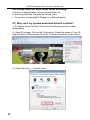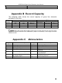
1
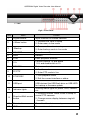
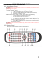
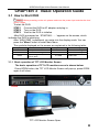
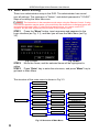
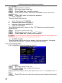
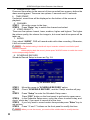
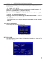
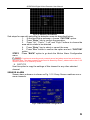
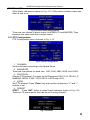
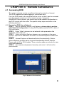
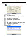
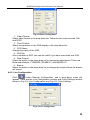
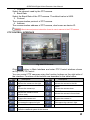
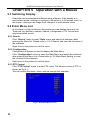
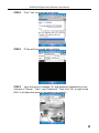
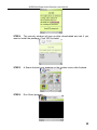
QSDF8204 Digital Video Recorder User Manual
QSDF8204
DVR User Manual
For H.264-4-channel Digital Video Recorder
All rights reserved
Rev 102208B
i
QSDF8204 Digital Video Recorder User Manual
CONTENTS
CHAPTER 1 Introduction ................................................................................. 4
1.1 DVR Introduction.......................................................................................... 4
1.2 Main Features and Functions....................................................................... 4
CHAPTER 2 Panel Functions .......................................................................... 6
2.1 Check Accessories....................................................................................... 6
2.2 Front Panel & Interface Terminals ................................................................ 6
2.3 Rear Panel ................................................................................................... 8
2.4 Remote Control Introduction ........................................................................ 9
2.4.1 Use Remote Control ................................................................................................... 9
2.4.2 Remote Control .......................................................................................................... 9
CHAPTER 3 Basic Operation Guide...............................................................11
3.1 How to Start DVR ........................................................................................11
3.2 Main Menu Setting ..................................................................................... 12
3.2.1 Basic Configuration .................................................................................................. 13
3.2.2 Live Configuration .................................................................................................... 14
3.2.3 Record Configuration ............................................................................................... 15
3.2.4 Alarm Configuration .................................................................................................. 17
3.2.5 PTZ Configuration .................................................................................................... 21
3.2.6 User Configuration ................................................................................................... 22
3.2.7 Network Configuration .............................................................................................. 24
3.2.8 Manager Tools.......................................................................................................... 26
3.3 Shortcut Menu............................................................................................ 29
3.3.1 PTZ .......................................................................................................................... 29
3.3.2 Search ..................................................................................................................... 30
3.3.3 Information ............................................................................................................... 34
3.3.4 Other........................................................................................................................ 34
CHAPTER 4 Remote Surveillance ................................................................. 35
4.1 Accessing DVR .......................................................................................... 35
4.1.1 Accessing DVR Over a Network ............................................................................... 35
4.1.2 Accessing DVR Over the Internet ............................................................................. 36
4.2 Main Interface ............................................................................................ 37
4.2.1 Login ........................................................................................................................ 37
4.2.2 Snap Picture ............................................................................................................ 37
4.2.3 Parameter Settings................................................................................................... 37
4.2.4 Record ..................................................................................................................... 38
4.2.5 Camera Audio .......................................................................................................... 38
4.2.6 DVR Status Panel..................................................................................................... 38
4.3 Remote Playback and Search.................................................................... 38
4.3.1 Remote Playback ..................................................................................................... 38
4.3.2 Other Functions........................................................................................................ 40
4.4 Remote DVR Configuration........................................................................ 42
4.4.1 Basic Configuration .................................................................................................. 42
4.4.2 Live Configuration .................................................................................................... 43
4.4.3 Record Configuration ............................................................................................... 44
4.4.4 Alarm Configuration .................................................................................................. 45
4.4.5 Network Configuration .............................................................................................. 45
4.4.6 User Configuration ................................................................................................... 45
4.4.7 Manage Tools ........................................................................................................... 45
4.5 Remote PTZ............................................................................................... 46
ii
QSDF8204 Digital Video Recorder User Manual
CHAPTER 5 Operation with Mouse ............................................................... 48
5.1 Switch Channel .......................................................................................... 48
5.2 Enter Menu List .......................................................................................... 48
5.2.1 Search ..................................................................................................................... 48
5.2.2 Configuration............................................................................................................ 48
5.2.3 PTZ Control.............................................................................................................. 48
5.2.4 Stop Record/Start Record ......................................................................................... 49
5.3 Fast Reverse and Fast Forward................................................................. 49
CHAPTER 6 Mobile Surveillance ................................................................... 50
6.1 By Smart Phone with WinCE Operating System ........................................ 50
6.2 By Smart Phone with Symbian Operating System ..................................... 52
CHAPTER 7 Frequently Asked Questions .................................................... 55
Appendix A Standard & Specifications ........................................................ 58
Appendix B Record Capacity ........................................................................ 59
Appendix C Abbreviation .............................................................................. 59
Q-See Product Warranty ……………………………………………………………..60
iii
QSDF8204 Digital Video Recorder User Manual
CHAPTER 1 Introduction
1.1 DVR Introduction
This DVR uses Dual Stream technology, and standard H.264 algorithm,
combined with a fashionable outline design and the latest advanced
video compression format, with a main processor that can process
recorded video and internet transmission simultaneously at different bit
rates and has a distinct independent LCD monitor embedded on the
front panel. This DVR has powerful internet functions including complete
remote control, good internet speed, and high-quality picture recording
with very low bit rate that saves HDD space to ensure the ability to
record for long periods.
1.2 Main Features and Functions
LIVE SURVEILLANCE
•
Supports channel security by hiding live display
•
Displays the local record status and basic information
•
Two level password control: administrator and common user
•
Supports USB mouse and remote control operation
•
7-inch TFT LCD pop-up screen monitor
COMPRESSION FORMAT
•
Standard H.264
RECORD MEDIA
•
Supports one SATA HDD to record
BACKUP
•
•
•
Supports backup via USB to USB flash memory
Supports backup remotely by network client
Two backup formats: DVR and AVI
RECORD & PLAYBACK
•
Recording modes: Manual operation, Sensor detection, Schedule
Record and Motion detection
•
Supports HDD recycling
•
Supports single channel playback
•
Supports four-channel playback on DVR
•
Supports deleting and locking recorded files
•
Supports remote playback in Network Client through LAN or
Internet
•
Two record search modes: time search and event search
ALARM
•
4
Four alarm inputs and one alarm output
QSDF8204 Digital Video Recorder User Manual
PTZ CONTROL
•
Supports various PTZ protocols
•
Supports 16 PTZ presets
•
Supports remote PTZ control
COMMUNICATION PORT FOR PTZ CAMERAS
•
RS 485 communication port
NETWORK
•
Supports TCP/IP protocol
•
Supports remote DVR configuration
•
Supports static IP, dynamic IP (DHCP) and PPPoE
•
Supports DDNS: Pending
•
Real-time live surveillance, remote playback and remote backup
•
Remote PTZ control and Preset setting
•
Supports IE browser
•
Supports Central Management software (short for CMS below) to
manage multiple devices over the Internet
•
Supports mobile viewing by phones and PDAs with WinCE or
Symbian operating systems on 3G networks
5
QSDF8204 Digital Video Recorder User Manual
CHAPTER 2 Panel Functions
Warning: Please power off the DVR before you connect other devices to it.
2.1 Check Accessories
When you receive the unit, please check the accessories and make sure
you have all of the parts.
Normally, accessories will include one mouse, a power cable, manual,
and some screws for installing HDD. If you purchased a complete
monitoring package, it will also include cameras, hard drive, Ethernet
cable, and cables, stands, and power adapters for the cameras.
2.2 Front Panel & Interface Terminals
The front panel layouts with the flip screen open and closed are shown
below. The functions of all buttons on the front panel are explained in the
following tables. The product you have may be slightly difference since
we sometimes upgrade or improve our products.
Item
1
2
3
4
5
6
6
Name
OPEN button
MENU
VOL +/CH +/CLOCK
HOUR/SET/MIN
Function
Pop-up or close the TFT LCD monitor screen
For adjusting the TFT monitor screen
Audio volume control
Change channels on TFT LCD monitor screen
Display time on TFT LCD monitor screen
Enter SETUP mode to correct the time display
QSDF8204 Digital Video Recorder User Manual
Fig2.1 Front Panel
Item
Name
Function
1
Digital buttons
Input numbers or choose cameras
2
+/Menu button
1. Increase the value in setup
2. Enter menu in live mode
3
-/Backup
1. Decrease the value in setup
2. Enter backup mode in live mode
4
RECORD
Record manually
5
REW
Rewind
6
PLAY
Enter playback interface
7
10+
Choose channel 10 and above
0-9, and double-click is 10.
8
SEARCH
Enter search mode
9
FF/PTZ
1. Fast forward
2. Enter PTZ mode in live
10
STOP/ESC
1. Quit playback mode
2. Exit the current interface or status
11
USB port
To connect USB mouse for control or external
USB devices like USB flash drive or USB HDD
for backup or firmware update
12
Indicator lights
Working status lights for power, HDD, network,
etc
13
Direction/Multi-screen
button
1. Direction buttons. Move cursor in setup or
control PTZ cameras
2. Change screen display between single &
4 screen
14
Enter button
To confirm the choice or setup
15
IR Receiver
For remote control
7
QSDF8204 Digital Video Recorder User Manual
2.3 Rear Panel
Layout subject to change, may be slightly different from your model.
The rear panel sketch and interface buttons are shown below:
Items
Functions
1
ALARM IN
Connect to external sensor 1-4.
2
ALARM OUT
Relay output. Connect to external alarm.
3
+5 V and GND
+5 Volt and ground connection
4
COM port
For debugging or data entry
5
RS485
Connection for PTZ cameras
6
RJ45 PORT
Connection for network or internet
7
Not Used
8
AUDIO IN
Audio input, connection for MIC or other audio
capture devices
9
AUDIO OUT
Audio output, connection for speaker
10
S-VIDEO
S-Video output, connect to monitor
11
VIDEO OUT
Connect to TV or monitor
12
VIDEO IN
POWER
INPUT
4ch Video inputs
13
8
Names
DC 12V
14
USB PORT
To connect USB mouse for control or external USB
devices like USB flash drive and USB HDD for
backup or firmware update
15
FAN
For cooling the device
QSDF8204 Digital Video Recorder User Manual
2.4 Remote Control Introduction
2.4.1 Using Remote Control
Notice: Please note that Remote Control is not a standard part of this DVR. Your
package might not include it.
To setup Remote Control:
1. Open the battery cover of Remote Control.
2. Put in two AAA batteries with poles aligned correctly.
3. Replace the battery cover.
If the Remote Control does not work, please check the following:
−
Are the batteries positioned correctly?
−
Do the batteries still have power?
−
Is something blocking the Infrared signal between the
Remote Control and the DVR?
−
Are signals transmitted by other devices interfering with
the Remote Control?
Notice: If none of the above problems apply, please contact Q-See to replace the
remote control.
2.4.2 Remote Control
The layout of the remote control is shown below.
9
QSDF8204 Digital Video Recorder User Manual
The functions of the buttons on the Remote Control are described in the
table below:
Items
1
Power Button
2
INFO Button
3
12
13
REC Button
Number and Letter
Buttons
Multi-Screen Button
SEARCH Button
MENU Button
ENTER Button
Direction Button
+/- Button
Playback Control
Button
AUDIO Button
Auto Dwell Button
14
A
15
PTZ Control Button
4
5
6
7
8
9
10
11
10
Names
Button
Functions
Start shutdown to stop firmware running. Do it
before powering off.
Get information about the DVR like firmware
version, HDD information
To record manually
Input numbers and letters or choose camera
To choose multi-screen display mode
To enter file search mode
To enter menu
To confirm the choice or setup
Move cursor in setup or move PTZ cameras
To increase or decrease the value in setup
To control playback, Fast
forward/rewind/stop/single frame play
To enable audio output in live mode
To enter auto dwell mode
Press the button to change input mode.
Including switches among capital letter, small
letters, numbers and special symbols
To control PTZ camera
Move camera/ZOOM/FOCUS/IRIS/SPEED
control
QSDF8204 Digital Video Recorder User Manual
CHAPTER 3 Basic Operation Guide
3.1 How to Start DVR
Notice: Before powering on the unit, please make sure the power input matches the local
power voltage.
To start the DVR:
STEP1 Connect the DVR to AC adaptor and plug in.
STEP2 Turn on the DVR.
STEP3 Wait for the DVR to initialize.
After DVR is powered on, ‘STARTING……’ appears on the screen, which
indicates the DVR is initializing.
After ‘WELCOME’ is displayed, you enter into live display mode. You can
press the "Menu" button to enter Main Menu.
The symbols displayed on the screen are explained in the following table:
Symbol
LIVE
A
DISK
Meaning
Live picture mode
Sensor recording
Percentage of hard
drive used
Symbol
REC
M
Meaning
Manual recording
Motion recording
V-LOSS
Video loss
3.1.1 Basic operation of TFT LCD Monitor Screen
The basic operation of TFT LCD monitor screen is shown below:
Press OPEN button, the TFT LCD Monitor Screen will pop-up, press OPEN
again it will close.
OPEN
TFT LCD Monitor Screen Open.
11
QSDF8204 Digital Video Recorder User Manual
3.2 Main Menu Setting
There is an administrator setup in the DVR. The administrator has control
over all settings. The username is "Admin", and default password is "123456".
Steps of entering the Main Menu are:
Notice: The instructions in the examples are the steps using the Remote Control. If using
a mouse the operation may be easier, you would follow the instructions in dialogue boxes and
navigate through menu items. If using the front panel buttons you cannot control PTZ
cameras, but the other operations are the same as the remote control.
STEP1 Press the "Menu" button, input username and password in the
Login interface (as Fig. 3.1), and then you will see the Main Menu (as Fig.
3.2).
Fig 3.2 Main
Fig 3.1 Login
STEP2 Move the cursor, and the selected items will be highlighted in
yellow
STEP3 Press "Enter" key to enter the sub-menu, and press "Menu" key to
get back to Main Menu
The structure of the main menu is shown in Fig 3.3.
BASIC CONFIG
LIVE CONFIG
RECORD CONFIG
MOTION ALARM
ALARM CONFIG
SENSOR ALARM
PTZ CONFIG
OTHER ALARM
USER CONFIG
BASIC CONFIG
NETWORK
IP CONFIG
SHUTDOWN SYSTEM
DISK MANAGEMENT
MENU
SYSTEM LOG
SYSTEM INFO
UPDATE FIRMWARE
DDNS CONFIG
MANAGER TOOLS
LOAD DEFAULT
CLEAR ALARM OUT
Fig 3.3 Structure of Main Menu
12
QSDF8204 Digital Video Recorder User Manual
3.2.1 Basic Configuration
Basic Configuration menu is shown as Fig. 3.4.
Fig 3.4 Basic Configuration
Fig 3.5 Time adjustment
1. VIDEO FORMAT
There are two video formats: NTSC and PAL. Please select according to your
area, NTSC is used in the USA.
2. TIME POSITION
This item is for setting up the position of the time on the display. There are
three options:
•
•
•
TOP: Time is displayed on top of the screen.
BOTTOM: Time is displayed at the bottom of the screen.
NO: Time is not displayed on the screen
3. Language
There are languages to be selected English or Spanish.
4. DVR NAME
Users can set DVR name with letters from ‘a’ to ‘z’ or numbers from ‘0’ to ‘9’.
STEP1 Press "A" button to switch the inputting mode from letters to
numbers
STEP2 Modify the DVR name.
STEP3 Press "Enter" key to confirm the operation.
13
QSDF8204 Digital Video Recorder User Manual
5. DVR ID
DVR ID consists of three numbers.
STEP1 Move the cursor to the item.
STEP2 Press "Enter" key to modify numbers.
STEP3 Enter three numbers, and then press "Enter" key to confirm the
modified entry.
STEP4 Press "OK" button to confirm the operation.
6. DATE FORMAT
There are three date formats:
•
•
•
Asian Date format: YY/MM/DD
European Date format: DD/MM/YY
American Date format: MM/DD/YY
7. TIME ADJUSTMENT
Time Adjustment menu is shown as Fig. 3.5. Please stop recording before
adjusting time.
STEP1 Move the cursor to the item.
STEP2 Modify numbers by using "+" and "-" buttons.
STEP3 Press "Enter" key to confirm the operation.
Notice: If you set a time that is before the current displayed time, the record between the
adjusted time and current time will be deleted automatically.
8. BUZZER ALARM
There are seven options to choose: always (continuous buzzer), 5 seconds,
10 seconds, 30 seconds, 1 minute, 2 minutes and 4 minutes.
3.2.2 Live Configuration
Live Configuration menu is shown in Fig. 3.6.
Fig 3.6 Live Configuration
1. CHANNEL
STEP1 Move the cursor to the item.
STEP2 Press "Enter" key to select the channel
2. CHANNEL NAME
User can set the channel name with letters from ‘a’ to ‘z’ or numbers from ‘0’
to ‘9’.
STEP1 Press "A" button to switch the inputting mode between letters and
numbers.
14
QSDF8204 Digital Video Recorder User Manual
STEP2 Enter channel name.
STEP3 Press "Enter" key to confirm the operation.
3. SHOW NAME
If selecting "SHOW NAME", the camera name will be displayed in live view. If
unselecting "SHOW NAME", the camera name will not be displayed.
4. CHANNEL HIDE
If selecting "HIDE", the video from the channel will not display in live view, but
it will still be recorded. If unselecting "HIDE", the video will be displayed.
5. CHANNEL COLOR
Change the values of contrast, brightness, saturation, and hue of the picture.
6. COPY CONFIG TO
Copy the configuration of one channel to any other selected channels. By
selecting “ALL”, users can copy the configuration to all other channels.
STEP1 Select the channel you want to copy this channel to, or select ALL
to copy the configuration to all other channels.
STEP2 Press "COPY" button.
STEP3 Press "Enter" key to confirm the operation.
3.2.3 Record Configuration
Record Configuration menu is shown in Fig. 3.7.
Fig 3.7 Record Configuration
1. VIDEO RESOLUTION
This unit supports CIF format.
Resolutions of different video formats are:
PAL: 352*288(CIF);
NTSC: 352*240(CIF)
2. RECYCLE
Checking the "RECYCLE" option means once the hard drive is filled the DVR
will continue to record by covering the previous recording automatically,
starting with the oldest. If you do not check "RECYCLE", recording will stop
once the hard drive is full.
15
QSDF8204 Digital Video Recorder User Manual
3. PRERECORD TIME
Prerecord time refers to the amount of time recorded from memory before the
alarm was triggered. There are two options: 5 seconds and 10 seconds.
4. TIME STAMP
If selected, record time will be displayed on the bottom of the screen at
playback
5. CHANNEL
STEP1 Move the cursor to the item.
STEP2 Press "Enter" key to switch the channel and select.
6. VIDEO QUALITY
There are five options: lowest, lower, medium, higher and highest. The higher
the picture quality, the clearer the image is, but more hard drive space will be
taken up.
7. AUDIO
If you check "AUDIO", DVR will record audio with video recording. Otherwise,
it will not record audio.
Notice: • The default setting is that Audio input1 matches channel1 and Audio input2
matches channel2.
• When playing back the record, please press "AUDIO" button to switch the sound
to the corresponding channel.
8. SCHEDULE RECORD
Schedule Record Setup is shown as Fig. 3.8.
Fig 3.8 Schedule Setup
STEP1
STEP2
up.
STEP3
Move the cursor to "SCHEDULE RECORD" option
Check "SCHEDULE RECORD", and the “Setup” window will pop
Press "Setup" to enter the Schedule Setup menu.
Press "ESC" button on the front panel to get back to upper menu.
STEP4 In the Schedule Setup menu, move the cursor to select a day, and
check “whole day” if you want to record all of the time.
STEP5 If you only want to record certain time periods press "Enter" key to
set up time.
STEP6 Press "+" and "-" buttons on the front panel to modify the time.
Notice: When you use the mouse, you need roll the middle wheel to modify the time.
16
QSDF8204 Digital Video Recorder User Manual
STEP7 Press "Enter" key to confirm the setup.
On weekday and holiday, you can select whole day or set four periods in a
day to record.
9. FRAME RATE SETUP
Frame rate is the number of pictures recorded each second. If choosing 15,
the picture-recording rate is 15 frames per second.
User can set frame rates based on the record mode.
If the video format is NTSC, there will be five frame rates to choose: 1, 3, 7,
15 and 30. The maximum frame rate is 30.
If the video format is PAL, there will be five frame rates to choose: 1, 3, 6, 12
and 25. The maximum frame rate is 25.
10. COPY TO
This option allows you to copy the settings of this channel to other selected
channels.
3.2.4 Alarm Configuration
Alarm Setup menu is shown as Fig. 3.9.
Fig 3.9 Alarm Configuration
MOTION ALARM
If you select Motion Alarm in Alarm Configuration, the submenu shown as Fig.
3.10 will be displayed.
Fig 3.10 Motion Alarm Configuration
17
QSDF8204 Digital Video Recorder User Manual
1. HOLD TIME
This sets the continued recording time after an alarm is triggered. There are
two options: 1 minute and 2 minutes. It also determines the interval between
motion detection events. If the HOLD TIME is 1 minute, if new motion is
detected within this period it will be considered part of the previous event
instead of the start of a new event.
2. CHANNEL
STEP1
Move the cursor to the channel.
STEP2 Press "Enter" key to switch the channel and select.
3. DETECTION
Checking "DETECTION" means to enable motion detection, not checking
means motion detection will not be enabled.
4. SENSITIVITY
This is the sensitivity level of the motion sensors.
The range is from ‘1’ to ‘8’. The higher the value, the more sensitive.
5. TO REC
If selecting "TO REC", DVR will record when motion is detected. If not, DVR
will not record when motion is detected.
6. ALARM OUT
There are two options: ALARMOUT1 and BUZZER.
•
When ALARMOUT1 is selected and an alarm is triggered, the DVR will
give send signal to the alarm out port.
•
When BUZZER is selected and the sensor is triggered, DVR will give a
buzzer alarm.
When the alarm output is unselected, DVR will not send an alarm.
7. SCHEDULE
This is the schedule for the motion detection. The default schedule is
everyday. Press "SETUP” button to set the motion detection schedule.
8. AREA
STEP1 Move the cursor to “setup”.
STEP2 Press "SETUP" button to enter the Area Setup submenu.
It displays the selected detection area (refer to Fig. 3.11). There
are four options:
−
ALL: motion anywhere in the area will be detected as shown
in the picture.
−
CUSTOM: You can select part of the area to be detected.
−
NULL: No area will not be open to motion detection
−
BACK: Go back to Motion Alarm Configuration menu.
18
QSDF8204 Digital Video Recorder User Manual
Fig 3.11 Detection Area Setup
Sub-steps for manually selecting the detection area are described below:
1. In the Area Setup submenu, choose "CUSTOM" option.
2. Press "Enter" key to confirm the operation.
3. Press "Up", "Down", "L eft" and "R ight" buttons to choose the
area which needs to be detected
4. Press "Enter" key to select or cancel the area.
5. Press "Esc" button to confirm the option and exit "CUSTOM"
option.
STEP3 Press "BACK" option to go back the Motion Alarm Configuration
menu.
Notice: If continuous recording mode, manual record and alarm record are activated at
the same time. The alarm events can be found in Search by Event”, please refer to the ‘3.3.2
Search’ function in ‘3 Search by Event’.
9. COPY TO
Use this option to copy the settings of this channel to any other selected
channel.
SENSOR ALARM
Sensor alarm submenu is shown as Fig. 3.12. Every Sensor matches one or
more channels.
Fig 3.12 Sensor Alarm Configuration
19
QSDF8204 Digital Video Recorder User Manual
1. HOLD TIME
This sets the continued recording time after an alarm is triggered. There are
two options: 1 minute and 2 minutes. It also determines the interval between
motion detection events. If the HOLD TIME is 1 minute, if new motion is
detected within this period it will be considered part of the previous event
instead of the start of a new event.
2. SENSOR
STEP1 Move the cursor to the "SENSOR" option.
STEP2 Press "Enter" key to switch the Sensor.
3. DETECTION
This is the switch of the sensor alarm. If you check "DETECTION", DVR will
begin detecting. If you do not check it, the detection function is disabled.
4. TYPE
Press "Enter" key to enter the sub-menu. There are two options: NO and NC.
‘NO’ means normal open. If ‘NO’ is chosen, the DVR will be triggered when
the alarm when the voltage drops.
‘NC’ means normal close. If ‘NC’ is chosen, the DVR will be triggered when
the alarm sends a high voltage charge.
5. TRIGGER RECORD
One channel can connect with one sensor. However, one sensor can trigger
one or more channels.
STEP1 Move the cursor to "TRIGGER RECORD" option.
STEP2 Select the channel you want that sensor to trigger.
STEP3 Press "Enter" key to confirm the operation.
For example, if you select the sensor named SENSOR1 and the trigger
records named CAM1 and CAM2, it will record on channel 1 and channel 2
when the SENSOR1 is triggered.
6. ALARM OUT
There are two options: ALARMOUT1 and BUZZER.
•
When ALARMOUT1 is selected and the sensor is triggered, DVR will
give send a signal to the alarm out port.
•
When BUZZER is selected and the sensor is triggered, DVR will give
buzzer alarm.
•
When the alarm output is unselected, DVR will not send alarm.
7. SCHEDULE
This is the schedule of when the sensor detection is active. The default
schedule is everyday.
8. COPY TO
Users can copy the setting of this channel to all or any other selected
channel.
20
QSDF8204 Digital Video Recorder User Manual
OTHER ALARM
Other Alarm submenu is shown in Fig. 3.13. Other alarm includes video loss,
disk full and so on.
Fig 3.13 Other Alarm Configuration
There are two options of alarm output: ALARMOUT1 and BUZZER. Their
functions are same with that in sensor alarm.
3.2.5 PTZ Configuration
PTZ Configuration menu is shown in Fig. 3.14.
Fig 3.14 PTZ Configuration
1. CHANNEL
Set the channel connecting to the Speed Dome.
2. BAUDRATE
There are five options for baud rate: 1200, 2400, 4800, 9600, and 19200.
3. PROTOCOL
Choose PTZ protocol. Currently the DVR supports PELCO_D, PELCO_P,
MINKING, NEON, STAR, VIDO, DSCP, VISCA and LILIN.
4. ADDR
Set PTZ address. Press "Enter" key and use the number key, "+" and "-"
buttons to set.
5. PRESET
STEP1 Press "SET" button to enter Preset submenu shown in Fig. 3.15.
There are 16 preset points that can be set in every channel.
Fig 3.15 Preset
21
QSDF8204 Digital Video Recorder User Manual
STEP2 In Preset submenu, press "Enter" button to switch the preset point
needing to be reset.
STEP3 Press "ADJUST" button to enter PTZ mode.
STEP4 On the front panel, press "ZOOM", "FOCUS", "SPEED", "IRIS", "+"
(MENU) and "-" (PTZ) buttons to modify the position of the preset point.
STEP5 Press "UP", "DOWN", "RIGHT" and "LEFT" buttons to rotate the
Speed Dome.
STEP6 Press "ESC" button to come back to Preset menu.
STEP7 Press "SAVE" button to save the setting, and press "CANCEL" to
discard the setting.
Notice: how to use the presetting point:
Users can use the number keys to switch the preset point in PTZ mode. First
press "PTZ" button to enter PTZ mode, then press the number key such as "1", and the
Speed Dome will move to preset point 1.
6. COPY TO
You can use this option to copy the settings of this channel to all channels or
any other selected channel.
3.2.6 User Configuration
User Configuration is shown as Fig 3.16. The default username is Admin.
Administrator can add users, set users’ authorization and delete users.
Fig 3.16 User Configuration
22
QSDF8204 Digital Video Recorder User Manual
Fig 3.17 Authority Setup
1. AUTHORIZATION CHECK
If you put a checkmark in "AUTHORIZATION CHECK", all users need to input
the password before entering the Main Menu.
If you do not check "AUTHORIZATION CHECK", users can enter the system
directly without password.
2. USER
Press "Enter" key to switch to another user. Use "+” and "-" buttons change
users.
3. PASSWORD
The default password of administrator is ‘123456’. Users can change
password that is made up of numbers from 0 to 9.
4. AUTHORIZATION
STEP1 Move the cursor to "User" option, then press "Enter" key to switch
to the user whose authorization you want to modify.
STEP2 Move the cursor to "SETUP" button on the screen.
STEP3 Press "Enter" key, Authority Setup menu (refer to Fig. 3.17) will
pop up.
STEP4 In the Authority Setup menu, move the cursor to "DEFAULT".
STEP5 Press "Enter" key. The default authorization will be set.
The default authorizations include:
−
Live preview, playback, backup, and Record in local system
−
Live preview, playback, backup, and Record in remote
network client
5. NEW USER
STEP1 Move the cursor to "ADD" button on the screen.
STEP2 Press "Enter" key, the Add User menu will display.
STEP3 Input username and password.
STEP4 Press "OK" button to confirm the option.
Username is formed by numbers or letters with a maximum of 15 characters.
The Password is numbers between 0 and 9.
23
QSDF8204 Digital Video Recorder User Manual
6. DELETE USER
STEP1 Move the cursor to the "DEL" button on the screen.
STEP2 Press "Enter" key to confirm the operation. When a user is deleted,
the username and password will no longer exist in the system.
3.2.7 Network Configuration
Network Configuration menu is shown as Fig. 3.18.
Fig 3.18 Network Configuration
Fig 3.19 Basic Configuration
BASIC CONFIGURATION
Basic Configuration submenu is shown as Fig. 3.19.
STEP1 Move the cursor to “Basic configuration”.
STEP2 Press "Enter" key to enter the Basic Configuration menu.
1. NET SERVER
If you select the check box and set the port number of the server, you will
enable the NET SERVER.
2. NET VIDEO QUALITY
This refers to the picture quality in remote surveillance. There are three
options: low, medium and high. The higher of the quality value, the clearer the
image is, the lower the quality value, the less bandwidth the video takes up.
The default level is medium.
IP CONFIGURATION
IP Configuration submenu is shown as Fig. 3.20.
Fig 3.20 IP Configuration
24
QSDF8204 Digital Video Recorder User Manual
Fig 3.21 System Information
This is the DVR’s IP configuration. There are three options: STATIC, DHCP
and PPPoE.
If you use the Static IP address option you will need to access the router the
DVR is attached and get the setup information. You can do this by going to
the run option on a computer that is attached to the same router as the DVR
and typing cmd or command to get to a command prompt. At the command
prompt type ipconfig and hit ENTER to access the network information. The
screen will list the computer’s IP address, the Subnet Mask, and the Gateway.
The IP address you assign to the DVR must have the same first 3 sets of
numbers as the Gateway. If the computer’s IP address ends in a 1 or 2-digit
number, you can select an IP address ending in 100, if the computer’s IP
address ends in a number in the 100s then select an IP address ending in
200.
STEP1 Input IP Address, Subnet Mask and Gateway
STEP2 Press "OK" button to modify the IP Configuration menu.
If you select DHCP, the router will automatically assign the IP address. After
selecting DHCP, you need to wait about 30 seconds. The automatically
assigned IP will be displayed in the system information window.
If you are attaching the DVR directly to a DSL or cable modem/router, you can
use the PPPoE option. You need to input username and password when
connecting to internet. You would get the username and password
information from your internet service provider.
If you press the "INFO" button, System Information menu can be displayed on
the screen as long as the DVR connects with the network well (refer to Fig.
3.21).
Notice: • If the local area network has a DHCP server or the router the DVR is attached to
supports DHCP we recommend using the DHCP option.
• Before you set PPPoE, you need to reboot the modem. After setting the PPPoE,
you need wait for a while for the settings to take effect.
25
QSDF8204 Digital Video Recorder User Manual
DDNS CONFIGURATION
DDNS Configuration submenu is shown as Fig. 3.22. The DVR does not
currently support any DDNS servers in the USA, support may be added in
future firmware updates.
Fig 3.22 DDNS Configuration
3.2.8 Manager Tools
The Manager Tools menu is shown as Fig. 3.27.
Fig 3.27 Manager Tools
SHUTDOWN SYSTEM
This option is used to shut down the system.
STEP1 Enter the SHUTDOWN submenu.
The following words will be shown: ‘Are you sure to shut down
DVR system?’.
STEP2 Press "Enter" key to confirm the operation.
Fig3.28 Disk Management
DISK MANAGER
Disk Manager Submenu is shown as Fig. 3.28.
Fig 3.28 Disk Manager
26
QSDF8204 Digital Video Recorder User Manual
There are two options: FORMAT and CANCEL.
1. QUICK FORMAT
If you check this item, you can format the hard drive quickly.
2. FORMAT
STEP1 Select "FORMAT" button.
STEP2 Press "Enter" key, a warning will pop up: ‘Format will erase all data
on this hdd! Format now? ’
STEP3 Press "OK" button to format the HDD; Press "CANCEL" or "ESC"
button to cancel this operation.
Notice: • When a hard drive is used for the first time the system will remind you to format
the HDD when the DVR is started up. HDD cannot record until it is formatted.
• Before you can format the HHD you must stop recording and playing back.
• Time it takes to format the HDD depends on the HDD capacity. The higher the
capacity is, the longer it takes. Normally, a 40G HDD takes about eight seconds to format.
SYSTEM LOG
System log submenu is shown as Fig. 3.29.
The DVR will note all operations, status, and time automatically while working.
You can view them through searching using the Log Search.
Fig 3.29 Log Search
1. LOCAL, NET, AND OTHER
Check the corresponding items of local operation, network client operation
and other operation first. (Note: VLOSS is video loss)
2. TIME
Select start time and end time of the log file you want to view.
Press "OK" button to view the event log; Press "CANCEL" or "ESC" button to
cancel this operation.
The information in log files contains start time, end time and log file types. For
example, 110707:092151 means 2007-7-11 9:21:51 and N-L means the
LOGIN of the NET.
If there are too many log lists, you can use "PREV" button to page up and
"NEXT" button to page down.
27
QSDF8204 Digital Video Recorder User Manual
SYSTEM INFORMATION
System information submenu is shown as Fig. 3.30. It displays the
information about the system, such as firmware version, device name, DVR
IP ADDRESS, Client information and so on.
Fig 3.30 System Information
Press the "INFO" button on the front panel and it will display the system
information on the screen.
UPDATE FIRMWARE
Fig 3.31 Update Firmware
Update Firmware submenu is shown as Fig. 3.31. Users can use USB flash
drive to update the firmware.
Steps are described below:
STEP1 Make sure the firmware update is on the USB flash drive.
STEP2 Enter the menu after word-‘USB’ is displayed on the live mode.
STEP3 Move the cursor to "UPDATE" button.
STEP4 Press "Enter" key to start updating.
STEP5 After the program is upgraded, the system will restart.
LOAD DEFAULT
Fig 3.33 Load Default
Load Default menu is shown as Fig. 3.33. Click YES, and it will recover the
default setting installed at the factory.
28
QSDF8204 Digital Video Recorder User Manual
IMPORT CONFIGURATION & EXPORT CONFIGURATION
This function is used to help users manage multiple DVRs conveniently.
When users need to set up the same parameters in more than one DVR, they
can copy one DVR’s setting to all others without setting them up one by one.
EXPORT CONFIGURATION can copy one DVR’s parameter settings to a
USB flash drive; and then use IMPORT CONFIGURATION to input the
settings copied onto the USB flash drive from the first DVR to another DVR.
CLEAR ALARM OUT
This item is to clear the current alarm out, please refer to Fig. 3.34.
Fig 3.34 Clear Alarm Out
3.3 Shortcut Menu
3.3.1 PTZ
Fig 3.35 PTZ Mode
PTZ mode is shown as Fig. 3.35. To switch the channel to which the video
output of the Speed Dome connects you press "PTZ" button to enter the PTZ
mode.
In the live view of PTZ mode the default channel is channel 1, you can use
mouse to change the channel number to enter the corresponding channel
PTZ mode.
SPEED
STEP1 In PTZ mode, press "Speed" button.
STEP2 Press "+" and "-" buttons to change the rotational speed.
STEP3 Press "Up", "Down", "Left" and "Right" buttons to rotate the Speed
Dome to a certain position.
29
QSDF8204 Digital Video Recorder User Manual
ZOOM
STEP4
STEP5
In PTZ mode, press "ZOOM" button.
Press "+" and "-" buttons to zoom in and zoom out.
FOCUS
STEP1
STEP2
In PTZ mode, press "FOCUS" button.
Press "+" and "-" buttons to control focus.
IRIS
STEP1
STEP2
Dome.
In PTZ mode, press "IRIS" button.
Press "+" and "-" buttons to change the brightness of the Speed
3.3.2 Search
Press the "Search" button, there are five submenus displayed on the screen:
PLAYBACK, BACKUP, DELETE and LOCK. Data menu is shown as Fig.
3.36.
Fig 3.36 Data Menu
PLAYBACK
1. Select the Date
STEP1 In Playback menu, move the cursor to Calendar
STEP2 Press "Enter" key to enter the Calendar submenu.
Calendar submenu is shown as Fig. 3.37.
Fig 3.37 Calendar
Notice: You can search for records by time search or event search. The times displayed
in red have record files.
30
QSDF8204 Digital Video Recorder User Manual
2. Search by Time
All records can be searched through this option. Steps of searching by time
are below:
STEP1 In Calendar submenu, select date.
STEP2 Press "Enter" key to enter the Playback submenu, refer to Fig.
3.38.
STEP3 Press "Enter" key to select channels.
STEP4 Select time of the day
The times in red have record files. The first line is hour, and the
second line is minute.
STEP5 Select "PLAY" button.
STEP6 Press "Enter" key to play the record.
Notice: • the DVR supports playing back in full screen mode and quad screen mode.
- When you play back the record in full screen mode, you may use the number
buttons or "Up", "Down", "Left" and "Right" buttons to switch the channel.
- When you play back the record in quad screen mode, you can only see the
record playing back as normal speed.
• When you play back the record, you may press "INFO" button on the front panel
to play or stop channel audio.
Fig 3.38 Playback
3. Search by Event
Steps for searching by event are below:
STEP1 In Playback submenu, select the camera and date. The dates
having recorded events are highlighted in red.
STEP2 Move the cursor to event option.
The Event search types are: MOTION and SENSOR
STEP3 Press the "Down" button to move the cursor to "EVENTS" button in
the submenu.
STEP4 Press "Enter" key to enter the event list.
STEP5 Vies the list information.
Taking one of the event records information as an example the
meanings of the words are described below:
−
CH: Channel
−
START TIME: The start time of the record.
−
TYPE: The type of the event. There are two types of event:
MOTION and SENSOR.
−
M: Motion detection
−
A: Sensor detection
−
LOCK: Lock status of files.
31
QSDF8204 Digital Video Recorder User Manual
STEP6
STEP7
STEP8
Choose an event record.
Press "Enter" key to play back the record
Press "Stop" button to get back to live display mode.
Notice: If event list is over one page, use "PREV" and "NEXT" buttons to view next page.
BACKUP & VIEW BACKUP
1. BACKUP
Select the Backup submenu in the Data menu to enter the Backup submenu
shown as Fig. 3.39.
Fig 3.39 Backup
(1) BACKUP MEDIA
Backup media refers to the device you are copying the record to. There are
five options: DVD-R, DVD-RW, DVD+R, DVD+RW and USB disk. They
connect with DVR through USB interface.
(2) BACKUP FILE
It denotes the format of backup files. This system supports AVI and DAT video
formats.
•
When selecting the format that DVR supports, the video format of
backup files is DAT.
•
Before playing the record of AVI format, it is necessary to install the
decoder at first.
(3) START TIME
It is start time of recording at backup. The first line is hour, and the second line
is minute. Users should choose the date firstly and choose the time secondly.
(4) END TIME
It is end time of recording at backup. The first line is hour, and the second line
is minute. Users should choose the date firstly and choose the time secondly.
(5) CHANNEL
It supports to select more than one channel at the same time.
(6) EVENTS
There are two options: motion and sensor. If you want to backup all records,
please select "ALL".
32
QSDF8204 Digital Video Recorder User Manual
(7) BACKUP
Before to backup, users should select BACKUP MEDIA, BACKUP FILE,
CHANNEL, START TIME, END TIME and EVENTS.
STEP1 Press "BACKUP" button, the backup information of DVR will
display on the screen (refer to Fig. 3.40).
Fig 3.40 Backup Information
STEP2
Press "START" button, and backup will start.
The progress of backup will be displayed on the screen. If stopping
recording at backup, its speed will be faster.
STEP3 When the backup is over, the system will pop up a dialog box
saying ‘BACKUP COMPLETELY’.
2. VIEW BACKUP
If backing up with AVI format, most media players can play directly as long as
to install a decoder in advance. Installation method: Enter "Decode" file (being
created automatically by system at your backup.), then double-click
"InstallDecode.bat" file to Install successfully.
If backing up with the format DVR supports, the file player will be copied
automatically in the file copying media.
DELETE
Delete submenu is shown as Fig. 3.42. The operation is shown below:
Fig 3.42 Delete
STEP1 Press "Enter" key to enter the Delete submenu.
STEP2 Press "Enter" key to select the record.
STEP3 Move the cursor to "DELETE" button and press "Enter" key,
information will be given as below:
‘SOME RECORDS WILL BE DELETED, CONTINUE?’
STEP4 Select "OK" button.
STEP5 Press "Enter" key to delete this record.
33
QSDF8204 Digital Video Recorder User Manual
LOCK/UNLOCK
Lock submenu is shown as Fig. 3.43. Its function is to lock or unlock the
record.
Fig 3.43 LOCK/UNLOCK
Use "Enter" key to change the state. If a record event is locked, it cannot be
deleted or covered.
3.3.3 Information
Press "INFO" button, and the information will appear on the screen, such as
HDD quantity, usable rate of HDD, record mode including
manual/alarm/motion, etc.
3.3.4 Other
•
In live display mode, if pressing "Up" button, it will display the first
channel in full screen.
•
If pressing "Down" button, it will display the second channel in full
screen.
•
If pressing "Left" button, it will display the third channel in full screen.
•
If pressing "Right" button, it will display the fourth channel in full screen.
•
If pressing "Enter" button, it will display the four-divided channel.
•
If pressing "Audio" button, it will switch the voice of corresponding
channel in live display mode.
34
QSDF8204 Digital Video Recorder User Manual
CHAPTER 4 Remote Surveillance
4.1 Accessing DVR
The system supports remote surveillance through a network or Internet.
This DVR supports five users logging in at the same time.
First, the DVR needs to be connected with a router so that it can be accessed
over the network or Internet. As for network access, it supports
Win2000/XP/Vista. Second, you need to set up the network configuration in
the DVR to work with the router. The specific setup steps are shown in the
following sections.
4.1.1 Accessing DVR Over a Network
STEP1 Input IP address, Subnet, and Gateway, please refer to section
3.2.7 Network Configuration. If using DHCP, please enable DHCP in both of
DVR and router.
STEP2 Enter “Video” submenu to set network video parameters like
resolution, frame rate, etc.
STEP3 Open an Internet Explorer browser on a computer on the same
network. Input the IP address of the DVR in an Internet Explorer textbox and
hit enter.
STEP4 Internet Explorer will download ActiveX automatically. (Notice:
Internet Explorer must be set up to permit downloading ActiveX controls.
Please refer to Q7 in FAQ chapter) Then a window pops up and asks for user
name and password.
STEP5 Input name and password correctly, and enter. It will show the
picture below:
Fig 4.1 Network Client Interface
35
QSDF8204 Digital Video Recorder User Manual
4.1.2 Accessing DVR Over the Internet
When accessing the DVR over the Internet, in addition to the above steps, you
would then need to forward port 80 on the router the DVR is attached to, to the IP
address of the DVR. You can get instructions on how to do this for most popular
routers by going to the www.portforward.com website. On this website click on the
orange “Routers” link in the second paragraph (RED box in Fig 4.1.1), which will
open a list of router manufactures, then find the brand and model of your router on
the list and click on the link. On the next page that opens click on the orange
“Default Guide” link (BLUE box in Fig 4.1.2), this will take you to the port forwarding
instructions for your router.
Fig 4.1.1
Fig 4.1.2
When you access the DVR from a remote computer, you also need to use a
different address in the Internet Explorer browser window. Instead of entering
the IP address of the DVR you need to enter the public IP address of the
router the DVR is attached to. You can get this address by going to
www.myipaddress.com from a computer that is attached to the same router
as the DVR. This website will display the box in Fig 4.1.3 below that shows
the IP address you need to use. It will be in the space where the below
example shows 76.254.183.54.
36
QSDF8204 Digital Video Recorder User Manual
Fig 4.1.3
4.2 Main Interface
The function buttons of the remote surveillance display are shown in Fig.4.4.
Login
Software Setup
Remote Playback
Remote DVR Configuration
Remote PTZ
Large Picture
Quad Picture
Next Video Channel
Camera Audio
Snap Picture
DVR Record
Fig 4.4 Main Interface
4.2.1 Login
The operation of the network client is the same as the DVR. Default
username is ‘Admin’ and password ‘123456’.
STEP1
window
STEP2
Click
button to input username and password in the login
Press "Enter" key to login.
Notice: Click "EXIT" button to exit the system
4.2.2 Snap Picture
Take live picture. Press
to take the picture.
4.2.3 Parameter Settings
In Parameter Settings window, the number of pictures taken at once can be
set. If selecting five, it can take five pictures every time you click "Snap
Picture" button.
37
QSDF8204 Digital Video Recorder User Manual
4.2.4 Record
STEP1 Click "DVR Record" button.
STEP2 Select "Start Record" in drop down list to record.
STEP3 Select "Stop Record" in drop down list to stop recording.
4.2.5 Camera Audio (for cameras that have microphones)
There are two options: close camera audio and open camera audio. The
setting steps are:
STEP1 When you are in live display mode or playback mode, select a
channel to display in Large Picture mode.
STEP2 Right-click the image and then select "Open Audio" to play the
camera’s audio.
STEP3
Click
button to turn the audio up or down.
4.2.6 DVR Status Panel
Meanings of the colored indicator lights in the main interface are shown
below:
1.
Grey light: Normal State
2.
Green light: Manual Record State
3.
Yellow light: Motion Detection Record State
4.
Red light: Sensor Alarm Record State
5.
Blue light: Video Loss State
4.3 Remote Playback and Search
4.3.1 Remote Playback
Click
button on Main Interface to enter playback mode, which is shown
as Fig 4.5 Remote Playback.
Search By Date
Search By Channel
Backup
Lock
Record Playback and Control
Snap Picture
Event Search
Fig 4.5 Remote Playback
38
QSDF8204 Digital Video Recorder User Manual
Meanings of the function buttons in Remote Playback window are shown
below:
1.
: Play /Pause.
2.
: Stop.
: Next frame. This button will be valid when playback is paused.
3.
4. You can adjust the speed for playing record in the area shown as Fig 4.6
Speed.
Fig 4.6 Playing Speed
Bar
Fig 4.7 Data Preview
Fig 4.7 Data Preview shows with channels have recorded at data at different
times. In the figure, left side shows the available channels. When a certain
channel has been selected for playback, its background color will be
highlighted and ‘ ’ sign will appear beside the channel title.
The center area of data preview gives details of the record files. Different
colors of the bar show different types of records. The following are the
definitions of the color bars:
Blue: Manual Record Events
Green: Schedule Record Events
Yellow: Motion Detection Record Events
Red: Sensor Alarm Record Events
The ruler on top of the bar shows the 24 hours in a day. Right-click the ruler, it
will be magnified 10 multiples, so that users can select accurate time.
When searching for a certain section of a record, please draw the bar to the
right position. If necessary, right-click the bar to see the magnified time marks
to search more precisely.
button to play the selected record.
STEP1 Click
When returning to live display mode after finishing remote playback, it will
display ‘connect…’on the screen, and you may click "Large Picture" or
"Quad Picture" button to refresh the screen to get a live picture.
39
QSDF8204 Digital Video Recorder User Manual
4.3.2 Other Functions
BACKUP
Click
button to enter the Backup window shown as Fig 4.8 Backup.
Fig 4.8 Backup
There are two methods of backup: by time and by event.
1. TIME BACKUP
STEP1 Select time and record type.
STEP2 Select camera.
STEP3 Press "Browse…" button to select the folder with saved backup
files.
STEP4 Select cameras that you want to backup.
STEP5 Select the type of backup file.
STEP6 Click "Backup Now" button, backup will begin.
2. EVENT BACKUP
STEP1 Select time and record type.
STEP2 Select camera.
STEP3 Press "Browse…" button to select the folder with saved backup
files.
STEP4 Select cameras that you want to backup.
STEP5 Select the type of backup file.
STEP6 Click "Select Event" button to enter Select Event window shown
as Fig 4.9 Select Event.
Fig 4.9 Select Event
40
QSDF8204 Digital Video Recorder User Manual
STEP7
1. Choose event and press ">>" button to go to backup list,
Click ">>>>" to choose all events.
2. Choose event list and press"<<" button to clear selected
event; click "<<<<" button to clear all events.
Click "OK" button to run the backup.
LOCK /UNLOCK
You can use this option to select to lock or unlock files.
STEP1 Click
Remote Lock.
button to enter Remote Lock window as Fig 4.10
Fig 4.10 Remote Lock
Fig 4.11 Lock Event
STEP2 Select time and record type.
STEP3 Select camera.
STEP4 Click "Select Event" button, system will find the corresponding
event and pop up the LOCK EVENT window shown as Fig 4.11 Lock Event.
STEP5 Check the check box to change lock status.
Lock Status shows ‘√’ indicating that the event is locked, otherwise
it means unlocked.
STEP6 Click "OK" button to confirm the operation.
41
QSDF8204 Digital Video Recorder User Manual
4.4 Remote DVR Configuration
Click
button in Main Interface to enter the DVR Configuration interface
shown as Fig 4.12 Remote DVR Configuration.
Fig 4.12 Remote DVR Configuration
Definitions of buttons in Fig 4.12 are below:
System Configuration
Live configuration
Record Configuration
Alarm Configuration
PTZ Configuration
User Configuration
Management Tools
Return
Through the Remote Configuration interface, users can set all configurations
remotely. Its operation is the same as that in the DVR.
4.4.1 Basic Configuration
button in Remote Configuration and enter Basic Configuration
Click
shown as below Fig 4.13 Basic Configuration.
After changing settings, click the "OK" button, the settings will be saved and
enabled on the DVR.
42
QSDF8204 Digital Video Recorder User Manual
Fig 4.13 Basic Configuration
1. Video Format
Select video format in the drop down list. There are two video formats: PAL
and NTSC.
2. Time Position
Select time position on the DVR display in the drop down list.
3. DVR Name
Change the name of the DVR.
4. DVR No.
Give a number to DVR, this can be useful if you have more then one DVR.
5. Date Format
Select the option in the drop down list to change the date format. There are
three date formats: YY/MM/DD, DD/MM/YY, and MM/DD/YY.
6. Buzzer
Select the option in the drop down list to change the length of time the buzzer
will sound.
4.4.2 Live Configuration
button Remote Configuration, and a drop down menu will
Click
appear. There are the Live Configuration window and Color Settings window
shown in Fig 4.14 Live Configuration and Fig 4.15 Color Settings.
Fig 4.14 Live Configuration
43
QSDF8204 Digital Video Recorder User Manual
Fig 4.15 Color Settings
LIVE CONFIGURATION
1. Channel
Select the option in the drop down list to change the channel of the camera.
2. Channel Hide
Select the check box to hide the picture in the live display mode.
3. Show Name
Select the check box to hide the name of DVR channel in the live display
mode.
4. Channel Name
Change the name of the channel.
COLOR SETTINGS
1. Channel
Select the option in the drop down list to change the channel of DVR.
2. Brightness /Contrast /Saturation /Hue
Adjust the brightness, contrast, saturation, and hue for every channel by
moving the slider.
4.4.3 Record Configuration
Record Configuration window is shown as Fig 4.16 Record Configuration.
Fig 4.16 Record Configuration
44
QSDF8204 Digital Video Recorder User Manual
1. Parameter Setting
This setting is the same as ‘3.2.3 Record Configuration’ of the DVR. If you
change it on Network Client, the DVR will change along with it.
2. Schedule Record
The default value of Schedule Record is not active.
STEP1 Click the check box of the Schedule Record, and it will be active.
The default schedule time is every day.
STEP2 Click "Set Schedule" button, and Schedule Configuration window
will pop up as Fig 4.17 Schedule Configuration.
Eraser
Add
Fig 4.17 Schedule Configuration
STEP3 Click "Eraser" button and click on the weekday schedule to delete
the time; Click "Add" button and click on the weekday schedule to add the
time.
4.4.4 Alarm Configuration
button in Remote Configuration, and a drop down menu will
Click
appear. There is the Motion Alarm window, Sensor Alarm window and Other
Alarm window. The setting is the same as ‘3.2.4 Alarm Configuration’ of the
DVR. If you change it here, the DVR will change along with it.
4.4.5 Network Configuration
Click
button to change the video quality of Network Client.
4.4.6 User Configuration
The setting of User Configuration window is the same as ‘3.2.6 User
Configuration’ of the DVR. The added users in one server can login to the
Server and Client.
4.4.7 Management Tools
button in Remote Configuration, and a drop down menu will
Click
appear. There is the Disk Management window, Software Update window,
Load Default window, System Information window and System Log window.
45
QSDF8204 Digital Video Recorder User Manual
DISK MANAGEMENT
Displays the information of the hard disk.
FIRMWARE UPDATE
DVR firmware can be updated remotely through Network Client software.
STEP1 Select the path to the updating file.
STEP2 Click "Start" button, the updating progress bar will appear. The
Update dialog box is shown as Fig 4.18 Firmware Update.
Fig 4.18 Firmware Update
STEP3 After finishing the update, the DVR needs to reboot to run the new
firmware.
LOAD DEFAULT
Load default setup.
SYSTEM INFORMATION
This displays the information of the DVR, such as firmware version, DVR
name, MAC address and so on.
SYSTEM LOG
This displays the information about operating information on the DVR.
4.5 Remote PTZ
PARAMETERS
Before operating Remote PTZ, you need to set the PTZ configuration. The
PTZ Configuration window is shown as Fig 4.19 PTZ Configuration.
Fig 4.19 PTZ Configuration
46
QSDF8204 Digital Video Recorder User Manual
1. Channel
Select the channel used by the PTZ camera.
2. Baud Rate
Select the Baud Rate of the PTZ camera. The default value is 9600.
3. Protocol
The communication protocol of PTZ camera.
4. Address
The communication address of PTZ camera, also known as device ID
Notice: Baud rate and protocol should be found in user’s manual of the PTZ camera
PTZ CONTROL INTERFACE
Fig 4.20 PTZ Control
Click
button in Main Interface and enter PTZ Control interface shown
as Fig 4.20 PTZ Control.
You can control PTZ cameras using the function buttons on the right side of
the interface. Functions of the buttons are described in the table below:
Icon
Description
Icon
Description
Right
Moves the camera to the right
Left
Moves the camera to the left.
Up
Moves the camera up
Down
Moves the camera down
FOCUS+
Moves the camera’s focus
further away
ZOOM+
Zooms the camera out
IRIS+
Increases the camera’s light.
Go to a Preset Point
FOCUSMoves the camera’s focus closer
ZOOMZooms the camera in.
IRISDecreases the camera’s light.
Set a Preset Point
Adjust PTZ speed
Sets the rotational speed of the camera
47
QSDF8204 Digital Video Recorder User Manual
CHAPTER 5 Operation with a Mouse
5.1 Switching Display
Channels can be selected and altered using a Mouse. If the display is in
multi-screen mode, clicking on a picture it will switch it to full screen; and if in
full screen, clicking on an image it will change it to multi-screen mode.
5.2 Enter Menu List
In live mode, by right clicking on the picture you can display the menu list.
There are four menus to choose: Search, Configuration, PTZ Control and
stop record/start record.
5.2.1 Search
Click "Search" menu to enter “Data” menu and select the submenu after
entering the Menu list. Please refer to ‘3.3.2 Search’ and view the functions of
the submenu.
Right click on the picture to exit the menu.
5.2.2 Configuration
Configuration submenu is used to display the Main Menu
Click "Configuration" menu to enter the Main Menu and select the submenu
after entering the Menu List. Please refer to ‘3.2 Main Menu Setting’ to view
the function of the submenu.
Right click on the picture to exit the menu.
5.2.3 PTZ Control
Click "PTZ Control" menu to enter PTZ mode. The shortcut menu of PTZ is
shown as Fig 5.1
You can control the focus, zoom, and iris through this interface.
Fig 5.1 Shortcut Menu of PTZ
48
QSDF8204 Digital Video Recorder User Manual
FOCUS
Click "FOCUS+" button to focus the Speed Dome further away. Click
"FOCUS-" button to focus the Speed Dome closer.
ZOOM
Click "ZOOM+" and "ZOOM-" buttons to control the Speed Dome zooming in
and zooming out.
IRIS
Click "IRIS+" and "IRIS-" buttons to increase and decrease the light in the
image in the Speed Dome.
Notice:
, ,
right, left and down.
and
buttons are used to control the Speed Dome to move up,
5.2.4 Stop Record/Start Record
This menu is for starting and stopping recording.
Stop record
Click this item and the DVR will stop recording. At the same time, this item
will change into “start record”.
Start Record
Click this item, it will enable recording and the item will change into “stop
record”
5.3 Fast Reverse and Fast Forward
In playback, the main functional keys are described below:
Fig 5.2 Fast Reverse and Fast Forward
•
•
•
•
Click
button to play back the record.
Click
button to stop playing back.
Click
button to fast reverse the record.
Click
button to fast forward the record.
49
QSDF8204 Digital Video Recorder User Manual
CHAPTER 6 Mobile Surveillance
This DVR supports mobile surveillance by smart phones and PDAs with
WinCE or Symbian operating systems that are on 3G networks. Among them,
Dopod D600 (WM5) and Dopod S1(WM6) have been tested and fully certified
that they worked well with the DVR.
You need to setup the network configuration on the DVR before you can
access mobile surveillance (Please see Chapter 4 Remote Surveillance).
The following are the instructions for the two operating systems.
Notice: Mobile devices can only access one channel at a time.
6.1 By Smart Phone with WinCE Operating System
Please use smart phones or PDAs with WinCE version supported by this unit.
STEP1 First, activate the network access on the mobile phone, and then
run “Internet Explorer”.
STEP2 Input the public IP address you need to use to connect as shown
below (see 4.1.2 Accessing the DVR over the Internet):
STEP3
50
Click on the software name. A dialog box will pop up.
QSDF8204 Digital Video Recorder User Manual
STEP4
Click “Yes” to download and install.
STEP5
PCam will be opened after installed.
STEP6 Input the server’s address, ID, and password respectively in the
columns of “Server”, “User”, and “Password”. Then click “Go” to login to the
DVR. It will show the picture if accessed successfully.
51
QSDF8204 Digital Video Recorder User Manual
STEP7 Camera 1 is the default display after login. Change the camera in
the drop down menu of “Channel”.
Notice: User name and password here are the same as that used on the DVR. The
defaults are user name “admin” and password “123456”.
6.2 By Smart Phone with Symbian Operating System
Please use smart phones or PDAs with Symbian version supported by this
unit.
STEP1 First, enable the network access on mobile phone, and then run
Web browser.
STEP2 Input the DVR server’s IP address in a new-built bookmark (see
4.1.2 Accessing the DVR over the Internet). Click this bookmark to connect
with the DVR.
STEP3 A welcome window will pop up with a link to download the software.
Click “install package” to download.
52
QSDF8204 Digital Video Recorder User Manual
STEP4 The security window will pop up after downloaded and ask if you
want to install the package. Click YES to install.
STEP5
A Scam shortcut icon appears on the system menu after finished.
STEP6
Run Scam program.
53
QSDF8204 Digital Video Recorder User Manual
STEP7
Click Options--->Settings to enter login interface.
STEP8 Input the server’s address, ID and password respectively. Then
click OK to login to the DVR. (See 4.1.2 Accessing the DVR over the
Internet)
STEP9
It will show the camera after accessing successfully.
Notice: User name and password here are the same with that used on the DVR. The
defaults are user name “admin” and password “123456”.
54
QSDF8204 Digital Video Recorder User Manual
CHAPTER 7
Frequently Asked Questions
Q1. Why is the DVR not starting after connecting the power?
a. The adapter has been damaged. Please change the adapter
b. The adapter is not producing enough power. Please remove the HDD to
see if the DVR will start without it. If it does then replace the power adapter.
c. Hardware problem with the DVR.
Q2. The power indicator of the DVR is on, but no output.
Why?
a. The adapter is not producing enough power. Please remove the HDD to
see if the DVR will start without it. If it does then replace the power adapter.
b. The video format of the DVR is different from that of the monitor.
c. Connection problem. Please check the cable and the ports of monitor and
DVR.
Q3. Why are no images displayed in part or all of the channels
of the DVR?
a. Connection problem. Please check the cable and the ports of the cameras
and the DVR.
b. Camera problem. Please check the cameras.
c. The video format of the DVR is different from that of the cameras. Please
change DVR system format to match the cameras.
Q4. Why can’t my DVR find the Hard Drive?
a. The power adapter is not producing enough power. Please try another
adapter.
b. Connection problem. Please check the power and data cables.
c. The hard drive is damaged. Try another one.
Q5. I cannot record, what could be wrong?
a. Hard Drive is not formatted. Please format it first.
b. The recording function is not enabled or recording is not setup correctly.
c. The hard drive is full and the recycle function is not enabled.
d. The hard drive is damaged. Try another one.
55
QSDF8204 Digital Video Recorder User Manual
Q6. Mouse does not work, what could be wrong?
a. Wait for 5 seconds after mouse connected then try.
b. Not being identified. Plug/unplug several times.
c. The mouse is incompatible. Please try a different mouse.
Q7. Why can’t my system download ActiveX controls?
a. IE browser blocks ActiveX. Please use the following setup to enable
downloading.
① Open IE browser. Click on the Tools option, Select the option to Turn Off
Pop-up Blocker (Blue Arrows), Then Go To Internet Options (Green Arrow)
② Select Security------Custom Level….
56
QSDF8204 Digital Video Recorder User Manual
③ Enable all the sub options under “ActiveX controls and plug-ins”
④ Then click OK to finish setup.
b. Other plug-ins, firewalls, or anti-virus programs may block ActiveX. Please
uninstall or close them.
Notice: When the Network Client is running on VISTA operation system, you also need
set relational ActiveX parameters. Steps for setting parameters are shown as follows:
1. Open IE browser, then select ‘Internet Options > Advanced > Security’
2. Enable ‘Allow software to run or install even if the signature is invalid’ and ‘Allow
active content to run in files on my computer’.
3. Click "OK" to finish the settings.
57
QSDF8204 Digital Video Recorder User Manual
Appendix A Standards & Specifications
Model
VIDEO
Input Level
4 Channel
4×BNC 1.0Vp-p±10%.75Ohm
NTSC / PAL
Video Standard
Video Output
Screen Split Control
Display
Resolution
Speed
AUDIO
Compression
Audio In/ Out
Input Level
RECORDING
Compression
Compression bit rate
Resolution
NTSC
PAL
Speed
NTSC
PAL
Mode
Motion detection
HDD interface
SEARCHING
Searching Method
REMOTE SURVEILLANCE
Monitoring Environment
NTSC
PAL
NTSC
PAL
1×BNC 1.0Vp-p±10%.75Ohm,1×S-Video
1, 4Screen
720x480
720x576
120FPS
100FPS
PCM
2CH/ 1CH
TBD(0.5~1.4Vp-p@20Kohm)
H.264
64kbps-512kbps
352(H)x240(V)(CIF); 704×480(D1)
352(H)x288(V)(CIF); 704×576(D1)
Max 120FPS(CIF); 30(D1)
Max 100FPS(CIF); 25(D1)
Manual, Schedule, Motion detection, Sensor
16*12 detection areas can setup
SATA×1
Time, Event
Self-carried LCD monitor, IE, CMS, SMART PHONE, PDA,
etc.
ALARM
Sensor Input
Alarm Output
Motion Detection
CONNECTOR
Video Input
BNC×4
Main Monitor Output
BNC×2(Parallel), S-Video×1
Audio Input (Mono)
RCA×2
Audio Output (Mono)
RCA×1
Terminal Block
Terminal Block
2 Pins Terminal Block
RJ-45, 10/100Mbps
2 Ports
Sensor Input
Alarm Output
PTZ (RS-485)
Ethernet
USB 1.1
ELECTRICAL
Power Source
Power Consumption
BACKUP
Digital Backup
OTHERS
OS
Duplexer or Triplex
58
4 Ports
1-Out (Programmable), Terminal
Available for Each Camera with Multi-detection Level
DC 12V
TDP 21Watt
Network, USB 1.1
Embedded Linux operation system
Triplex
QSDF8204 Digital Video Recorder User Manual
Control Device
PTZ control
Front Panel, USB mouse, remote controller
Panel, mouse remote controller or internet
Appendix B Record Capacity
The following table shows the record capacity of gross four channels
recorded in one hour.
Picture
Quality
Highest
Medium
Lowest
Resolution(
CIF)
352*288
352*288
352*288
PAL
Total frame
rate
100F/S
100F/S
100F/S
Capability
(M/hour)
908M
437M
150M
Resolution
352*240
352*240
352*240
NTSC
Total
frame rate
120F/S
120F/S
120F/S
Capability
(G/hour)
915M
690M
440M
Notice: The data of the above table comes from our tests that are just used for user’s
reference. Different definition and stabilization (object’s movement) of the images will lead
different results.
Appendix C
Word
s
Abbreviation
L
M
L-L
PB
Lock
Motion Detection
The Login of Local
Playback and Backup
Word
s
HDD
A
VLoss
N-L
O-D
Disk full of System Logs
L-C
SYS
The Event of System Setting or
the System Reset
Digital Video Recorder
N-C
DVR
Meaning
DEL
Meaning
Hard-drive Disk
Sensor Detection
Video Loss
The Login in or Login out of the
Network
Change Configuration of the DVR
from the DVR
Change the Configuration of the
DVR from Network
Deletion Event
59
QSDF8204 Digital Video Recorder User Manual
Q-SEE Product Warranty
Thank you for choosing our products.
All of our products have a conditional free warranty repair service
for hardware within 12 months starting from purchase date, and a free
exchange service within one month (valid for manufacturing defects).
Permanent upgrading service is provided for the software.
Liability Exclusions:
Any product malfunction, abnormalities in operation, or damage
caused by the following reasons are not covered by the warranty.
Service charges would apply.
(1) Equipment damage caused by improper operation
(2) Operating the equipment in improper environment and conditions.
e.g., improper power, environment temperature, humidity and
lightening strike etc. that causes equipment damage.
(3) Damage caused by acts of nature: earthquake and fire etc.
(4) Equipment damage caused by the maintenance of personnel not
authorized by our company.
(5) Product sold over 12 months ago.
In order to provide various services to you, please complete
registration procedure after you purchase the product. Cut off or copy
User’s Information Card and fax or mail it to us after the card is filled
in. You can also register the product by going to the www.q-see.com
website and clicking on the Register link.
60
QSDF8204 Digital Video Recorder User Manual
Customer Information Card
User’s Name
Company
Address
Postal code
Phone Number
E-mail
Model Number
Serial Number
Purchase Date
Distributor
61