1
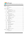
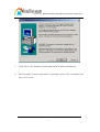
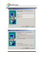
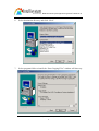
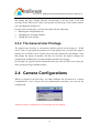
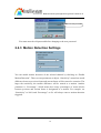
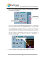
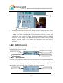
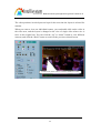
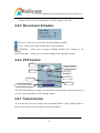
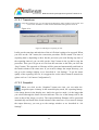
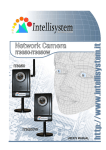
MJPEG Surveillance System Application Program User’s Manual Intellisystem Technologies S.r.l. – http://www.intellisystem.it 1 MJPEG Surveillance System Application Program User’s Manual Ver 1.0 Contents Chapter 1 Installation....................................................................................................5 1.1 Software Installation ....................................................................................5 1.2 First Startup................................................................................................10 Chapter 2 Monitor ......................................................................................................13 2.1 Features of Monitor Tool ...........................................................................13 2.1.1 Traditional Surveillance Features .....................................................13 2.1.2 Special Features ................................................................................13 2.2 Application Layout and Functionalities.....................................................13 2.3 Logging In..................................................................................................15 2.3.1 The Root Privilege ............................................................................15 2.3.2 The General User Privilege...............................................................16 2.4 Camera Configurations ..............................................................................16 2.4.1 The Layout of the Configuration ......................................................17 2.4.2 IP Settings .........................................................................................17 2.4.3 Motion Detection Settings ................................................................18 2.4.4 Alert Settings ....................................................................................19 2.4.5 Saving the Changes...........................................................................19 2.5 Global Settings...........................................................................................20 2.6 Using Monitor Tool....................................................................................22 2.6.1 Connection of the IT40x series .........................................................22 2.6.2 DI/DO Control ..................................................................................25 2.6.3 The Layout ........................................................................................25 2.6.4 Quality and Size Settings ..................................................................27 2.6.5 Record and Schedule.........................................................................28 2.6.6 PTZ Control ......................................................................................28 2.6.7 Telnet Control ...................................................................................28 2.6.8 Alert Message ...................................................................................29 2.6.9 Backup ..............................................................................................30 2.6.10 Miscellaneous Functions...................................................................30 Chapter 3 Scheduling..................................................................................................31 3.1 Invoke Scheduling Tool .............................................................................31 3.1.1 Before Start .......................................................................................31 Intellisystem Technologies S.r.l. – http://www.intellisystem.it 2 MJPEG Surveillance System Application Program User’s Manual Ver 1.0 3.2 The Layout and Functionalities .................................................................31 3.2.1 Introduction.......................................................................................31 3.2.2 The Functionalities of Each Components .........................................33 3.2.2.1 In This Section .....................................................................33 3.2.2.2 Current Year Settings and Camera Selector.........................33 3.2.3 The Schedule-Record-File operations...............................................34 3.3 Schedule with Time Lines..........................................................................35 3.3.1 Basic Controlling Skill of Time-Line ...............................................35 3.3.1.1 Scheduling Concept .............................................................35 3.3.1.2 Click.....................................................................................37 3.3.1.3 Make Serial Selection ..........................................................37 3.3.1.4 Scroll ....................................................................................39 3.3.2 Month Time-Line ..............................................................................39 3.3.3 Week Time-Line................................................................................41 3.3.3.1 Marking/Unmarking the Recoding Time .............................41 3.3.3.2 Scrolling and Switch Date in the Week Time-Line..............41 3.3.4 Day Time-Line ..................................................................................42 3.3.4.1 Marking/Unmarking the Recoding Time .............................42 3.3.4.2 Scrolling and Switch Date in Day Time-Line......................42 3.3.5 Hour Time-Line ................................................................................42 3.3.5.1 Marking/Unmarking the Recording Time............................43 3.4 Schedule with Time Picker ........................................................................43 3.4.1 Begin and End Time..........................................................................43 3.4.2 Add and Erase Buttons......................................................................44 3.4.3 Select period......................................................................................44 Chapter 4 Playback.....................................................................................................50 4.1 Features of Playback ..................................................................................50 4.2 Logging In..................................................................................................51 4.3 Layout ........................................................................................................51 4.3.1 Areas .................................................................................................52 4.3.1.1 Display Area.........................................................................52 4.3.1.2 Histogram Area ....................................................................52 4.3.1.3 Control Area.........................................................................53 Intellisystem Technologies S.r.l. – http://www.intellisystem.it 3 MJPEG Surveillance System Application Program User’s Manual Ver 1.0 4.3.1.4 Status Area ...........................................................................53 4.3.2 Indicators...........................................................................................53 4.3.2.1 Area Selection Indicator ......................................................53 4.3.2.2 Frame Selection Indicator ....................................................53 4.3.3 Pull Bar .............................................................................................54 4.4 Settings.......................................................................................................54 4.5 Normal (Single Frame) Mode....................................................................56 4.5.1 Histogram Area .................................................................................57 4.6 Preview (Multiple Frame) Mode ...............................................................57 4.6.1 Histogram Area .................................................................................58 4.7 Using Tools ................................................................................................59 4.7.1 Selector Tools....................................................................................59 4.7.1.1 Location Selector .................................................................59 4.7.1.2 Period Selector .....................................................................60 4.7.1.3 Playback Method Selector ...................................................60 4.7.2 Play Control ......................................................................................61 4.7.3 Display Adjustment Toolbox ............................................................62 4.7.3.1 Zoom In................................................................................62 4.7.3.2 Zoom Out .............................................................................63 4.7.3.3 Full Screen ...........................................................................63 4.7.4 Searching Range Adjustment Toolbox..............................................63 4.7.4.1 Zoom In................................................................................63 4.7.4.2 Zoom Out .............................................................................64 4.7.4.3 Full Range............................................................................64 4.7.5 Exporting Toolbox ............................................................................64 4.7.5.1 Transducer............................................................................65 4.7.5.2 Snapshot...............................................................................65 4.7.5.3 Print......................................................................................66 4.7.6 System Control Toolbox ...................................................................66 4.7.6.1 Lock Window.......................................................................66 4.7.6.2 Settings.................................................................................66 4.7.6.3 Exit.......................................................................................66 Intellisystem Technologies S.r.l. – http://www.intellisystem.it 4 MJPEG Video Server User’s Manual Chapter 1 Installation 1.1 Hardware System Requirement The system requirement recommended for this application is as follows. OS: MS Windows 2000 CPU: Intel 700 MHz Pentium III SDRAM: 128 MB SDRAM Hard disk: 40 GB Display Chip: nVidia, TNT, TNT2, GeForce series with 32 MB Display memory ATI Radeon series with 32 MB Display memory And following is the minimum of the system requirement for this application. OS: MS Windows 98, MS Windows ME, MS Windows XP CPU: Intel 500 MHz Pentium III SDRAM: 128 MB SDRAM Hard disk: 40 GB Display Chip: nVidia, TNT, TNT2, GeForce series with 32 MB Display memory NOTE: 1. This application software only supports Intel Pentium III or above currently. 2. If your hardware platform is not met with the minimal requirement, the response of the whole system may be lagged due to the speed limitation. 3. Since there is limitation on the application software with ATI’s display card running on Win98/ME, it is recommended that you had better run this application software with nVidia display card if you insist to run it on Win98/ME operating system. Besides, don’t use nVidia’s 28.32 WHQL driver on Win98. Please apply 12.41, 23.11 or other versions when nVidia display chip is in use on Win98. Otherwise, the response of this application software will be slow. Intellisystem Technologies S.r.l. – http://www.intellisystem.it 5 MJPEG Surveillance System Application Program User’s Manual Ver 1.0 4. Please turn off all the power management and screen saver functions to avoid the hang-up of the whole system! 5. Please also upgrade the version of DirectX to DirectX 8.1 if you are intended to run this application software with nVidia display card on Win98/ME operating system. 6. It is highly recommended to running this application software on Win2000/XP to avoid any possible functional limitation. 1.2 Software Installation This software can be installed according to the following steps: 1. Put the installation disk into your CD-ROM, and it shall run automatically. If it does not, open “My Computer” and double click on CD-ROM icon. Then ST2001 Installer window will show up. 2. There are some information in this page, including this manual, product information and the surveillance system roadmap. Click “Install” to launch install shield. Intellisystem Technologies S.r.l. – http://www.intellisystem.it 6 MJPEG Surveillance System Application Program User’s Manual Ver 1.0 3. Click “Next”, the “Software License Agreement” window will show up. 4. Please read the “License Agreement”. If you agree, press “Yes” to continue, else press “No” to exit. Intellisystem Technologies S.r.l. – http://www.intellisystem.it 7 MJPEG Surveillance System Application Program User’s Manual Ver 1.0 5. Enter user name and company name; then click “Next”. Intellisystem Technologies S.r.l. – http://www.intellisystem.it 8 MJPEG Surveillance System Application Program User’s Manual Ver 1.0 6. Select destination directory and click “Next”. 7. Select program folder to install, the “Start Copying Files” window will show up. Intellisystem Technologies S.r.l. – http://www.intellisystem.it 9 MJPEG Surveillance System Application Program User’s Manual Ver 1.0 8. Click “Next”, and the program will start to install. 9. Click “Finish” to end installation, and now the program is installed in your computer. 1.3 First Startup After you finish the installation, you can run the monitor program from “Start\ Program Files \4ch-surveillance application program\Monitor”. 1. You will be asked to set the root password first, and the password should be at least 6 characters. Intellisystem Technologies S.r.l. – http://www.intellisystem.it 10 MJPEG Surveillance System Application Program User’s Manual Ver 1.0 2. 3. 4. Press “OK” after you type the root password. A successful message box will show if you set the root password successfully. Press “OK”. An Authentication dialog will appear. You shall use the name “root” to login for the first time. Press “OK”. You will see the monitor program. Intellisystem Technologies S.r.l. – http://www.intellisystem.it 11 MJPEG Surveillance System Application Program User’s Manual Ver 1.0 5. 6. 7. From “Function Menu”, select “Global Settings” to configure the general settings for all cameras you connect (see “2.5 Global Settings” for more information). From “Function Menu”, select “Camera Configurations” to setup the configurations for each of your cameras (see “2.4 Camera Configurations” for more information). 7. After you finish these settings, here you go! Now you can run the Monitor program. Intellisystem Technologies S.r.l. – http://www.intellisystem.it 12 MJPEG Surveillance System Application Program User’s Manual Ver 1.0 Chapter 2 Monitor 2.1 Features of Monitor Tool 2.1.1 Traditional Surveillance Features The traditional surveillance features includes the features as follows: 9 Real-time monitor 9 PTZ control 9 Recording 2.1.2 Special Features Besides traditional features, in our digital surveillance system, we support the following features that make the system more powerful and convenient: 9 High quality video 9 Motion-JPEG compression 9 Maximum to 4 cameras with different monitor layouts 9 Smart playback 9 Triggered Event browsing 9 Fast data base searching 9 Auto alarm in different ways 9 Account-password protection 9 Scheduled recording for each camera 9 Just-in-time snapshot 9 AVI export 9 Motion detection for each camera 2.2 Application Layout and Intellisystem Technologies S.r.l. – http://www.intellisystem.it 13 MJPEG Surveillance System Application Program User’s Manual Ver 1.0 Functionalities This section demonstrates a global view of the monitor tool; we’ll introduce the components of the monitor tool in the following section. Misc. functions Channel area Video area DI/DO control Layout area Recording settings Hard disk status PTZ, Telnet control and Alert message There are several parts in the monitor tool: 9 Misc. functions This includes applications such as exit, snapshot, full screen monitoring, and function menu for calling global settings, configuration, and backup. The tips are provided on-line when you move the mouse cursor on them. 9 Channel area This area displays the status of each video channel, including: connection, recording, selected, and alert information. 9 Video area In this area, you can see the video of accessible channel, and some convenient Intellisystem Technologies S.r.l. – http://www.intellisystem.it 14 MJPEG Surveillance System Application Program User’s Manual Ver 1.0 9 9 9 9 9 9 9 controls. Layout area You can change monitoring layout in the layout area. Recording settings The monitor tool can record the video into hard disks. And the recording schedule is controlled with the scheduling tools. Hard disk status In this area, you can get the hard disk status. This reminds you to arrange the recorded video database. PTZ control In the area, you can do the PTZ control of selected camera. DI/DO control Receive the digital input signal and send digital output signal. Telnet control Telnet to remote camera to do low level control Alert Message Display the last alert messages 2.3 Logging In You need to login our system when starting monitor program. If you did not get an account, the monitor tool won’t be executed. There are two privileges in our account-password system: the root (administrator) and general user. 2.3.1 The Root Privilege In the monitor tool system, the root privilege can access and configure the IT40x series Intellisystem Technologies S.r.l. – http://www.intellisystem.it 15 MJPEG Surveillance System Application Program User’s Manual Ver 1.0 and change the local settings. But the root privilege is not the same as the root privilege of the IT40x series. Only if you got the root privilege of the remote camera, you can change the setting of it. If you get the root privilege, you have the right to do the following: 9 Running the configuration tool 9 Changing the recording schedule 9 Change the local settings 2.3.2 The General User Privilege The general user privilege is concurrent with the general user privilege of IT40x series. That is if you login the monitor tool as the general user, you have the right of general user of IT40x series. General users can only monitor the surveillance video and change the layout of monitor, but they do not have the right to change any configuration including the recording schedule and the local settings. If you login our system with an account that does not exist in IT40x series, then you can’t get any privilege with that camera. 2.4 Camera Configurations When you login for the first time, you shall configure the IP camera in “Camera Configurations”. Once you get the root (administrator) privilege, you can run the configuration. Attention: Before configuration, all recordings will be stopped. Intellisystem Technologies S.r.l. – http://www.intellisystem.it 16 MJPEG Surveillance System Application Program User’s Manual Ver 1.0 2.4.1 The Layout of the Configuration Camera selections In this section, we talk about the local settings only. If you are interested in the remote settings, you can refer to IT40x series user’s guide.. 2.4.2 IP Settings In the IP settings, we provide two main functionalities: Change password Add or change a IT40x series IP address and port setting 9 9 Apply – to add or change a IT40x series device. After you specify the IP address and port, click the “Apply” button. And then the system will try to connect to the IT40x series. If the connection succeeds, the root password of the remote IT40x series is required. Once you provide the correct password, the camera can be added. Password – for changing the local “root” password. Intellisystem Technologies S.r.l. – http://www.intellisystem.it 17 MJPEG Surveillance System Application Program User’s Manual Ver 1.0 Enter the old password You must enter the old password before changing to the new password. 2.4.3 Motion Detection Settings You can enable motion detection of the selected channel by checking on “Enable Motion Detection”. There are two parameters to adjust. “Sensitivity” means how much difference between previous frame and current frame will be treated as a motion. The larger the sensitivity, the smaller difference will be treated as a motion. Another parameter is “Percentage”, which means how many percentages of macro blocks between previous and current frame is designated as a motion. For example, set “Sensitivity” to 100% and “Percentage” to 0% will always cause a motion detection triggered. Intellisystem Technologies S.r.l. – http://www.intellisystem.it 18 MJPEG Surveillance System Application Program User’s Manual Ver 1.0 2.4.4 Alert Settings Some special actions can be performed such as generating an alert sound or starting recording when motion detected or digital input triggered. The digital input can be high triggered or low triggered. It depends on your setting. You can also specify the period to record after alert. 2.4.5 Saving the Changes Once you click the “Save” button, the changes in the configuration will be saved and will validate immediately. Intellisystem Technologies S.r.l. – http://www.intellisystem.it 19 MJPEG Surveillance System Application Program User’s Manual Ver 1.0 2.5 Global Settings 9 9 9 9 9 9 Snapshot directory – the directory for the storage of snapshot data. Recording directory – the directory for storing recorded video data. Reserved space – Indicate how many bytes should be reserved in the recording disk. If the recording data exceed, the new data will overwrite the oldest data. Modulation Mode – for selecting the input signal format (NTSC or PAL). Alert Sound – Select sound to play when alert. Display options – In each video frame, there are two status bars, which contain “Camera location”, “Connect time”, “Remote time” and “Record time”. All of them can be enabled here individually. Intellisystem Technologies S.r.l. – http://www.intellisystem.it 20 MJPEG Surveillance System Application Program User’s Manual Ver 1.0 Location (channel number) Remote Time Record Time (day hour:min) Connect Time (day hour:min) 9 9 Backup Settings – Select backup directory, backup size, and backup locations. You can also delete locations here. The maximum location numbers should not exceed 32. Internet Settings – Set the proxy and IP filters. Check here to enable proxy Set the proxy Check here to enable filter Add an IP address to list Delete an IP Address from list Enter IP address here to add IP list If you enable proxy server and enable IP restriction, all the IP address start with that listed in IP list will not use proxy. Intellisystem Technologies S.r.l. – http://www.intellisystem.it 21 MJPEG Surveillance System Application Program User’s Manual Ver 1.0 2.6 Using Monitor Tool 2.6.1 Connection of the IT40x series Once you have the privilege to connect to the IT40x series, you can drag and drop one camera to the video area. In the channel area, if you do not set up the camera, the color of the camera number will be gray. When you have set up the camera, you can drag and drop the camera to the video area, and use other features if you have the privileges. There is a unique light below each camera’s number. The light indicates the status of the camera: 9 Off – IT40x series is not connected. 9 Green – The green light means the IT40x series is connected. 9 Red – The red light indicates the camera is both connected and in recording mode. 9 Blink – If the motion detection is enabled and there is an alert occurred, the light will blink. Intellisystem Technologies S.r.l. – http://www.intellisystem.it 22 MJPEG Surveillance System Application Program User’s Manual Ver 1.0 Trashcan Not connected (no video) Recording Connected (monitoring) Selected channel If you don’t want to monitor one video, you can drag and drop the video (in the video area) to the trashcan. Here we’ll show the drag and drop step by step: 9 Show the video of the channel Step 1: move the mouse cursor to the channel number. Channel number Mouse cursor Location hint Intellisystem Technologies S.r.l. – http://www.intellisystem.it 23 MJPEG Surveillance System Application Program User’s Manual Ver 1.0 Step 2: Press and hold the left mouse button, the cursor will change according to the area where it is droppable. Droppable area Not droppable area Step 3: move the mouse cursor to the droppable area (in this case, it should be the video area), and then release the mouse button. In each layout, one video channel is corresponding to one and only one video box in the video area. Therefore, the drag and drop from channel number to video box also can be treat as “exchange of videos in video box”, that is if video of channel 1 is displayed at video box A, and video of channel 2 is displayed at video box B, when you drag channel 2 to video box A, then channel 2 is displayed at video box A and channel 1 is displayed at video box B. Cursor changed, video shown 9 The steps for closing the video of the channel are shown in the picture: Intellisystem Technologies S.r.l. – http://www.intellisystem.it 24 MJPEG Surveillance System Application Program User’s Manual Ver 1.0 Press and hold mouse button here. Move mouse cursor here, release the mouse button 9 The drag and drop can also apply to the change of videos. In the video area, if you want to exchange the video of different channel, you can drag the video and drop to where you want to locate the video. If the destination video box is empty, then video in the source video box will be shown on destination video box, and the source one will be empty. If the destination video box contains video of some channel, then the video in the source and destination video box will be exchanged. 2.6.2 DI/DO Control Only one user with root privilege can access the DI/DO control at the same time. Refer to the following figure to control. Set digital output to high Digital input is high Set digital output to low Digital input is low 2.6.3 The Layout There are two layouts in the monitor tool. You can select (by click left mouse button on the icon) what you want to monitor the videos. In each layout, you can drag and drop the “channel number” to any video box in the video area. If all conditions are okay, the video will be shown up in the video box and the old video is replaced. 1 camera layout 4 cameras layout Intellisystem Technologies S.r.l. – http://www.intellisystem.it 25 MJPEG Surveillance System Application Program User’s Manual Ver 1.0 The video positions in each layout are kept for the next time the layout is selected for monitor. When you want to view one individual camera, you can double-click on the video in the video area, and the layout is changed to the view of single video whose size is twice as the original one. You can click the “up” or “down” button to view different cameras, and click the “Back” button to switch to the previous selected layout. Double click on the video to switch to double size video Intellisystem Technologies S.r.l. – http://www.intellisystem.it 26 MJPEG Surveillance System Application Program User’s Manual Ver 1.0 Back to previous layout Switch between cameras 2.6.4 Quality and Size Settings There are five video qualities to choose: 9 Medium 9 Standard 9 Good 9 Detailed 9 Excellent And three video sizes to select: For NTSC, Half (172x112), Standard (352x240), Double (704x480) Intellisystem Technologies S.r.l. – http://www.intellisystem.it 27 MJPEG Surveillance System Application Program User’s Manual Ver 1.0 For PAL, Half (172x144), Standard (352x288), Double (704x576) 2.6.5 Record and Schedule Record – Allow you to record the selected channel manually. Stop – Allow you to stop recording the selected channel. Scheduling – Allow you to arrange recording schedule (see “Chapter 3” for details). Enable Scheduler – Allow you to record according to the scheduler settings. 2.6.6 PTZ Control Tilt up Return to Home Pan left Pan right Tilt down Zoom out Zoom in Go to the preset location The PTZ (Pan/Tilt/Zoom) control can control the selected IT40x series to pan, tilt, or zoom if it has connected to a PTZ enabled camera. 2.6.7 Telnet Control You can do some low level control such as manual DI/DO control, update flash etc. Please refer to IT40x series manual for more information. Intellisystem Technologies S.r.l. – http://www.intellisystem.it 28 MJPEG Surveillance System Application Program User’s Manual Ver 1.0 Telnet messages Connect Input command Disconnect 2.6.8 Alert Message If you turn on alert when motion detected of digital input triggered in configuration, the alert message will show in this window. The message format is described as follows: “time”=>”alert type” #”channel number” For example, the message “03:47:25 PM=>MO #5” means that motion detection alert occurred at 03:47:25 PM. Intellisystem Technologies S.r.l. – http://www.intellisystem.it 29 MJPEG Surveillance System Application Program User’s Manual Ver 1.0 2.6.9 Backup 2.6.10 Power Full Screen Miscellaneous Functions Local Time Snapshot Stop Alert Sound Power – Close the application and save last settings Full Screen – Switch to full screen and double click screen to return back Local Time – Display the current time Snapshot – Snapshot each view in current layout mode, and save them as bitmap file to hard disk. You can set the directory in “global settings”. Stop Alert Sound – Whenever alert occurred, the alert sound will start playing. You can press this button to stop alert sound and see alert messages. Intellisystem Technologies S.r.l. – http://www.intellisystem.it 30 MJPEG Surveillance System Application Program User’s Manual Ver 1.0 Chapter 3 Scheduling The Scheduling helps you to schedule the recoding time of the output from IP-2001. You can easily specify the time of recording via both our graphic user interface and time period selection. We provide many special features: 9 Easy to use user interface 9 One-on-one camera schedule 9 Max to 9 schedule schemes for each camera 9 Automatic period recording 3.1 Invoke Scheduling Tool 3.1.1 Before Start Remember to run the configuration tool to setup first. You need to specify the database path of the scheduling data files and the location of the camera. Please refer to chapter X for more detailed information. 3.2 The Layout and Functionalities 3.2.1 Introduction We’ll introduce the layout of the scheduler tool and its components in this section. Intellisystem Technologies S.r.l. – http://www.intellisystem.it 31 MJPEG Surveillance System Application Program User’s Manual Ver 1.0 The layout of the scheduler tool is roughly divided into 9 parts: The first part of the scheduler tool is hour time-line. It helps you make the minute based schedule. You can refer to 3.3 for more details. Part 2~4 are day time-line, week time-line and month time-line. Part 5 is the current year setting, which consists two components: year selector and set year button. Their function is changing the year that is being scheduled. Part 6 is the camera selection area, it also provide the IP addresses and location information for user’s reference. We also provide an editing schedule space for saving temporary schedule. Part 7, 8 consists of “begin time selector”, “end time selector”, “period selector”, “addition button”, and “erase button”. These components help you choose a period of time to add or delete records in the schedule. Part 9 is the operation buttons for the schedule-record-files and close window button. Intellisystem Technologies S.r.l. – http://www.intellisystem.it 32 MJPEG Surveillance System Application Program User’s Manual Ver 1.0 3.2.2 The Functionalities of Each Components 3.2.2.1 In This Section Part 1~4, and part 7~8 will be described in 3.3 and now we’ll focus on part 5~6 in section 3.2.2 and part 9 in section 3.2.3. 3.2.2.2 Current Year Settings and Camera Selector Increase year Decrease year By default, the scheduler is running with the current date selected on the time-lines and date-time picker. Therefore, the current scheduling year is the year that you run the scheduler tool. On changing the year setting, you shall follow these steps: 1. Use the up (increase) and down (decrease) arrows to adjust the year setting. 2. The date-time selector in part 7 will change the year concurrently. If user changes the year with date-time selector, the current year setting will also be changed. Although the year selection in the date-time selector is invalid when users apply the schedule change using buttons at part 8, the facility can help more flexible usage. The following is the camera selector. edit space cameras Intellisystem Technologies S.r.l. – http://www.intellisystem.it 33 MJPEG Surveillance System Application Program User’s Manual Ver 1.0 The camera selector contains two kind of items. The first one is designed for helping editing schedule, it is at row 1 of the selector. If user want to make a schedule that does not belong to any camera, he/she can select this row for editing. The second is the common camera selectors. When user click on the camera row, the scheduling tool will associate the current editing space to the current selected camera. If users have well configure the system and camera, the IP address and location will show the correct setting. Please note that when users switch between cameras, the changing of the schedule will be saved automatically. 3.2.3 The Schedule-Record-File operations There are five related buttons. Load, Clear, Save, Save as, Refresh. 9 Load This operation allows the users load other schedule from the schedule database for this camera. 9 Clear This operation will clean all the schedule markers in the current editing area. Note that users must choose “save” or “refresh” themselves. 9 Save The button is for applying the changes for the current schedule. 9 Save As If the users want to save the current schedule-record-file to another file name, the button will serve this necessary. 9 Refresh When users click on this button, the scheduling tool will load the old data from the schedule-record-file. The current changes will be lost. Intellisystem Technologies S.r.l. – http://www.intellisystem.it 34 MJPEG Surveillance System Application Program User’s Manual Ver 1.0 3.3 Schedule with Time Lines There are four time-lines: hour unit time-line, day unit time-line, week unit time-line and month unit time-line. You can make your schedule in all time-lines. These four time lines are related to the same database, that is, if you have rescheduled one time-line, the changes will be applied to the other three corresponding time-lines. 3.3.1 Basic Controlling Skill of Time-Line 3.3.1.1 Scheduling Concept 9 Time Unit Each time-line has its own basic marking unit, that is, if you make your schedule on different time-line, the result is much different. The basic design philosophy of the scheduler tool is that one unit means: X≤ unit X < X + 1 unit For example: When the mouse is at hour time-line, and the time information is 10:00, we take it as X. The X + 1 unit is 10:05 If you click the left mouse button on the hour time-line as the time information, 10:00, then the recording time is Intellisystem Technologies S.r.l. – http://www.intellisystem.it 35 MJPEG Surveillance System Application Program User’s Manual Ver 1.0 10:00 ≤ recording time < 10:05 Five minute recording record Five minutes recording record within 20 minutes Five minutes recording record within one hour Five minutes recording record within half day 9 The marking concept is that there exists different time unit of each time-line. If there is any smallest time unit, which is marked for recording, then the time unit for each time-line contains the time will be marked. For example: In hour time-line, 1:10~1:15(include lower bound, exclude upper bound) is marked, although only in 1:10~1:15 the recording is validate. As situation of point 1, in day time-line, 1:00~1:20(include lower bound, exclude upper bound) is marked, although only in 1:10~1:15 the recording is validate. As situation of point 1, in week time-line, 1:00~2:00 (include lower bound, exclude upper bound) is marked, although only in 1:10~1:15 the recording is validate. As situation of point 1, in month time-line, 00:00~12:00 (include lower bound, exclude upper bound) is marked, although only in 1:10~1:15 the recording is validate. Mouse buttons The scheduler tool is designed for two-button mouse. In this user’s guide, we use left mouse button and right mouse button to distinguish them. When you click or double click the left mouse button over the time-line, the time-line will mark the time for the scheme of the schedule; if you click or double Intellisystem Technologies S.r.l. – http://www.intellisystem.it 36 MJPEG Surveillance System Application Program User’s Manual Ver 1.0 click the right mouse button over the time-line, the time-line will unmark (clear) the record in the scheme of the schedule. In other word, operations over time-lines which are left mouse button based are designed for marking the time (make a record, red bars on time-line) in the scheme of schedule, and the operations which are right mouse button based are designed for cancel the record (unmark the time, green bars on time-line) in the scheme of schedule. 3.3.1.2 Click When you move your mouse over the time-lines, the scheduler will show the date/time information under the cursor to remind you of what’s the time at the mouse cursor position. Click Marked 3.3.1.3 Make Serial Selection If you want to mark/unmark a serial of time units, the following steps demonstrate the method. Step 1: Press and hold the left mouse button Intellisystem Technologies S.r.l. – http://www.intellisystem.it 37 MJPEG Surveillance System Application Program User’s Manual Ver 1.0 Step 2: Note the time information from the tips and move the mouse to the target time Step 3: Release the left mouse button Intellisystem Technologies S.r.l. – http://www.intellisystem.it 38 MJPEG Surveillance System Application Program User’s Manual Ver 1.0 In the example, you mark the time interval from 00:40 to 23:40 that means you had marked the time: 00:40 ≤ the time < 23:40 + 1 unit of day time-line ( = 24:00) If you press the right mouse button in the above steps, the scheduler tool draw a green bar in the time-line, and finally clear the records in the unmarked region. 3.3.1.4 Scroll The hour time-line, day time-line and week time-line contain two scrolling area. Area for scroll to right Area for scroll to left Whenever you move the mouse cursor into these areas, the contents of the time-lines will scroll to different time area which is depending on the area where the cursor locates. It does not matter whether the mouse button is pressed or not. 3.3.2 Month Time-Line Cursor Non-selected month Intellisystem Technologies S.r.l. – http://www.intellisystem.it 39 MJPEG Surveillance System Application Program User’s Manual Ver 1.0 Selected month Date/Time information Since the scheduling tool is a year based scheduler, you can’t do cross year schedule in the same time. Your must schedule each year one by one. There are different ways to mark/unmark the recording periods: Click the left button of mouse and a half-day period is marked. That means from 0:00 to 11:59 or from 12:00 to 23:59, the digital video signals will be saved in the hard disk only when you run the monitor software. Step 1: Click mouse left button Step 2: After click Intellisystem Technologies S.r.l. – http://www.intellisystem.it 40 MJPEG Surveillance System Application Program User’s Manual Ver 1.0 If you press and hold the left mouse button and then moving the mouse pointer, a serial of half-day schedule will be marked after you release the left mouse button. If the right mouse button is clicked or pressed, the time-line will help you to unmark the schedule. 3.3.3 Week Time-Line Selected week Right scroll area Selected day Left scroll area Cursor Date/time information 3.3.3.1 Marking/Unmarking the Recoding Time The one-click unit of week time-line is one hour. It means a continuous one-hour recording schedule is markedunmarked if you click the mouse button. You can also press and hold the mouse button to mark/unmark continuous units. Result in day time-line Result in hour time-line Click Result in month time-line 3.3.3.2 Scrolling and Switch Date in the Week Time-Line If you move the mouse cursor to the most left part of the time line, the time-line will scroll one day-unit at a short time, and the earlier date will be shown in the week time-line, and vice versa. When left mouse button click happens at upper time-line area (the week day indicator), Intellisystem Technologies S.r.l. – http://www.intellisystem.it 41 MJPEG Surveillance System Application Program User’s Manual Ver 1.0 the current date selection is changed, and the change also has its effect in all other time-lines. 3.3.4 Day Time-Line Selected day Scroll to right area Cursor Scroll to left area Time information of current cursor 3.3.4.1 Marking/Unmarking the Recoding Time The one-click time unit in day time-line is 20 minutes. The operating method is the same as week time-line and month time-line. Please refer to 2.3.1 and 2.3.2 for more details. 3.3.4.2 Scrolling and Switch Date in Day Time-Line Moving mouse cursor to the most left part of the day time-line will cause the time-line to scroll one day earlier. If you keep the mouse cursor within the same area, the time-line will continue scroll and vice versa. Click at the day information area of day time-line will cause the selected day to be changed and the change will also take its effect on other time-lines. 3.3.5 Hour Time-Line Left scroll area Non-selected day Right scroll area Selected day Intellisystem Technologies S.r.l. – http://www.intellisystem.it 42 MJPEG Surveillance System Application Program User’s Manual Ver 1.0 3.3.5.1 Marking/Unmarking the Recording Time The one-click unit in hour time-line is five minutes, and it’s also the smallest unit of the scheduling tool. The operating method is the same as the other three time-lines. Please refer to 2.3.1.1 or 2.3.2.1 for more details. Scrolling and Switch Time in Hour Time-Line The scrolling unit of hour time-line is one hour. Moving the mouse cursor to the left-most part of the time-line will scroll the time-line to earlier time and vice versa. The selection unit of this time-line is one day, that is, when you click on the hour information area in the time-line, the selected day will be changed and the other three time-lines will be changed as well. When you move your mouse over the hour-line, the scheduler tool will show the time of the current cursor position. It gives a great help to make detailed schedule. Cursor Time of the cursor position 3.4 Schedule with Time Picker 3.4.1 Begin and End Time There are three controlling units in both the start and end time selectors. The first controlling unit is the date picker. You can select the year, month and day with it. Once you select the date in different year, the data file will switch automatically. Remember to make the begin time earlier than the end time. Otherwise the add action Intellisystem Technologies S.r.l. – http://www.intellisystem.it 43 MJPEG Surveillance System Application Program User’s Manual Ver 1.0 will be ignored. 3.4.2 Add and Erase Buttons After you have selected time period with the begin time and the end time picker, you can click the “Add” button or “Erase” button to add or clear the scheduling information within the time period. Remember that only if you click on the “Apply” button, the scheduling changes will be written back to the data file. It means the scheduling is valid only if you “Apply” the changes. Add Erase 3.4.3 Select period 9 Once If you select “once” option, the scheduler tool will mark the time according to the begin time and end time. It includes year, month, day, hour, and minute selections. The following picture illustrates this situation. Intellisystem Technologies S.r.l. – http://www.intellisystem.it 44 MJPEG Surveillance System Application Program User’s Manual Ver 1.0 9 Every hour If this option is selected, only the selection of minutes is valid. And within the whole year, every minute that meet the setting will be marked. The situation is shown below: Intellisystem Technologies S.r.l. – http://www.intellisystem.it 45 MJPEG Surveillance System Application Program User’s Manual Ver 1.0 9 Every day If you select this option, only the selection of hour and minute is validated. And the time that meets the selection will be marked within the year. Take the result shown below as an example. Intellisystem Technologies S.r.l. – http://www.intellisystem.it 46 MJPEG Surveillance System Application Program User’s Manual Ver 1.0 9 Every week The functionality is similar to other options. The scheduler tool will check the dates for their day of week, and apply the time mark to every week within the year. Remember one thing – only the day of week, hour and minute are valid. Intellisystem Technologies S.r.l. – http://www.intellisystem.it 47 MJPEG Surveillance System Application Program User’s Manual Ver 1.0 Wednesday Thursday 9 Every month In this option, only the date (exclude the month and year), hour and minute are valid. Therefore the result is as fellows: Intellisystem Technologies S.r.l. – http://www.intellisystem.it 48 MJPEG Surveillance System Application Program User’s Manual Ver 1.0 Intellisystem Technologies S.r.l. – http://www.intellisystem.it 49 MJPEG Surveillance System Application Program User’s Manual Ver 1.0 Chapter 4 Playback 4.1 Features of Playback The playback program we provide here is a very powerful, convenient, and easy using tool to assist you in browsing the recorded video database. It has two display modes (normal display mode, preview mode) and three playback methods (full range, time period, events preview). The main tools it provides include: 9 Powerful play control tool: Play Stop Pause Step forward Fast play (from x1 to x16) Slow play (from /1 to /16) 9 Convenient display adjustment tool: Zoom in (from 1:1 to 2.25:1) Zoom out (from 1:1 to 1:2) Full screen 9 Flexible searching range adjustment tool: User input (from full range to 1 second) Zoom in (from full range to 10 seconds) Zoom out (up to full range) Page searching Full range 9 Various exporting tool: AVI file transducer BMP file snapshot Output to printer directly Intellisystem Technologies S.r.l. – http://www.intellisystem.it 50 MJPEG Surveillance System Application Program User’s Manual Ver 1.0 4.2 Logging In Before you start the playback program, it is necessary for you to login our system. Figure 4-1 shows the login dialog. For the security concern, only the root account can login this program. To change the password of root account, please refer to “2.3 Logging In”. Figure 4-1 Login dialog 4.3 Layout Area Selection Indicator Display Area Control Area Pull Bar Histogram Area Status Area Intellisystem Technologies S.r.l. – http://www.intellisystem.it 51 MJPEG Surveillance System Application Program User’s Manual Ver 1.0 Figure 4-2 Playback main window Once you login the playback system successfully, the main window will be shown on the top of the screen and the display resolution will change to 1024x768 automatically (Figure 4-2). There are four main areas in that window, i.e. display area, histogram area, control area, and status area. There are also three visualized control in it, i.e. area selection indictor, frame selection indictor, and pull bar. These features provide you much more convenience to search the surveillance database. 4.3.1 Areas 4.3.1.1 Display Area The display area shows the surveillance database of each camera by events triggered by the alert or by time. You can change the video size through the display adjustment tool and the playback method through the play control tool. Under the normal display mode as shown in Figure 4-3, you can just double click on the frame area to change the frame size to 1:1 or 2.25:1. And in the preview mode, double clicking on any frame area can change the display mode to normal and show the 10-second interval including the event you selected. Frame Selection Indicator Page Control Figure 4-4 Display by event (preview mode) Figure 4-3 Display by time (normal display mode) 4.3.1.2 Histogram Area The histogram is an interactive control. Not only you can get the event’s location in time domain and its motion quantity, but also you can select a group of events or period from the event histogram area and show it on the display area. Intellisystem Technologies S.r.l. – http://www.intellisystem.it 52 MJPEG Surveillance System Application Program User’s Manual Ver 1.0 4.3.1.3 Control Area The control area contains almost all the control selectors and toolboxes you need to browse the database except the page control. The page control tool is located on the right-bottom corner of the display area when the program is operating in the preview mode (shown in Figure 4-4). These control tools include location selector, period selector, playback method selector, jog dial, display adjustment tool, searching range adjustment tool, exporting tool, and system control tool. In “4.7 Using Tools”, we will discuss these in more details. 4.3.1.4 Status Area The status area is located at the bottom of the main window. It tells you all about the program statuses including display mode, display size, display speed, exporting file format, and exporting file name. 4.3.2 Indicators 4.3.2.1 Area Selection Indicator In Figure 4-2, the display area is surrounded by a yellow rectangle. This rectangle is the area selection indicator. This indicator can set to either display area or histogram area, as long as you move your mouse cursor to the area you want to select. When you select the display area, the display adjustment tool will appear in the control area, and if you select the histogram area, the display adjustment tool will disappear and the searching range adjustment tool will be shown in the control area. 4.3.2.2 Frame Selection Indicator The frame selection indicator only appears when you change the display mode to preview mode (as shown in Figure 4-4). It is a red rectangle surrounding to one of the nine event preview frames. Once you select one of these frames, you can control its play status through the jog dial in the control area. Intellisystem Technologies S.r.l. – http://www.intellisystem.it 53 MJPEG Surveillance System Application Program User’s Manual Ver 1.0 4.3.3 Pull Bar The pull bar is a fast, flexible control for seeking data in the selected time period. It represents the total length of time in that period. You can click or pull the indicator on the pull bar to the point you want to see. And the displaying video will halt and restart to play the video sequence from the point you choose. If the video sequence has been paused, the display area will show the point you select without playing. The pull bar will only function under the normal display mode. 4.4 Settings After the main window is shown on the screen, you must modify the settings to make it work properly. Click on the “Settings” button in the system control tool, and the setting dialog will appear on the screen as shown in Figure 4-5. Figure 4-5 Settings dialog 9 Database path The most important item in the settings dialog is the database path setting. You Intellisystem Technologies S.r.l. – http://www.intellisystem.it 54 MJPEG Surveillance System Application Program User’s Manual Ver 1.0 must set it to the directory that contains the surveillance database to make the program work properly. 9 AVI file location It sets the storing directory when you export AVI files. These exporting AVI files will be stored in the sub-directory under the directory you set here with the name of the location you select. 9 Bitmap file location It sets the directory when you use the snapshot to export bitmap files. These exporting bitmap files will be stored in the sub-directory under the directory you set here with the name of the location you select. 9 Bitmap color depth This setting changes the color depth of the exporting bitmap file. It is suggested to use more than 16 bits color depth to get the better picture quality. 9 AVI compression mode Unlike the exporting of bitmap file, we use only 16 bits color depth to export the AVI file. During the AVI compression mode selection, you can select one of the compression methods that your computer supports to export the AVI file. 9 Modulation mode The modulation mode can’t be changed uninhibited. It depends on how you recorded the video sequence in the monitor program. If you select the wrong mode, the video shown in the display area will become deformed. Under that situation you choose the wrong modulation mode, you may open the settings dialog again, change to the correct mode, and restart the playback program, then it will display properly. 9 Control panel position It provides you a very convenient method to change the position of the control area to fit your habit. Once you change the setting of modulation or control panel position, you have to restart the program to take these changes into effect. And if you set the database path correctly, the video sequence will start displaying in the normal display mode when you click on the “Ok” button. Intellisystem Technologies S.r.l. – http://www.intellisystem.it 55 MJPEG Surveillance System Application Program User’s Manual Ver 1.0 4.5 Normal (Single Frame) Mode You can enter the normal mode when you: 9 Change the database path in the settings dialog 9 Change the location selector to another location 9 Change the playback method selector to “Full Range” 9 Change the playback method selector to “Time Period” 9 Double click on one of the nine frames in the display area under the preview mode. Period Start Time Label Period End Time Label Figure 4-6 Normal display mode Under the single frame mode, you can use all the tools the playback program provided except the page control. In this mode, the two labels under the pull bar show the start and end time of the period individually (as shown in Figure 4-6). Intellisystem Technologies S.r.l. – http://www.intellisystem.it 56 MJPEG Surveillance System Application Program User’s Manual Ver 1.0 4.5.1 Histogram Area Dark Region Inverted Region Figure 4-7 Histogram area in normal display mode The histogram area in the single frame mode only shows the events’ occurred time and the percentage of motion detection with red bars. If you want to access the histogram area, you must change the area selection indicator to the histogram area. You can select a color-inverted region by dragging your mouse with left button pressed (as shown in Figure 4-7). When you release the left button, the color-inverted region will be enlarged to the whole histogram area. This color-inverted region will be the new period the program is going to display. If you change your mind and don’t want to see that period, you can cancel it by just pressing the right button of your mouse with the left button still pressed. If you click on the left button without dragging it, the action will be the same as clicking on the pull bar in the same x-axis position. The dark regions mean there is no video data existed in that interval. If you click on those regions, nothing will happen except a warning message. 4.6 Preview (Multiple Frame) Mode You can enter the preview mode only when you change the playback method selector to “Events Preview”. It can help you to identify the objects triggering the events via not only the time information and the alert percentage but also the real video preview playing. With it, you can easily tell the different alert situations. Under the preview mode, the pull bar, “Transducer” button in exporting toolbox, and the display adjustment toolbox are disabled. The two labels under the pull bar show the displayed event number and the total event count individually. There are nine frames in the display area that we call it one page. And each frame displays a 10-second interval video sequence with /4 slow speed that contains different events. You can use the “Page Up” and “Page Down” button in the page control to browse the events in the selected period with nine events per page. And the page status tells you the current Intellisystem Technologies S.r.l. – http://www.intellisystem.it 57 MJPEG Surveillance System Application Program User’s Manual Ver 1.0 page number and total page count (as shown in Figure 4-8). Page Status Page Up Displayed Event Total Event Count Page Down Figure 4-8 Preview mode 4.6.1 Histogram Area The histogram area in the preview mode not only shows the events’ occurred time and value with red bars, but also tells you the current displayed events with green bars and the selected event with blue bar. If you want to access the histogram area, you must change the area selection indicator to the histogram area. You can select a color-inverted region by dragging your mouse with the left button pressed (as shown in Figure 4-9). Inverted Region Dark Region Figure 4-9 Histogram area in preview mode When you release the left button, the color-inverted region will be enlarged to the Intellisystem Technologies S.r.l. – http://www.intellisystem.it 58 MJPEG Surveillance System Application Program User’s Manual Ver 1.0 whole histogram area. This color-inverted region will be the new period the program is going to display. If you change your mind and don’t want to see that period, you can cancel it by just pressing the right button of your mouse with the left button still pressed. If you click on the left button without dragging it, the display area will show the event page closest to the point you select. The dark region means there is no video sequence existed in that interval. If you click on those regions, nothing will happen except a warning dialog. 4.7 Using Tools 4.7.1 Selector Tools Figure 4-10 shows the selector tools, they are location selector, period selector, and playback method selector. Figure 4-10 Selector tools 4.7.1.1 Location Selector The location selector is a control that lets you select the camera you want to see (refer to Figure 4-10). The location information is the same as the location when you specify in the monitor program (see “2.5 Global Settings”). If there is more than one database Intellisystem Technologies S.r.l. – http://www.intellisystem.it 59 MJPEG Surveillance System Application Program User’s Manual Ver 1.0 in the same location, another dialog will appear (as shown in Figure 4-11). And you must select an interval in that dialog. If your selection is correct, the playback program will automatically switch to that camera and start displaying. Figure 4-11 Time interval selection dialog 4.7.1.2 Period Selector Period selector provides you a precise way to choose the start time and the end time of a new period. The end time should be larger than the start time. After you give the correct start and end time, clicking on the “Play” button in the jog dial will play the new period in the display area, change the period start and end time label, the pull bar and histogram area will change, too. If the selected period is not present in the database, the data in the period selector will change to the previous correct start and end time and a warning message will be displayed. 4.7.1.3 Playback Method Selector 9 9 9 Full Range If you select this method, the database will be displayed from the beginning to the end of this location. Any change in the period selector will take no effect except you change this selector to “Time Period”. Time Period If you change the playback method to “Time Period”, you can modify the start and end time in the period selector. When you click on the “Play” button in the jog dial, the period you select will be displayed. Events Preview This method will change the display mode from the normal display mode to the Intellisystem Technologies S.r.l. – http://www.intellisystem.it 60 MJPEG Surveillance System Application Program User’s Manual Ver 1.0 preview mode. Since the program will record the previous start and end time in “Time Period” and “Events Preview” mode. Any time you want to change the period selector to see another period, you must change the playback method selector to the mode you want to use first. Otherwise, the period selector will back to the previous data when you change the playback method selector. 4.7.2 Play Control For the play control, we used a jog dial to provide the easiest way to control the displaying video sequence. Except the “Play” button, all other buttons can control the displaying frame in the normal display mode and the selected displaying frame in the preview mode. Speed Indicator Pause Play Step Forward Stop Figure 4-12 Jog dial 9 9 9 Play The “Play” button we support here is an intelligent play interface. The functionality of this button can vary to fit with different circumstance. In the normal display mode, click on the “Play” button can restart the displaying video sequence. When in the preview mode, if you don’t change the data of period selector, click on this button only restarts the selected displaying frame. If the data of the period selector has been changed, clicking on the “Play” button will restart all frames to display the first nine events in the new period. Stop When you want to stop the displaying video sequence, you can click on the “Stop” button. Once you had pressed the “Stop” button, the start point will be reset to the start of the present period. Pause Intellisystem Technologies S.r.l. – http://www.intellisystem.it 61 MJPEG Surveillance System Application Program User’s Manual Ver 1.0 9 9 The “Pause” button provides you a way to pause the displaying video sequence. When the displaying video is paused, click on the “Pause” button again will continue the video to display. Step Forward This button is only valid when the displaying video sequence is paused. It will display the next frame in that period when you click on the “Step Forward” button one time. Fast Play and Slow Play We support maximum to x16 fast forward play and minimum to /16 slow forward play. This function helps you browse the surveillance database more flexible. If you want to change the playing speed, you just need to move the speed indicator. To increase playing speed, move the indicator in the clockwise direction. And to decrease playing speed, move it in the counterclockwise direction. Current speed you set will be shown in the second column of status area. 4.7.3 Display Adjustment Toolbox Using the display adjustment toolbox, you can change the displaying video sequence to the size you want to see in the normal display mode when you move the area selection indicator to the display area. Figure 4-13 shows the display adjustment toolbox and its own three elements, i.e. “Zoom In”, “Zoom Out”, and “Full Screen”. Figure 4-13 Display adjustment toolbox 4.7.3.1 Zoom In When you click on the “Zoom In” button one time, the image size in the display area will be magnified 12.5 percent to the original size. Due to the limitation of the display area size, the maximum zoom in ratio we support here is only 2.25:1 for NTSC modulation mode and 1.875:1 for PAL modulation mode. If you want to see the image in more details, you can use the full screen function we support in the same toolbox. Intellisystem Technologies S.r.l. – http://www.intellisystem.it 62 MJPEG Surveillance System Application Program User’s Manual Ver 1.0 4.7.3.2 Zoom Out When you click on the “Zoom Out” button one time, the image size in the display area will be minified 12.5 percent to the original size. To show the location and time information completely, the minimum zoom out ratio is limited in 0.5:1. 4.7.3.3 Full Screen When you click on the “Full Screen” button, the video sequence will be enlarged to the whole screen instantly. You can double click on any place to return to the original state. When you switch to full screen display, you can press the “alt” and “space” keys together to pop the jog dial to control the displaying video sequence. Press the same keys again will close the jog dial. You can also press the “alt” and “enter” keys together to switch between the normal display and full screen display at any time when the program is under the normal display mode. 4.7.4 Searching Range Adjustment Toolbox The searching range adjustment toolbox provides you a faster way to change the range of the displayed time period. By using this toolbox, you can browse the database of one location from any 10-second interval to the entire range. Figure 4-14 shows the searching range adjustment toolbox with its own three elements, i.e. “Zoom In”, “Zoom Out”, and “Full Range”. Figure 4-14 Searching range adjustment toolbox 4.7.4.1 Zoom In Each time you click on the “Zoom In” button in the searching range adjustment toolbox, the displayed time period will be half in the center of the original time period until the period is equal to 10 seconds. You can see the new interval in more details. The scale of pull bar and alert histogram window changes and Intellisystem Technologies S.r.l. – http://www.intellisystem.it 63 MJPEG Surveillance System Application Program User’s Manual Ver 1.0 the period start and end time change, too. The period selector will show the new start and end time. And the display area will restart to display the new period from the new start time. 4.7.4.2 Zoom Out Each time you click on the “Zoom Out” button in the searching range adjustment toolbox, the displayed time period will be double in the center of the original time period unless the start time or end time exceeding the database boundary. The scale of pull bar and alert histogram window changes and the period start and end time change, too. The period selector will show the new start and end time. And the display area will restart to display the new period from the new start time. 4.7.4.3 Full Range As you click on the “Full Range” button, you will get the same functionality just like you change the playback method selector to “Full Range”. 4.7.5 Exporting Toolbox In our playback program, you not only can check the database through our program but also can export the database to other media. Using the exporting toolbox, you can export the database to other more portable formats, such as avi file, bitmap file or paper. Then you may use windows media player or other program to browse the exporting data. Under the normal display mode, you can use all the exporting tools. And under the preview mode, only snapshot and print can be used. Figure 4-15 shows the three elements of the exporting toolbox, i.e. “Transducer”, “Snapshot”, and “Print”. Figure 4-15 Exporting toolbox Intellisystem Technologies S.r.l. – http://www.intellisystem.it 64 MJPEG Surveillance System Application Program User’s Manual Ver 1.0 4.7.5.1 Transducer Using the transducer tool, you can transpose the displaying video sequence to the avi file. Just click on the “Transducer” button and an information dialog will be shown as Figure 4-16. Figure 4-16 Dialog for exporting avi file It tells you the start time and end time of the avi file that is going to be exported. When you click on the “Ok” button, the conversion procedure will be started. The time of exporting data is depending on how fast the processor you used. During any time of the exporting interval, you can click on the “Stop” button in the jog dial to stop the procedure. Then you will get an avi file from the start time to the time you click the “Stop” button. The exported avi filename will be generated automatically and listed in the fourth column of the status area. If you want to change the output directory, you can go to the settings window as we described in “4.4 Settings”. To get the better quality of the exporting AVI file, it is suggested to set the video format to normal size (please refer to “2.4 Camera Configurations”). 4.7.5.2 Snapshot When you click on the “Snapshot” button one time, you can make the program export a bitmap. In the normal display mode, the exporting bitmap is the image shown in the display area. And in the preview mode, it is the image that you selected through the frame selection indicator. The size of the bitmap will be the same as that of the image you select. The exported bitmap filename will be generated automatically and listed in the fourth column of the status area. If you want to change the output directory, you can go to the settings window as we described in “4.4 Settings”. Intellisystem Technologies S.r.l. – http://www.intellisystem.it 65 MJPEG Surveillance System Application Program User’s Manual Ver 1.0 4.7.5.3 Print When you click on the “Print” button, a printing dialog will be appeared. After you made your selection and send to the printer, the images on the display area will be printed out. The printing functionality is designed based on the idea, “what you see is what you get”. Therefore, the output data will be the same as what is in the display area. 4.7.6 System Control Toolbox The system control toolbox provides you some basic operations for the playback program. Figure 4-17 shows the three elements of the system control toolbox, i.e. “Lock Window”, “Settings”, and “Exit”. Figure 4-17 System control toolbox 4.7.6.1 Lock Window If you want to leave away from your computer, for the security concern, we suggest you to close the playback program or you can just click on the “Lock Window” button to lock the main window. Once you click this button, the main window will be hided and the login dialog will appear (as shown in Figure 4-1). To return to the main window, you need to enter the root’s password again. 4.7.6.2 Settings The settings dialog will pop up when you click the “Settings” button. For more information about setting this program, please refer to “4.4 Settings”. 4.7.6.3 Exit The playback program will be terminated immediately when you click on the “Exit” button. If the avi exporting procedure is running, this procedure will be stopped first. Intellisystem Technologies S.r.l. – http://www.intellisystem.it 66