1
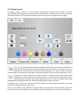
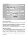
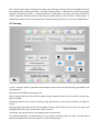
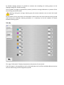
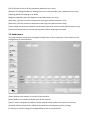
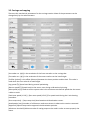
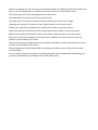
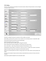
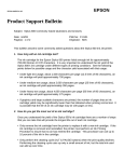
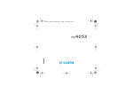
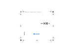
MS JP6
USER’S MANUAL
1 Introduction
The JP6 in the entry level of the innovative MS fabric printer family.
JPK is equipped with the latest generation of KJ4 Kyocera printing heads and is available in several
models from 4 to 8 colours.
The use of the machine is easy, intuitive and exactly alike for all the models, thanks to its easy -to
-use touch-screen panel.
The JP6 ofers all the advanced functionalities of industrial production machines together with the
easy management of an office plotter.
The printer communicates with the outside and with the printing RIP by a 10 GbE-CX4 port.
1.1 Responsibility and user license
MS srl reserves the right to modify, without prior notice, the machine and its sofware, with the
object to improve its performance.
Its sofware is supplied under “ User license” and cannot absolutely be copied or reproduced
without written specific MS srl authorization.
This manual cannot be reproduced ,completely or partially ,without specific MS srl authorization.
MS srl. , although having used the utmost care in the development of the machine, of its sofware
and this manual declines any responsibility for their inadequate or improper use.
MS srl. cannot be held responsible in any way for any business loss or profits loss or damages
related to improper use of the machine.
In no case MS srl can be held responsible for any damage related to output loss caused by possible
failures.
The user is not authorized to modify, in any way, the machine and its mechanical, electrical parts
and sofware..
MS srl. declines any responsibility for possible bad workings due to modifications on the machine.
It’s absolutely forbidden to use the machines without the safety devices provided at the
installation.
MS srl. declines any responsibility related to incidents happened in absence of safety devices.
1.2 Operating environment
The printer is designed to work with an environment temperature within 20 and 30 degrees with a
relative humidity within 45 and 65 %. Outside these parameters it is not possible to ensure the
right performance of the inks.
It is also absolutely necessary to check the belt adhesive status before starting to print, warming it
up if necessary. The fabric detachment during the printing process can cause damages on the
heads carriage not covered by the warranty.
2 Commands, switch on/off
The switch on/of are activated by the general switch positioned on the rear electrical board door.
Note: before switching of the printer , check that the carriage is in “ home” position and
that the capping is properly closed
Attention: the proper printer working requires compressed air feeding; if the correct air
feeding is missing the ink pressure on the heads cannot be kept with possible colour
leakages.
At the switch on ,the inside computers perform the diagnostic procedure and the sofware loading;
in this phase the control panel will look black for some seconds. Afer the loading the system
sofware will perform the external components diagnostics procedure, and, in absence of errors,
the screen will display as in the following page.
Most of the functions are managed by the touch screen on the right front part of the machine.
Beside the touch-screen some service buttons are positioned on rear part to make easier the fabric
introduction.
Emergency push buttons are located in every part of the machine as well as the buttons to put the
printing in “pause”.
Note: in case of pressing a pause button the printing can be reactivated only by the front
panel board, for obvious safety reasons.
In case of pressing an emergency button the machine will stop immediately. To restart the
running ,all the engaged emergency buttons must be released and the reset blue button aside the
control panel must be pressed.
Attention: the printer is equipped with safety sensors on front lids, on lateral doors and on
the rear lid of the fabric feeding. Blocking or deactivating the closing doors sensors is strictly
forbidden. The printing carriage is more than 50 kilos heavy and runs at over one meter per
second and, therefore, it can be very dangerous. Working on the machine with open lids is
absolutely forbidden.
Pressing the “Play” icon the machine will perform the initialization cycle of the mechanical
running. Pressing the “Maintenance” icon you will enter the reserved area of the machine
parameters. Access to this area is protected by a password for the authorized technical personnel.
In case of error in the initialization procedure the screen will display the error code and a short
description of the problem beside a series of buttons.
The buttons shown change according to the error. The possible options are the following:
[Continue] It means that the error does not compromise the safety and that you can proceed with
the normal initialization procedure. The component at the origin of the error could respond not
properly . Therefore the printing could not be possible and a diagnostics of the problem is
necessary.
[Restart] The error compromises the proper functionality of the machine and must be diagnosed
by qualified personnel with the help of external appliances.
[Maintenance] It’s displayed in case of an important error and it allows the access to the
diagnostics phase reserved to authorized personnel.
[Try again] It shows a temporary error that can be solved by restarting the initialization.
In case of successful initialization the screen of the control panel will display like below.
2.1 The main panel
This page is called “ Pause” or “local” because the machine responds only to orders from the
control panel ignoring data and print requests from RIP. Besides, it shows the status of the machine
and allows the control of the main functions and the access to the management sub-pages.
The “ Pause” button allows to stop the machine and to enter the main menu functions. If
kept pressed during the printing the carriage stops at the end of the carriage scan. So it’s
possible the manual motion of the belt (fold skipping) or to open the lids to remove
possible folds on the way of the carriage or the heads cleaning. To restart the printjob press “Play”
Pressing the “Play” button the machine enters in remote control mode and the RIP
sofware can transfer data for the printing request. The same key can be used to restart
a printing afer the pause. On the displayed page there are only the options that can be
changed while printing like the fabric feeding compensation and the anti foam.
In the upper part, info on the machine status are indicated as well as the kind of fabric, the name
of the file in printing and the mode used.
The two text fields in the middle of the page allow to set the origin of the printing, that is the
point where the carriage begins to print and the width of the fabric. The values are in millimeters.
The four keys with the blue arrows allow the manual positioning of the carriage and the belt;
these keys must be kept pressed while the two keys with the black arrows activate the belt
advancement in continuous in both directions.
When the lids are open the shifing buttons of the carriage are deactivated.
The “ Fabric” icon allows to enter the page of fabric parameters setng described in the
paragraph 2.2.
The "“Cleaning” icon allows to enter the “ Test draw” page, head cleaning and carriage
maintenance of paragraph 2.3
The “ Info” icon shows the page of additional info described in the paragraph 2.4. SPAZIO
PER FORMATTAZIONE
The “ Setngs” icon recalls the presets and configurations as in par 2.5. SPAZIO PER
FORfsdfsd
The “Maintenance” icon gives access to the restricted maintenance and machine
parameters menus described int the chapter 3.
The “Abort” icon (displayed in the upper right part only during the printing) allows to
terminate the current printjob.
In the lower part of the page there are the icons of the loaded inks and some status indicators of
the machine.
The inks icons alternate with the icons below to indicate possible problems or intervention
requests from the operator.
This icon shows that the fashing colour is exhausting. Its level must be restored in order to
go on with the printing. If this operation has not been performed in a few minutes the
printer will pause automatically and it is not possible to go on until the ink level is restored.
This icon indicates that the colour has not achieved the working temperature. Heads are
provided with an inside warmer to adjust the temperature. If the indication lasts more than
one minute call for the technical assistance.
This icon indicates that the colour has exceeded the maximum temperature allowed by the
heads. If the indication persists for more than one minute call for the technical assistance.
This icon indicates that the negative pressure on the heads is over the allowed level. In this
situation heads are unable to print. If the indication remains call for the technical assistance.
This icon indicates that there is a positive pressure on the heads. In this situation heads tend
to drip and it’s not possible to print. If the indication persists call for the technical
assistance.
The following fashing indicators can appear on the right side of the panel:
The unwinder is provided with a photocell monitoring the presence of the fabric. The
display of this icon indicates that the fabric is over or not loaded . During the printing the
machine goes in pause automatically in order to load again or change the fabric.
It indicates that a wrinkle has been monitored on the fabric or that the selvedges are not
sticked to the belt. The machine enters in pause and a manual intervention is necessary
to remove the wrinkle.
Some buttons for the activation of the following functionalities are positioned in the lower part of
the main panel. Some of them could be not available or not working depending on the equipment
of the machine.
[Widener] Activates or deactivates the stretching roller at the entry ( optional).
[Drawing] Raises or lowers the fabric drawing pressing roller.
[Extraction] Activates or deactivates the front fabric pull out roller.
[Washing] Activates or deactivates the belt washing. The washer has two way of operation; when
the two leds are on the washer is using more water than usual to clean better when lighter fabrics
are used.
We suggest the use of more water washing only when necessary to avoid waste of water
and for environment protection.
[Drier] Switches on/ of the front and lower drier
[Warmer] Switches on/of the warmer under the belt.
2.2 Fabric parameters
In the fabric parameters screen it’s possible to define a list of preset parameters for the several
types of fabric more frequently used.
Pressing on the text field ”fabric” the defined fabric list is visualized . Selecting one of them all the
parameters of the page will be recalled.
The key [New fabric] allows the definition of a new fabric: The name of the fabric is required ;then
the parameters of the page can be modified and they will be saved in the currently selected fabric.
[Remove fabric] It deletes the currently selected fabric afer confirmation.
[Heads height] It modifies the distance between the belt and the heads carriage. Changing this
value requires a new bidirectional alignment test.
The key [Enable motion on pressure roll] allows to activate the horizontal movement of the rear
drawing cylinder (not on all models)..
The section “Bidirectional alignment” allows a test for the evaluation of the values that can be set
in the fields [Std. Speed], [High speed] and [Max speed]. The button [Alignment test] prints a
drawing showing some vertical lines divided in two sections, upper and lower. Afer locating the
continuous line between the upper part and the lower part , the number of the line multiplied for
10 (starting from the centre indicated with “0”) must be inserted. In case a perfectly continuous
line cannot be found intermediate alignment values can be indicated.
The section “Advancement compensation” allows to modify the belt advancement pitch according
to the used fabric.
The surface-active agents contained in textile inks coming in contact with the washing brush and
the moving water create some foam. The belt washing system is fitted with a nozzle spraying on
request an anti-foam liquid. In “ Washing options” it’s possible to set afer how many meters the
nozzle should be activated and for how many seconds. Besides, by the button “ More water” ,a
subordinate water valve can be opened for a better washing of the belt in presence of light fabrics
2.3 Cleaning
In the “ Cleaning” panel it’s possible the selection of the colours on which cleaning procedures can
be performed.
There are three diferent cleaning cycles:
[Sof cleaning] Execute a fill-up of the heads using a limited amount of ink and then removes the
liquid in excess.
[Cleaning] Performs the normal cleaning using pressurized ink and then removes the liquid in
excess.
[Strong purge] Fills the internal head chamber moving the ink from the in to the out pipes and
through the nozzles then removes the liquid in excess.
The button [Test draw] makes a verification print of the nozzles.
The buttons [Washer] and [Anti foam] can be used to manually clean the belt. Th [Anti foam]
button is enabled only when the washer is in the active position.
By [Enable capping pumps] it’s possible to activate the exceeding ink sucking pumps on the
capping helping the manual cleaning.
The key [Move carriage to maintenance position] shifs the carriage lefwards in a position fit for
the cleaning around the heads.
Warning: during the carriage cleaning pay the utmost attention not to touch the heads
surface.
At the bottom of the panel there are the buttons used to select the colors and the cleaning mode
used during the automatic cleaning procedure. It is necessary to set the number of meters
between cleaning cycles.
2.4 Info
The page “Information” displays temperature and pressure of every head.
From this page it is also possible to see list of printed jobs, the list of the installed sofware versions
and the machine log used for diagnostic purpose.
2.5 Settings
In the setngs panel it’s possible to select the language, the IP address and the sub-net mask used
to communicate with the printing machine, date and time.
Some preferred uses are available such as:
–
Change the timeout for the ink heater into the head
–
Limit the speed of the carriage in order to improve the quality on particularly hard fabrics
–
The size in millimeters of the head refresh printout and the number of scans between a
refresh and the next one.
The “Inks” icon open the menu to select the loaded inks types and color.
The “ Restricted access” icon allows the definition of the users and the passwords
authorized to access to maintenance menus.
3 Machine parameters and diagnostics
This section describes the diagnostic functionalities and the changeable machine parameters. Most
of these options are available only to authorized users. Some of them are available only to
administrators.
3.1 Debug
In this page it is possible to see the status of most of the sensors and activate some functions.
[Head power] It is used to switch on and of the heads and the heads boards. This is required in
order to operate on the heads. (Authorized users only)
[Beep] Test the buzzer.
[Red fag] Test the red lamp on top of the machine.
[Yelllow fag] Test the yellow lamp on top of the machine.
[X enable] Enable the X axis motor drive (Advanced users only).
[X home] Execute the X axis homing procedure (Advanced users only).
[X drive reset] Execute the X axis driver reset procedure (Advanced users only).
[Z home] Execute the Z axis homing procedure (Advanced users only).
[Y torque] Enable the Y axis (belt) torque (Advanced users only).
[Z disable] Disable the Z axis (Administrators only)
[Capping down] Move the capping down without safety checks (Administrators only)
[Capping up] Move the capping up without safety checks (Administrators only)
[Disable cap. lock] Disable the secondary lock of the capping (Advanced users only).
[Keep cap. Open] Keep the capping open all the time (Advanced users only).
[Degasser] Manually start the degasser pump (Advanced users only).
[Stop washer] Manually stop the washer without detach it from the belt (Advanced users only).
[Antifoam] Enable the pump of the antifoam liquid (Advanced users only).
[Capping] Move the capping up or down.
[Wiper] Execute a wiper cycle (Advanced users only).
[Maint position] Move the carriage to the maintenance position.
[Refresh position] Move the carriage to the refresh position.
[Start position] Move the carriage to the print start position.
[Capping position] Move the carriage to the capping position.
[W1] - [W8] Move the carriage the wiper position for any color.
[Exit] Exit from the control sofware (Advanced users only).
[X position] Shows the current X encoder position. Advanced users can also use this field to move
the carriage to a specific absolute position.
[Y position] Shows the current Y encoder position. Advanced users can also use this field to move
the belt to a specific relative position.
[Z position] Shows the current Z encoder position. Advanced users can also use this field to move
the carriage to a specific absolute height.
[MSHC1] – [MSHC4] Shows the encoder position of the MS Head Controllers.
The two black arrows are used to change the height of the carriage.
The four blue arrows are used to move the belt and the carriage position.
3.2 Ink supply
With this page it possible to change the parameters of the ink supply system and manage
manually the valves for any color.
In any column there is the icon of the currently loaded color that fash when the system is loading
the ink in the secondary tank. The two leds beside shows the status of the hi and low sensor of the
secondary tank.
[Temperature setpoint] Is used to se the heather temperature in the head (Authorized users only).
[Average t.] Shows the ink temperature.
[Pressure value] It is used to set the target raw value for the regulator of the negative pressure on
the meniscus of the head (Advanced users only).
[Current P.] Shows the current meniscus pressure of the head.
[High pressure] Open the valve for the high ink pressure to the heads (Advanced users only).
[Negative pressure] Enable the negative pressure on the heads (Advanced users only).
[Atmospheric pressure] Open the air discharge valve (Advanced users only).
[Ink inlet] Open the ink in valve (Advanced users only).
[Ink outlet] Open the ink return valve (Advanced users only).
[Capping pump] Manually control the pump on the capping.
[Ink fill up] Starts the ink fill up procedure (Advanced users only).
[Disable ink loading] Disable the loading of the ink in the secondary tank (Advanced users only).
[Capping] Move the capping up or down.
[Degasser] Manually start the degasser pump (Advanced users only).
[Min temp.] Set the minimum temperature warning level (Administrators only).
[Max temp.] Set the maximum temperature warning level (Administrators only).
[Tanks height] Set distance between the secondary tank level and the heads (Administrators only).
[Low level timeout] Set the ink low warning timer before stopping the printjob.
3.3 Heads layout
This page contains the physical and logical configuration of the head layout. These values can be
changed only by administrators.
[Colors] Defines the number of ink slots of the machine.
[Rows] Defines the number of heads rows of the machine
[Port] Is used to designate the MSHC number and the head id where the head is connected.
[X ofset] Defines the physical X ofset of the head from the beginning of the carriage.
[V ofset] It is used to change the Voltage Ofset of the connected head.
3.4 Heads alignment
This page contain the electronic alignment data and test print for mechanical alignment. Only the
authorized users can change these values.
3.5 Carriage and capping
These are the mechanical parameters for the carriage motion. Most of the parameters can be
changed only by the administrators.
[X encoder res. (dpi)] Is the resolution of the linear encoder on the carriage bar.
[Z encoder res. (dpi)] Is the resolution of the motor used to set the head height.
[Z ofset (pulses)] Is the ofset (distance) between the home position and the belt. This value is
used when the user select 0 as head height.
[Jog speed (%)] Speed used during manual positioning.
[Return speed (%)] Speed used on the return scan during unidirectional printing.
[Max speed (m/s)] Used to tell the system what is the maximum mechanical speed that the motor
is able to reach.
[Fwd reset speed (1-512)] - [Rev reset speed (1-512)] The speed used during the X axis homing
procedure.
[Start ramp time] – [Stop ramp time] Acceleration and deceleration curves.
[Anticipation (mm)] Number of millimeters used to terminate in advance the motion command.
[Approach] Speed ramp used to approach the destination position.
[Minimum threshold] Minimum value of analog output to be used in order to move properly the
motor.
[Return to capping (s)] If the carriage is lef stopped outside the capping position the machine will
return it to the capping afer this number of seconds. Covers must be closed to work.
[Start X pos (pulses) Set the starting position of the printout.
[Printing width] The physical size of the printable area.
[Carriage width] The distance between the first and the last head on the carriage
[Capping pos. (pulses)] The position of the capping relative to the home sensor.
[Wiping pos. (pulses)] The position of the wiping unit relative to the home sensor.
[Maint pos. (pulses)] The position of the maintenance station relative to the home sensor.
[Refresh pos. (pulses)] The position of the head refresh station relative to the home sensor.
[Min pos limit (pulses)] Sofware minimum position. Should be set with a value less than the
position of the hardware limit switch.
[Man pos limit (pulses)] Sofware maximum position. Should be set with a value greater than the
position of the hardware limit switch.
[Speed calibration] Initiate the procedure to evaluate the speed of the carriage for the various
printing modes.
[Use cal. Speed] Enable the usage of the calibrated speeds. When disabled the speed during the
printjob is computed as a percentage of the “Max speed” field.
3.6 Feeding
These are the mechanical parameters for the belt motion. Most of the parameters can be changed
only by the administrators.
[Encoder res (dpi)] The physical resolution of the encoder on the belt.
[SmartBidi size (lines)] The number of lines used for the small advancement in SmartBidi mode.
[Jog speed (%)] Speed used during manual positioning.
[Speed (%)] Speed used during printing.
[Slow speed (%)] Speed used during the raising of the washer.
[Slow torque] [Fast torque] Analog levels used during to keep the torque.
[Start ramp time] – [Stop ramp time] Acceleration and deceleration curves.
[Anticipation (mm)] Number of millimeters used to terminate in advance the motion command.
[Approach] Speed ramp used to approach the destination position.
[Minimum threshold] Minimum value of analog output to be used in order to move properly the
motor.
[Pressure roll timeout] Timeout used to release automatically the pressure roll when the belt is
stopped.
[K extraction] Speed multiplier for the extraction motor.
[Heaters timeout (s)] Number of seconds to switch of the heaters when the belt is stopped.
[Heater1 power (%)] Power applied to the belt heater.
[Washer timeout (s)] Number of seconds to release the washer when the belt is stopped.
[Washer overrun (mm)] Length of the belt motion used to raise the washer.
[End print overrun (mm)] White gap added at the end of a printjob.
[External unit check] When enabled the system check for a presence of an external feeding unit
before enabling the remote mode.
3.7 Cleaning cycles
This page is used to change the timing of the various cleaning cycles. The three columns are used
for “Sof cleaning”, “Cleaning” and “Strong purge”. These values can be changed only by the
administrators.
3.8 Test
This page contains some useful diagnostic tests for installation purpose.
4 Trouble shooting
In case of error a window is displayed with the error codes and a short description.
Initialization errors
201
Parameter file not found
The machine parameter file has not been found. During first start
this is normal. Parameters are set on default values.
202
Invalid parameter data
The machine parameters file is corrupt. The system tries to
recover a previous parameters saving which, anyway could have
not all the correct values .This situation must be pointed out as
soon as possible because it could indicate a firmware CF card
failure.
203
Cannot write parameter file
It’s not possible to save the parameter file.
It’s to be considered a very heavy error because it means that the
CF card containing the firmware is ruined.
Errors on the heads control sub- system
221
Heads controller
connection failed
The PrintEngine could not connect to one or more heads
controller. The number of the controller is indicated in the text of
the error. Check the cables connecting Print Engine and controller.
Diagnostics leds on net connectors allow to verify the
communication.
The net cables are two for every controller and cannot be
exchanged between each other..
223
Head init failure
During the initialization the Print Engine could not recognize one
or more heads. The heads not recognized are highlighted in red in
the leds right down in the monitor. Verify the connections
between head and control card and this latter and the controller.
Check also the correct configuration of control card ( DIP switch)
224
Head communication failure
The controller could not communicate with one or more heads.
The head has been correctly recognized but the transfer of some
information has not been possible.
225
The controller has not been able to communicate with one or
Head communication timeout more heads during the print. The problem can depend on a
reduced data transfer speed due to the wear and tear of the USB
cable in chain.
Errors on communication network
241
Network init failed
The Print Engine has not been able to initialise the network sub
-system. The sofware in the CF card is corrupt.
242
Invalid network configuration
The Print Engine could not find a correct network
configuration.The sofware in the CF card is corrupt.
243
Can't open data port
It’s not possible to open the communication port.
The sofware of the CF card is corrupt.
.
244
Can't open status port
It’s not possible to open the communication port.
The sofware of the CF card is corrupt
.
245
Can't open control port
It’s not possible to open the communication port.
The sofware of the CF card is corrupt
246
Can't open log port
It’s not possible to open the communication port.
The sofware of the CF card is corrupt
247
RIP authentication failure
A print job has been launched from a RIP that did not authentify
correctly or has not been activated. The enabled RIP can be
checked in the Setngs page. The RIP enabling is contained in the
hardware key connected to Print Engine.
.
248
RIP command error
RIP sent a not recognized command.
249
RIP parameter error
RIP sent a not valid parameter inside a recognized command .
Automation errors (Master)
5
X positioning timeout (begin)
The positioning control unit did not answer in time during the
starting phase of the carriage positioning.
6
X positioning timeout (end)
The positioning control unit did not answer in time during the
final phase of the carriage positioning
7
Y positioning timeout (begin)
The positioning control unit did not answer in time during the
starting phase of the belt positioning.
8
Y positioning timeout (end)
The positioning control unit did not answer in time during the
final phase of the belt positioning
9
X axis reset timeout (begin)
The positioning control unit did not answer in time during the
starting phase of the reset of carriage position
10
X axis reset timeout (end)
The positioning control unit did not answer in time during the
final phase of the reset of carriage position
11
X axis jog timeout (begin)
The positioning control unit did not answer in time during the
starting phase of the manual positioning of the carriage
12
X axis jog timeout (end)
The positioning control unit did not answer in time during the
final phase of the manual positioning of the carriage
13
Y axis jog timeout (begin)
The positioning control unit did not answer in time during the
starting phase of the manual positioning of the belt
14
Y axis jog timeout (end)
The positioning control unit did not answer in time during the
final phase of the manual positioning of the belt
15
There was an error in the control unit during the positioning of
Unit error during X positioning the carriage.
16
There was an error in the control unit during the positioning of
Unit error during Y positioning the belt.
17
Z axis jog timeout (begin)
The positioning control unit did not answer in time during the
initial phase of the manual positioning of the carriage lifing
system..
18
Z axis jog timeout (end)
The positioning control unit did not answer in time during the
final phase of the manual positioning of the carriage lifing
system.
19
Z axis reset timeout (begin)
The positioning control unit did not answer in time during the
initial phase of the resetng of the carriage lifing system.
20
Z axis reset timeout (end)
The positioning control unit did not answer in time during the
final phase of the resetng of the carriage lifing system.
21
Z positioning timeout (begin)
The positioning control unit did not answer in time during the
initial phase of a positioning of the carriage lifing system.
22
Z positioning timeout (end)
The positioning control unit did not answer in time during the
final phase of a positioning of the carriage lifing system.
23
Error in the control unit during the positioning of the carriage
Unit error during Z positioning lifing system.
24
Capping engaged
before moving
A carriage positioning has been requested while the capping was
engaged. Check the capping lower sensor.
26
Cleaning timeout (begin)
The ink unit control did not answer in time during the initial
phase of heads cleaning.
27
Cleaning timeout (end)
The ink unit control did not answer in time during the final phase
of heads cleaning.
28
Cannot restore
negative pressure
At the end of heads cleaning procedure, the negative pressure
correct values could not be restored . This indicates a probable
bad work of the pressure adjuster.
29
Cannot restore
negative pressure
At the end of heads clearing procedure correct negative pressure
values could not be reset, This means a probable bad working of
the pressure adjuster.
31
Wiper home
position timeout (begin)
It was not possible to communicate with the board controlling
the wiper.
32
Wiper end
position timeout (begin)
It was not possible to communicate with the board controlling
the wiper.
33
X axis reset failed
The resetng phase of the carriage motor has failed. Check the
carriage motor or the X encoder.
51
Closing capping
while carriage is moving
A capping closing command has been received while the carriage
was moving.
52
Closing capping with
carriage in wrong position
A capping closing command has been received while the carriage
was in wrong position.
53
X motor calibration failed
The calibration of the linear motor has failed 5 times. Check the
drive.
Field bus errors (CAN)
When not clearly reported in the table the second value indicates the address of the card at the
origin of the error : 103 = Plotter Unit, 104 = Ink Supply Unit
-334
CANbus
restart required
An operation has been performed (as inserting a new CAN unit)
which requires the restart of communications on CAN.
-338
CANbus of
The field bus is of for a previous hardware error.
101, -118
CANbus
initialization failed
CAN communication could not be initialised.
101, -111
CANbus busy
CANbus is used by another device.
101
CANbus
initialization error
A communication error was made during CAN bus initialisation.
102, 103
CANbus Plotter unit
init failure
The positioning control unit does not respond CAN commands.
102, 104
CANbus Ink Supply
init failure
Inks management unit does not respond CAN commands.
103, 103
CANbus Plotter unit
write failure
Data writing on the positioning control unit failed.
103, 104
CANbus Ink Supply unit
write failure
Data writing on ink management unit failed.
104, 103
CANbus Plotter unit
diagnostic failed
The internal diagnostics of the positioning control unit failed.
104, 104
CANbus Ink Supply unit
diagnostic failed
The internal diagnostics of the ink management unit failed.
105
CANbus
SDO Request error
An error took place during low speed data reading.
106
CANbus
Can't set PDO
An error took place during high speed data writing.
107
CANbus
Can't get PDO
An error took place during high speed data reading.
108,103
CANbus Plotter unit
error ack timeout
The positioning control unit did not receive the reading
confirmation of the code error in the preset time.
108,104
CANbus Ink Supply unit
error ack timeout
The inks management unit unit did not receive the reading
confirmation of the code error in the preset time
110
CANbus
Timeout reading encoders
The encoders status reading on the positioning management unit
required too much time.
111
CANbus
SDO Transmit error
An error took place during low speed data writing
Plotter unit errors
109, 3, 103
Plotter unit
X reset not executed
A carriage positioning has been required without the axis
resetng
109, 4, 103
Plotter unit
Y reset not executed
' A belt positioning has been required without the axis resetng .
109, 5, 103
Plotter unit
X positioning start timeout
The start of the command required by the master on the X axis
has not been executed in the preset time.
109, 6, 103
Plotter unit
Y positioning start timeout
The start of the command required by the master on the Y axis
has not been executed in the preset time.
109, 7, 103
Plotter unit
X reset start timeout
The start of the command required by the master on the X axis
has not been executed in the preset time.
109, 8, 103
Plotter unit
Forward Y jog
start timeout
The start of the command required by the master on the Y axis
has not been executed in the preset time.
109, 9, 103
Plotter unit
Reverse Y jog
start timeout
The start of the command required by the master on the Y axis
has not been executed in the preset time
109, 10, 103
Plotter unit
Forward X jog
start timeout
The start of the command required by the master on the X axis
has not been executed in the preset time.
109, 11, 103
Plotter unit
Reverse X jog
start timeout
The start of the command required by the master on the X axis
has not been executed in the preset time.
109, 12, 103
Plotter unit
X command timeout
The carriage positioning command has not been completed in
the maximum available time. This means that that the carriage
did not move or that the speed was too low.
109, 13, 103
Plotter unit
Closing capping timeout
The closing capping command has not been completed in the
maximum available time. This means that the capping is blocked
or that the up/down sensors are not correctly positioned.
109, 14, 103
Plotter unit
Opening capping timeout
The opening capping command has not been completed in the
maximum available time. This means that the capping is blocked
or that the up/down sensors are not correctly positioned.
109, 15, 103
Plotter unit
Forward X jog
while capping engaged
A positioning of the capping has been required while the capping
was engaged. The positioning is blocked in order to avoid heads
damaging.
109, 16, 103
Plotter unit
Reverse X jog
while capping engaged
A positioning of the capping has been required while the capping
was engaged. The positioning is blocked in order to avoid heads
damaging
109, 17, 103
Plotter unit
X reset
while capping engaged
A positioning of the capping has been required while the capping
was engaged. The positioning is blocked in order to avoid heads
damaging
109, 18, 103
Plotter unit
X positioning
while capping engaged
A positioning of the capping has been required while the capping
was engaged. The positioning is blocked in order to avoid heads
damaging
109, 19, 103
Plotter unit
Z reset
start timeout
The start of the command on axis Z required by the master has
not been performed in the preset time.
109, 20, 103
Plotter unit
Z command timeout
The positioning command on axis Z has not been completed in
the maximum available time.
109, 21, 103
Plotter unit
Z positioning
start timeout
The start of the command required by the master on axis Z has
not been performed in the preset time.
109, 22, 103
Plotter unit
Z reset not executed
An axis Z positioning has been required without the resetng.
109, 23, 103
Plotter unit
Forward Z jog
start timeout
The start of the command required by the master on axis Z has
not been performed in the preset time..
109, 24, 103
Plotter unit
Reverse Z jog
start timeout
The start of the command required by the master on axis Z has
not been performed in the preset time.
109, 25, 103
Plotter unit
Forward Z jog
end timeout
The jog command has not been completed in the maximum
available time.
109, 26, 103
Plotter unit
Reverse Z jog
end timeout
The jog command has not been completed in the maximum
available time.
109, 27, 103
Plotter unit
Forward X jog
end timeout
The jog command has not been completed in the maximum
available time.
109, 28, 103
Plotter unit
Reverse X jog
end timeout
The jog command has not been completed in the maximum
available time.
109, 29, 103
Plotter unit
Capping engaged
while moving
The capping status changed during the positioning of the
carriage. This means that the capping lower sensor does not work
properly.
109, 31, 103
Plotter unit
Motion overcurrent
(termal switch)
The thermal safety switch inserted on the overcurrent of the belt
engine.
109, 32, 103
Plotter unit
Rear cover open
while moving belt
The rear cover of the drawing roller has been opened while the
belt was moving.
109, 34, 103
Plotter unit
Wiper does not rise up
The head cleaning wiper does not rise up.
109, 35, 103
Plotter unit
Wiper does not move
The head cleaning wiper does not move.
109, 36, 103
Plotter unit
Wiper does not return
The head cleaning wiper does not go back to initial position.
109, 37, 103
Plotter unit
Wiper does not go down
The head cleaning wiper does not go down.
109, 38, 103
Plotter unit
Fold detected
while moving carriage
A wrinkle has been detected while the carriage was moving.
109, 39, 103
Plotter unit
Cover opened
while moving carriage
One of the safety cover has been opened while the carriage was
moving.
109, 101, 103
Plotter unit
Lef limit reached
The carriage has reached the switch lef limit.
109, 301, 103
Plotter unit
Z axis
Lower limit reached
The lifing of the carriage has reached the lower switch limit.
109, 102, 103
Plotter unit
Right limit reached
The carriage has reached the switch right limit.
109, 302, 103
Plotter unit
Z axis
Upper limit reached
The lifing of the carriage has reached the upper switch limit.
109, 106, 103
Plotter unit
X axis timeout
Error on the positioner (low level) of X axis .
109, 206, 103
Plotter unit
Y axis timeout
Error on the positioner (low level) of Y axis .
109, 306, 103
Plotter unit
Z axis timeout
Error on the positioner (low level) of Z axis .
109, 107, 103
Plotter unit
X axis
parameter not received
The X axis positioner has not been correctly initialised.
109, 207, 103
Plotter unit
Y axis
parameter not received
The Y axis positioner has not been correctly initialised.
109, 307, 103
Plotter unit
Z axis
parameter not received
The Z axis positioner has not been correctly initialised .
109, 108, 103
Plotter unit
X axis
invalid parameter
The positioner has received an invalid command.
109, 208, 103
Plotter unit
Y axis
invalid parameter
The positioner has received an invalid command.
109, 308, 103
Plotter unit
Z axis
invalid parameter
The positioner has received an invalid command
109, 109, 103
Plotter unit
X axis
communication failure
The axis does not respond the commands.
109, 209, 103
Plotter unit
Y axis
communication failure
The axis does not respond the commands.
109, 309, 103
Plotter unit
Z axis
communication failure
The axis does not respond the commands.
109, 110, 103
Plotter unit
Encoder X fault
The carriage encoder does not count during a movement. This
could mean either a problem on the encoder or on the engine
which really didn’t start.
109, 210, 103
Plotter unit
Encoder Y fault
The belt encoder does not count during a movement. This could
mean either a problem on the encoder or on the engine which
really didn’t start.
109, 310, 103
Plotter unit
Encoder Z fault
The lifing encoder does not count during a movement. This could
mean either a problem on the encoder or on the engine which
really didn’t start.
109, 111, 103
Plotter unit
Sofware right limit reached
The carriage has reached the maximum limit preset by the
sofware. If the position is correct , set the limits indicated in the
page “ Carriage and Capping”
109, 311, 103
Plotter unit
Sofware lower limit reached
The lifing has reached the maximum limit preset by the sofware.
This means that the home sensor is not correctly positioned.
109, 112, 103
Plotter unit
Sofware lef limit reached
The carriage has reached the maximum limit preset by the
sofware If the position is correct , set the limits indicated in the
page “ Carriage and Capping”
109, 312, 103
Plotter unit
Sofware upper limit reached
The lifing has reached the maximum limit preset by the sofware.
This means that the home sensor is not correctly positioned.
109, 115, 103
Plotter unit
X axis drive not ready
Carriage driving not ready.
109, 215, 103
Plotter unit
Y axis drive not ready
Belt driving not ready.
109, 315, 103
Plotter unit
Z axis drive not ready
Lifing driving not ready.
Errors in the Ink supply unit
109, 2, 104
Ink Supply unit
MisoMosi failure
The communication bus with expansion cards does not work.
109, 31, 104
Ink Supply unit
Secondary tank 1
max level reached
The ink in the tank 1 on the carriage has reached the maximum
safety level. It is necessary to remove the exceeding ink by a
recirculation.
109, 32, 104
Ink Supply unit
Secondary tank 2
max level reached
The ink in the tank 2 on the carriage has reached the maximum
safety level. It is necessary to remove the exceeding ink by a
recirculation
109, 33, 104
Ink Supply unit
Secondary tank 3
max level reached
The ink in the tank 3on the carriage has reached the maximum
safety level. It is necessary to remove the exceeding ink by a
recirculation
109, 34, 104
Ink Supply unit
Secondary tank 4
max level reached
The ink in the tank 4 on the carriage has reached the maximum
safety level. It is necessary to remove the exceeding ink by a
recirculation
109, 35, 104
Ink Supply unit
Secondary tank 5
max level reached
The ink in the tank 5 on the carriage has reached the maximum
safety level. It is necessary to remove the exceeding ink by a
recirculation
109, 36, 104
Ink Supply unit
Secondary tank 6
max level reached
The ink in the tank 6 on the carriage has reached the maximum
safety level. It is necessary to remove the exceeding ink by a
recirculation
109, 37, 104
Ink Supply unit
Secondary tank 7
max level reached
The ink in the tank 7 on the carriage has reached the maximum
safety level. It is necessary to remove the exceeding ink by a
recirculation
109, 38, 104
Ink Supply unit
Secondary tank 8
max level reached
The ink in the tank 8 on the carriage has reached the maximum
safety level. It is necessary to remove the exceeding ink by a
recirculation
109, 49, 104
Ink Supply Unit
Degasser fault
The degasser unit pump was not able to reach the 800 mbar of
negative pressure required afer 2 minutes. Check the degasser
unit.
109, 50, 104
Ink Supply Unit
Degasser timeout
The degasser unit pump was not able to reach the 950 mbar of
negative pressure required afer 10 minutes. Check the degasser
unit.
109, 51, 104
Ink Supply unit
Secondary tank 1
ink loading failure
The colour 1 tank level did not rise afer 4 minutes loading. This
means that the loading colour pressure is not enough or that the
feeding tube is blocked.
109, 52, 104
Ink Supply unit
Secondary tank 1
ink loading failure
The colour 2 tank level did not rise afer 4 minutes loading. This
means that the loading colour pressure is not enough or that the
feeding tube is blocked.
109, 53, 104
Ink Supply unit
Secondary tank 1
ink loading failure
The colour 3 tank level did not rise afer 4 minutes loading. This
means that the loading colour pressur e is not enough or that the
feeding tube is blocked.
109, 54, 104
Ink Supply unit
Secondary tank 1
ink loading failure
The colour 4 tank level did not rise afer 4 minutes loading. This
means that the loading colour pressure is not enough or that the
feeding tube is blocked.
109, 55, 104
Ink Supply unit
Secondary tank 1
ink loading failure
The colour 5 tank level did not rise afer 4 minutes loading. This
means that the loading colour pressure is not enough or that the
feeding tube is blocked.
109, 56, 104
Ink Supply unit
Secondary tank 1
ink loading failure
The colour 6 tank level did not rise afer 4 minutes loading. This
means that the loading colour pressure is not enough or that the
feeding tube is blocked.
109, 57, 104
Ink Supply unit
Secondary tank 1
ink loading failure
The colour 7 tank level did not rise afer 4 minutes loading. This
means that the loading colour pressure is not enough or that the
feeding tube is blocked.
109, 58, 104
Ink Supply unit
Secondary tank 1
ink loading failure
The colour 8 tank level did not rise afer 4 minutes loading. This
means that the loading colour pressure is not enough or that the
feeding tube is blocked.
Table of Contents
1 Introduction....................................................................................................................................... 2
1.1 Responsibility and user license ..................................................................................................... 2
1.2 Operating environment................................................................................................................... 2
2 Commands, switch on/off .................................................................................................................3
2.1 The main panel .............................................................................................................................. 5
2.2 Fabric parameters........................................................................................................................... 8
2.3 Cleaning..........................................................................................................................................9
2.4 Info............................................................................................................................................... 10
2.5 Settings......................................................................................................................................... 11
3 Machine parameters and diagnostics...............................................................................................12
3.1 Debug........................................................................................................................................... 12
3.2 Ink supply..................................................................................................................................... 14
3.3 Heads layout................................................................................................................................. 15
3.4 Heads alignment........................................................................................................................... 16
3.5 Carriage and capping.................................................................................................................... 17
3.6 Feeding......................................................................................................................................... 19
3.7 Cleaning cycles.............................................................................................................................20
3.8 Test................................................................................................................................................21
4 Trouble shooting.............................................................................................................................. 22