1
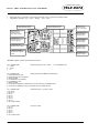
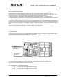
NSI12-02 - NMEA - SYNCHRO Interface board - USER MANUAL NSI12–02 NMEA - SYNCHRO Interface board USER MANUAL NSI12–02 NMEA - SYNCHRO Interface board is a conversion unit from digital data on serial line to 2 analog signals in synchro format on independent or correlated channels. Multiple operative modes: by means of dip-switches different NMEA sentences and Synchro gear ratio can be selected. A bright display with operative and diagnostic functions is present. Voltages presence luminous signalling. The device is microController managed. Analog/Digital/Serial line galvanic insulation, especially suited for on-board installation. TELE DATA S.r.l. Via Vincinella 14 - 19035 - S.Stefano M. (SP) Tel. 0187-632323 Fax 0187-631060 www.tele-data.it Email: [email protected] Pag. 1 di 8 NSI12-02 - NMEA - SYNCHRO Interface board - USER MANUAL Board dimensions: 230x120mm, Components max height: 26mm, Connectors max height: 30mm Temperature: Operating 0°C ÷ +50°C - Storage - 10°C ÷ +60°C Light signalling for internal positive electrical supply Light signalling for internal negative electrical supply Connector JX4 Serial line RS422 - NMEA line input - STATUS line output Light signalling for external positive electrical supply Jumper JP4 RS422 line termination resistor plugging in Light signalling for external negative electrical supply Dip-Switch S1 Operative modes selector Connector JX1 – Reference input / Synchro1 output Display to visualize operative and diagnostic notices Connector JX3 – Synchro 2 output TERMINAL PINOUT (5,08mm pitch terminal Connectors) JX2 CONNECTOR: 1- +13Vdc 2- -13Vdc 3- 0V Electrical supply ±12÷18V, 1Amax - 1,3A Resettable fuses JX4 CONNECTOR: RS422 serial line (see NMEA line termination) 1- Output STATUS line True 2- Output STATUS line Complement 3- Serial line GND 4- Input NMEA line Complement 5- Input NMEA line True 6- Serial line GND 7- Connection to NMEA line Complement (to connect the line to an additional user) 8- Connection to NMEA line True (to connect the line to an additional user) JX1 CONNECTOR: 1- R1 / RH in 2- R2 / RL in 3- R1 out 4- R2 out 5- S1 out 6- S2 out 7- S3 out 8- S4 out (NOT used) References input / Synchro 1 output JX3 CONNECTOR: 1- R1 out 2- R2 out 3- S1 out 4- S2 out 5- S3 out 6- S4 out (NOT used) Synchro 2 output Pag. 2 di 8 Connector JX2 – Electrical supply ±12 ÷ ±18V input NSI12-02 - NMEA - SYNCHRO Interface board - USER MANUAL ELECTRICAL SUPPLY The unit needs a dual voltage with range from 12Vdc to 18Vdc, also non stabilised. Two leds indicate the external power supplies presence. Maximum consumption is 1A. Two 1,3A resettable fuses are present. Specified supplies are produced and stabilised locally. Two leds indicate the internal ±5V voltages presence. Micro controller circuitry is galvanically isolated for maximum electrical noise immunity. RS422 serial line circuitry (each line) is galvanically isolated for maximum electrical noise immunity. NMEA INPUT RS422 optoinsulated serial line – MNEA 0183 Protocol (IEC 61162-1) Messages - baud rate 38400, 8bit/data, No parity, 1bit stop. $--HDT,x.x,T*hh<CR><LF> Heading, Degrees True Converted data: Heading = Course $--XDR,A,xx.xx,D,R,A,xx.xx,D,P,*hh<CR><LF> $--XDR,A,-xx.xx,D,R,A,-xx.xx,D,P,*hh<CR><LF> negative values (anticlockwise) A: Angular displacement, D: Degree, R: Roll, P: Pitch Converted data: Roll, Pitch Messages - baud rate 4800, 8bit/data, No parity, 1bit stop. $--VBW,y.y,x.x,Y,z.z,x.x,Z,x.x,A,x.x,A*hh<CR><LF> $--VBW,-y.y,x.x,Y,-z.z,x.x,Z,x.x,A,x.x,A*hh<CR><LF> negative values (astern) y.y = Longitudinal water-referenced speed data, Knots, Y=A: data valid, Y=V: data invalid. z.z = Longitudinal ground-referenced speed data, Knots, Z=A: data valid, Z=V: data invalid. VBW - Water-referenced and ground-referenced speed data. Converted data: Speed. NMEA LINE TERMINATION Near the connector JX4 a two pins header is present (JP4) which, when shunted, inserts on the RS422 input serial line a termination resistor. To be applied if the device is the unique or the last user in the transmission line. SELECTABLE OPERATIVE MODES Operate dipswitch to set different operative modes as shown in the table below Dip - switch Nr. NMEA message Converted data Synchro Gear ratio Display notice 1 2 3 4 Channel 1 Channel 2 1 off off off off HDT Course 1x 36x ----heading_1_36_ 2 on off off off XDR Roll 2x 36x ----roll_2_36_ 3 off on off off XDR Pitch 2x 36x ----pitch_2_36_ 4 on on off off XDR Roll 1x 36x ----roll_1_36_ 5 off off on off XDR Pitch 1x 36x ----pitch_1_36_ 6 on off on off HDT Course 1x 1x ----heading_1_1 7 off on on off VBW Speed Water-referenced 120 Knots/revolution Ground-referenced 120 Knots/revolution Pag. ----speed_120_120g 3 di 8 NSI12-02 - NMEA - SYNCHRO Interface board - USER MANUAL ELECTRICAL SUPPLY The unit needs a dual voltage with range from 12Vdc to 18Vdc, also non stabilised. Two leds indicate the external power supplies presence. Maximum consumption is 1A. Two 1,3A resettable fuses are present. Specified supplies are produced and stabilised locally. Two leds indicate the internal ±5V voltages presence. Micro controller circuitry is galvanically isolated for maximum electrical noise immunity. RS422 serial line circuitry (each line) is galvanically isolated for maximum electrical noise immunity. NMEA INPUT RS422 optoinsulated serial line – MNEA 0183 Protocol (IEC 61162-1) Messages - baud rate 38400, 8bit/data, No parity, 1bit stop. $--HDT,x.x,T*hh<CR><LF> Heading, Degrees True Converted data: Heading = Course $--XDR,A,xx.xx,D,R,A,xx.xx,D,P,*hh<CR><LF> $--XDR,A,-xx.xx,D,R,A,-xx.xx,D,P,*hh<CR><LF> negative values (anticlockwise) A: Angular displacement, D: Degree, R: Roll, P: Pitch Converted data: Roll, Pitch Messages - baud rate 4800, 8bit/data, No parity, 1bit stop. $--VBW,y.y,x.x,Y,z.z,x.x,Z,x.x,A,x.x,A*hh<CR><LF> $--VBW,-y.y,x.x,Y,-z.z,x.x,Z,x.x,A,x.x,A*hh<CR><LF> negative values (astern) y.y = Longitudinal water-referenced speed data, Knots, Y=A: data valid, Y=V: data invalid. z.z = Longitudinal ground-referenced speed data, Knots, Z=A: data valid, Z=V: data invalid. VBW - Water-referenced and ground-referenced speed data. Converted data: Speed. NMEA LINE TERMINATION Near the connector JX4 a two pins header is present (JP4) which, when shunted, inserts on the RS422 input serial line a termination resistor. To be applied if the device is the unique or the last user in the transmission line. SELECTABLE OPERATIVE MODES Operate dipswitch to set different operative modes as shown in the table below Dip - switch Nr. NMEA message Converted data Synchro Gear ratio Display notice 1 2 3 4 Channel 1 Channel 2 1 off off off off HDT Course 1x 36x ----heading_1_36_ 2 on off off off XDR Roll 2x 36x ----roll_2_36_ 3 off on off off XDR Pitch 2x 36x ----pitch_2_36_ 4 on on off off XDR Roll 1x 36x ----roll_1_36_ 5 off off on off XDR Pitch 1x 36x ----pitch_1_36_ 6 on off on off HDT Course 1x 1x ----heading_1_1 7 off on on off VBW Speed Water-referenced 120 Knots/revolution Ground-referenced 120 Knots/revolution Pag. ----speed_120_120g 3 di 8 NSI12-02 - NMEA - SYNCHRO Interface board - USER MANUAL DISPLAY A bright display with operative and diagnostic functions is present: it shows scrolling writings indicating conversion type and possible anomalies, as the absence or the invalidity of the NMEA sentence or the reference signals absence. Display timing is about 2Hz with a duty cycle of 2/3 ON and 1/3 OFF so the visualisation seem to be a flashing that helps to distinguish the letters. In order to well interpret the notice synchronise attention to the visualisation of the initials dashes of writing that appear as 4 flashes of the middle line, then in sequence take the following letters shown to compose the notice. In standard operative mode, i.e. with NMEA message present, recognised and valid, and with the reference signals present, only the conversion transport notice is displayed (see table) In case of anomaly is also displayed the written FAULT and the written MGS OFF in case of fault message and REF OFF in case of references lack or both. In case of Local Control mode the written LOCAL and the conversion transport notice are displayed and REF OFF if references lack. SYNCHRO OUTPUT There are two independent synchro channels. R Signals: 115V(±10%) / 400Hz(±15%) external references with insulation transformer. Made available in output with a 0,5A Resettable fuse on R1 line of both outputs. S Signals: 90Vll Rms. / 400Hz. - Protected against short circuit and overload. Signals derives from the input R References, so are frequency and amplitude dependent. Accuracy: ±8 min. for each channel vs. 360° range. Power: 2VA each channel. OUTPUT “STATUS REPORT” On the out channel of the serial line which has the NMEA sentence as input, and therefore with the same electrical parameters, (RS422, baud rate, etc.) an ASCII message, in VT100 mode, is sent to indicate the unit conditions: the selected operative mode, presence and acknowledgement of the input message, presence of the reference signal RH-RL for the synchro outputs, angular data (on 360° range) for either synchro channels. This message has diagnostic usability, to employ with any terminal emulator program. The following information are displayed: type of NMEA message to be recognized input / synchro outputs gear ratio transport type current operating status NMEA message effectiveness status references presence status output angles of the 2 synchro channels on 360° range (that is, without regard to the transport) Examples: -------------------------------------------------- NMEA interface -NMEA sentence input: HDT Synchro outputs: HEADING 2 speeds 1x / 36x Status: OPERATIVE NMEA sentence: Present, recognized, valid Synchro reference signal: ON \ ANGLE out1: 119.06 out2: 326.34 -------------------------------------------------- NMEA interface -NMEA sentence input: HDT Synchro outputs: HEADING 2 speeds 1x / 36x Status: NOT OPERATIVE, output disabled NMEA sentence: NOT PRESENT Synchro reference signal: ON / ANGLE out1: 032.77 out2: 099.90 ------------------------------------------------- Pag. 4 di 8 NSI12-02 - NMEA - SYNCHRO Interface board - USER MANUAL References anomaly The unit verifies the presence of the reference signals and, in case of absence, indicates the fault (OFF). In this case the current status becomes: NOT OPERATING, output disabled Synchro outputs are disabled. NMEA messages anomaly - If the unit detects the NMEA message as valid the notice (NMEA sentence) is: Present, Recognized, valid If there isn’t references anomaly, the state is operating with normal operation. - If the computer detects the NMEA message, but it isn’t valid (checksum error, wrong fields) the notice is: Present, Recognized, NOT VALID The status of the unit is not operating, the synchro outputs are disabled. - If the computer detects a message with NMEA header, but it isn’t the wanted one the notice is: Present, NOT RECOGNIZED The status of the unit is not operating, the outputs are disabled. - If the unit does not recognize any message with NMEA header. the notice is: NOT PRESENT The status of the unit is not operating, the outputs are disabled. - If the unit is in Local Control, the notice (NMEA sentence) is: NOT CHECKED The status of the unit is: LOCAL CONTROL. Synchro outputs are controlled by menu commands. DIGITAL TO ANALOG CONVERSION When the NMEA message is received, recognized and validated, the data is extracted and processed and 2 angles are obtained to carry out in synchro format on the two channels. There are three procedures for the conversion of the numerical data into analogue signal: computing, theoretical data reading, calibration data reading. - Computing: For each angle the microprocessor calculates the sine and cosine values. These two values are inserted in two D/A converters that modulate in amplitude a signal derived from the references RH-RL coming from external devices. The obtained signals are amplified and applied to two transformers in SCOTT configuration implementing a Resolver to Synchro conversion and an elevation in voltage to 90Vll. The conversion from angle to sine and cosine data involves trigonometric calculations that are quite heavy and occupy a certain time interval. - Theoretical data reading: to speed the response time the calculation results for all angles were included in a non-volatile memory, so that with the angle value, there is a memory access for reading the related sine and cosine values. The memory reading is faster than the calculations execution and using this procedure reduces the time conversion. Using theoretical trigonometric values the accuracy of the overall output signal depends on the hardware used: linearity, accuracy and precision of D/A converters, amplifiers, calibration resistors, transformers. - Calibration data reading: to improve synchro signal accuracy, during production process, a calibration phase is accomplished: using a precision synchro measuring instrument as reading feedback, for each theoretical angle sine and cosine values are stored related to the actual angle which in output provides, through the chain of hardware, the desired signal with the maximum possible precision. The procedure is performed for each of the two channels. The data obtained are stored in a nonvolatile memory. At power-on electronics performs a presence check for stored data: calibration data are used for maximum precision and speed, if calibration data are not present the stored theoretical data are used, if also theoretical data are not present trigonometric calculations are performed every time. LATENCY TIME The latency time is defined as the interval between the end of transmission of the input data on the serial line (which depends by the transmitter) and the updating of the synchro signal output. The input message is received, recognized and validated, the data is extracted, standardised and processed and then converted and applied on the output channels. The board has two synchro output channels: channel 1 and channel 2. On channel 1 signal is transmitted with coarse gear ratio transport 1x or 2x. On channel 2 signal is transmitted with fine gear ratio transport 36x. (With operating mode Heading_1_1 on both channels signal is transmitted 1x). (With operating mode VBW package recognition on channel 1 is transmitted the speed data referred to the water and channel 2 is transmitted speed data referred to ground, both with 120knots/rev transport). The unit first updates the channel 2 signal (fine), and then the channel 1 signal (coarse). The latency time of channel 2 is 1.5 msec. The latency time of channel 1 is 2.4 msec (0.9 msec after channel 2). Pag. 5 di 8 NSI12-02 - NMEA - SYNCHRO Interface board - USER MANUAL DOUBLE SPEED SYNCHRO USERS During a period of 0.9 msec, the overall output data is composed by a fine updated signal and by a coarse signal belonging to the immediately preceding data transmission (valid). With a maximum accepted coarse/fine misalignment within 1°, with a 10Hz transmission frequency, the turn rate or roll or pitch motion will be 10°/sec. (Relatively high) (As the transmission frequency increase the situation is better). Under this speed rate, in the situation described, for double speed users, updating only the fine signal results in a substantial correctness of the overall output, thanks to the course/fine correction performed by these systems. This means the correctness of the overall signal in double speed system in the period of 0.9 msec. between the fine signal and coarse signal updating. Updating coarse data the overall signal will be also consistent. By virtue of the arguments exposed above: The latency time for double speed synchro users is considered to be the fine channel one: 1.5 msec. The latency time for single speed (coarse) synchro users is considered the coarse channel one: 2.4 msec. (Note) In systems with 1x / 36x double speed coarse signal transmits information on an angular range of 360°, while the fine signal transmits information on an angular range of 10° (360/36). The coarse signal task is identifying one of the 36 sectors of 10 degrees in which to apply the detailed information of the fine signal. The error of the coarse signal in modulo 10° related to the fine one can be ± 5° maximum. Exceeding this threshold in a direction corresponds to the transition to the opposite limit (from + 5° to + 5.1° is equivalent to -4.9° in the 10° adjacent area). The only critical situation is when the misalignment is exactly +5° (= -5 °) because it is not possible to identify uniquely the sector, having two adjacent sectors the same error in absolute value: | +5 | = | -5 |. Example. Coarse signal 30°, fine signal 5°: the overall signal can be equally both 35° that 25°. For any other error value the correction is made in the direction of the minor error in absolute value: if error is +4.9, corresponding to -5.1, the correction works in the sense of +4.9 error and not -5.1. With an efficient coarse/fine system correction the misalignment between the two channels can then be up to ± 4.9° (depends on the resolution of the system in the reading of the two channels). Of course, it’s better that the system operates with the best alignment between the two channels, that is, with the best accuracy possible for the coarse signal. If the user is a single speed one, it only uses the coarse signal so it’s essential that this signal has the best possible accuracy. MEASURED LATENCY TIMES HDT sentence - 20Hz - SW P56-005-07.00 1x – 36x outputs Time1 = channel 2 latency time Time 2 = channel 1 latency time – channel 2 latency time = Time between the channel 2 updating and the channel 1 updating LATENCY TIME MEMORY PRESENT DATA Channel 1 Calibration NO NO NO NO YES YES YES YES Channel 2 Calibration NO NO YES YES NO NO YES YES Theoretical data NO YES NO YES NO YES NO YES NMEA data elaboration = 0,6ms Trigonometric calculations = 2,4ms Theoretical data memory reading = 0,6ms Calibration data memory reading = 0,8ms Pag. 6 di 8 TIMES IN millisec. TIME 1 TIME 2 3,0 1,2 1,4 1,4 3,0 1,2 1,4 1,4 2,4 0,6 2,4 0,6 0,8 0,8 0,8 0,8 Notes Only computing both channels Stored theoretical data both channels Stored calibration data both channels NSI12-02 - NMEA - SYNCHRO Interface board - USER MANUAL NMEA TRANSMISSION FREQUENCY Maximum duration of the HDT message with hundreds, tens, units, comma, tenths, hundredths, thousandths: 5,46msec. Maximum duration of the XDR message with negative rolling and pitch data: minus sign, hundreds, tens, units, comma, tenths, hundredths, thousandths: 10,4msec (transmissions without delays between one character and another). If on the serial line only the HDT message is transmitted the maximum transmission frequency is 1 / 0.00546 = 183 Hz. If on the serial line only the XDR message is transmitted the maximum transmission frequency is 1 / 0.0104 = 96 Hz. If multiple messages are transmitted on the serial line, maximum transmission frequency of the selected data will be lower and depending on the specific case. In management software of the conversion board in object the processing of the received and validated data, and the receipt and recognition of further data on the serial line are independent processes that can co-exist, for which it can receive and recognize data packets on the serial line also before it has validated, processed, converted and updated on the output signals the last received data. So the only limit of the transmission frequency is the time occupation on the input serial line. The unit has been verified with proper operation in receiving condition of HDT message up to 175Hz frequency transmission. LOCAL OPERATION On the unit a service line used for local control during calibration and testing is present. It’s to use with a terminal emulator program. The unit transmits and receives messages in ASCII code, in VT100 mode. Service line electric format RS232C, baud rate 38400, 8bit / data, No parity, 1 bit stop. Jumper JP5 Connect 2-3 to enable the Service line Connector JX6 Service RS232 Serial line The connector JX6 is NOT present: you must mount it or provide an appropriate connections with the relative pads. Jumper JP5 pin 2-3 must be connected to enable the Service line JX6 CONNECTOR: Service RS232C Serial line 1- TX ----- to connect to pin 2 of PC DB9 male RS232 connector 2- RX ----- to connect to pin 3 of PC DB9 male RS232 connector 3- GND ----- to connect to pin 5 of PC DB9 male RS232 connector Pag. 7 di 8