1
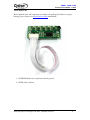
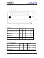
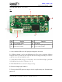
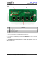
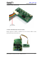
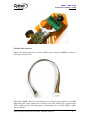
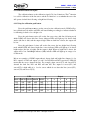
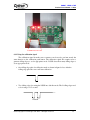
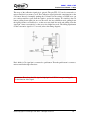
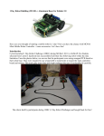
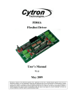
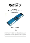
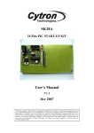
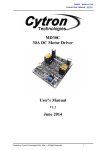
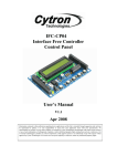
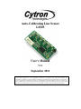
Auto-Calibrating Line Sensor
LSS05
User’s Manual
V1.2
September 2011
Information contained in this publication regarding device applications and the like is intended through suggestion only and may
be superseded by updates. It is your responsibility to ensure that your application meets with your specifications. No
representation or warranty is given and no liability is assumed by Cytron Technologies Incorporated with respect to the accuracy
or use of such information or infringement of patents or other intellectual property rights arising from such use or otherwise. Use
of Cytron Technologies’s products as critical components in life support systems is not authorized except with express written
approval by Cytron Technologies. No licenses are conveyed, implicitly or otherwise, under any intellectual property rights.
ROBOT . HEAD to TOE
Product User’s Manual – LSS05
Index
1. Introduction and Overview
3
2. Packing List
4
3. Product Specification and Limitations
5
4. Board or Product Layout
6
5. Installation (hardware)
8
6. Getting Started (from user get the item until using it)
13
7. Warranty (6 months or 1 year)
17
Created by Cytron Technologies Sdn. Bhd. – All Rights Reserved
2
ROBOT . HEAD to TOE
Product User’s Manual – LSS05
1. INTRODUCTION AND OVERVIEW
LSS05 (Low cost line sensor bar) consists of 5 IR transmitter and IR receiver pairs.
LSS05 is the typically used for embedded system or robots in line following task. LSS05 can
be used for either dark or bright line following. Any color with distinct brightness difference
is suitable for LSS05.
The IR transmitters on LSS05 are pulsed to allow the transmitter to off at certain idle
period of sensor. This is to minimize the current consumption of LSS05 to at least half of the
current consumption compared to a normal unregulated IR line sensor. Power polarity
protection is available on LSS05 in case the user accidently applies a reverse voltage.
LSS05 have 5 digital outputs to user indicating the existence of the line. The
threshold to the brightness of line existence will be set when the user calibrate the sensor to
the surface that it will recognize. One digital input of calibration signal is available to user for
automated calibration function by the user system. User can pull down this signal line with
microcontroller to calibrate the sensors. This signal line also can be use to enter different
mode of LSS05. Each sensor of the 5 sensors on LSS05 is independent of each other. The
refreshing rate of the sensors is more than 100Hz. Every sensor is provided with its own
LEDs as indication of line detection.
LSS05 has a manual calibration button. The calibration button is multifunctional.
User can enter different mode of functions using calibration button too as the alternative to
the calibration signal.
Note: Red color is very bright to IR sensor, thus LSS05 has difficulties in red – white pair
color line follow.
Created by Cytron Technologies Sdn. Bhd. – All Rights Reserved
3
ROBOT . HEAD to TOE
Product User’s Manual – LSS05
2. PACKING LIST
Please check the parts and components according to the packing list. If there is any part
missing, please contact us at [email protected] immediately.
1. LSS05 PCB with every component soldered properly.
2. LSS05 cable connector
Created by Cytron Technologies Sdn. Bhd. – All Rights Reserved
4
ROBOT . HEAD to TOE
Product User’s Manual – LSS05
3. PRODUCT SPECIFICATION AND LIMITATIONS
Dimensions
Specifications
Parameter
Min
Typical Maximum
IR Emission (peak wavelength)
Unit
940
nm
Input signal, VIH
2
5
V
Input signal, VIL
0
0.8
V
5
V
Output Signal
Absolute Maximum Rating
Parameter
Typical
Maximum
Unit
Operating voltage
5
V
Maximum Current (I/O signal pins)
20
mA
4
cm
Sensing distance
Minimum
1
2
Created by Cytron Technologies Sdn. Bhd. – All Rights Reserved
5
ROBOT . HEAD to TOE
Product User’s Manual – LSS05
4. BOARD OR PRODUCT LAYOUT
A
Top
B
C
F
D
E
Label
Function
Label
Function
A
Sensor indicator LEDs
D
PIC16F819
B
Calibration button
E
Power and output signal connector
C
Mode indicator LED
F
Power indicator LED
A – Sensor indicator LEDs (red) will light up showing that it detects line.
B – Calibration button is used to enter different modes. Press once to enter the calibration
mode. Press twice to set the line sensor bar into dark line following mode and press 3 times to
set the line sensor bar into bright line mode.
C – Mode indicator LED (orange) is for indication of the mode. LED will light up if LSS05
is in bright line detection mode. Otherwise, it is off.
D – PIC16F819 PIC microcontroller for data processing.
E – Power and output signal connector
F – Power indicator LED (green) showing the board is supplied with power. Maximum input
power is 5V.
Created by Cytron Technologies Sdn. Bhd. – All Rights Reserved
6
ROBOT . HEAD to TOE
Product User’s Manual – LSS05
Bottom
C
B
A
Label
Function
A
Pairs of IR sensor
B
Manufacturing Test Points
C
Input/output signal label
A – Pairs of IR sensor which consist IR transmitter and IR receiver.
B – It is reserved for Manufacturing Test Point. Please DO NOT short or connect wire to any
of these pins.
C –Input/output signal label showing the Power (5V, GND), output signal pins (O1-O5) and
calibration signal (Cal.).
Created by Cytron Technologies Sdn. Bhd. – All Rights Reserved
7
ROBOT . HEAD to TOE
Product User’s Manual – LSS05
5. INSTALLATION (HARDWARE)
Connect to
microcontroller
5.1 LSS05 to Mini Mobile Robot Controller (MC40A)
Example application of LSS05 is in MC40A. Used as line detection, LSS05 is usually
mounted at the bottom of the mobile robot.
Created by Cytron Technologies Sdn. Bhd. – All Rights Reserved
8
ROBOT . HEAD to TOE
Product User’s Manual – LSS05
5.1LSS05 cable connector
Figure below shown cable used to connect LSS05 to microcontroller. 2020H-08 connector is
used at the end of the cable.
Pin pitch for 2020H connector is not standard size for donut board pin pitch. To use LSS05
with donut board, simply cut the end of connector and solder another type of connector like
2510 or 3960 connector. Following figure is showing the step to connect LSS05 to others
type of connector.
Created by Cytron Technologies Sdn. Bhd. – All Rights Reserved
9
ROBOT . HEAD to TOE
Product User’s Manual – LSS05
1
2
3
4
Created by Cytron Technologies Sdn. Bhd. – All Rights Reserved
10
ROBOT . HEAD to TOE
Product User’s Manual – LSS05
5
6
7
Created by Cytron Technologies Sdn. Bhd. – All Rights Reserved
11
ROBOT . HEAD to TOE
Product User’s Manual – LSS05
Figure below shown LSS05 was connected to donut board.
Created by Cytron Technologies Sdn. Bhd. – All Rights Reserved
12
ROBOT . HEAD to TOE
Product User’s Manual – LSS05
6. GETTING STARTED
LSS05 need to be calibrated to retrieve the dark and bright value of the surface that it
will do the line follow. Every of the IR sensor pairs need to be exposed to the dark and bright
surface for it to read the value and save it. LSS05 will save the value in EEPROM, it will
retrieve back the data from the EEPROM every time its switch on. Hence, only one time
calibration is needed for the same surface and line. To calibrate LSS05, simply press the
calibration push button once or pulling down the Cal. for few milliseconds. Calibration will
be start by exposing the sensor to the bright surface and then to the dark surface as indicated
by the LEDs. 3 LEDs blinking means the bright calibration (2.5 seconds) and 2 LED blinking
means the dark calibration (2.5 seconds). Calibration is normally done by crossing every
sensor across the line that it will follow as shown in the figure below. Sensors will save the
brightest value in the bright calibration process and darkest value in dark calibration. User
can calibrate by simply swinging the sensors across the dark and bright surface in order to
expose every sensor to the dark and bright surface. Calibration of every sensor is
independent and value of each sensor will be saved.
Example motions of calibration by crossing the sensor between the lines.
Created by Cytron Technologies Sdn. Bhd. – All Rights Reserved
13
ROBOT . HEAD to TOE
Product User’s Manual – LSS05
6.1 Calibration button and signal.
The calibration button or the calibration signal (Cal.) has 2 functions. The 1st function
is to call for calibration of the line sensor and the 2nd function is to set whether the sensor bar
will operate for dark line following or bright line following.
6.1.1 Using the calibration push button
Press the push button once to set the sensor bar into calibration mode. LSS05 will go
into calibration mode and the red LEDs will start blinking accordingly to indicate whether it
is calibrating for dark color or bright color.
Press the push button twice will set the line sensor into dark line following mode
which LSS05 will detect dark line. Sensor indicator LEDs will light up if it detects dark
surface (the line is dark) and the output is high. When no dark line is detect, the output will
be low.
Press the push button 3 times will set the line sensor bar into bright line following
mode which LSS05 will detect bright line; sensor indicator LEDs will light up if it detects
bright surface (the line is bright) and the output is high. When no bright line is detect, the
output will be low. Dark/Bright indicator (D/B) indicator LED will light up in orange color
for this mode.
Below are examples of LSS05 output when it detects dark and bright line. Output 1 is for
DS1, output 2 for DS2 and output 3,4, and 5 for DS3,DS4 and DS5 respectively. LED ON
means that the sensor detected the line. For example, when sensor1(U1) and sensor2(U2)
detected the dark line, DS1 and DS2 will turn ON. The output for sensor1(U1) and
sensor2(U2) is high while it is low for sensor which do not detect the line (sensor3(U3),
sensor 4(U4) and sensor 5(U5)).
LED
Output
DS1/U1 DS2/U2 DS3/U3 DS4/U4 DS5/U5
1
2
3
4
5
ON
ON
OFF
OFF
OFF
1
1
0
0
0
OFF
ON
ON
ON
OFF
0
1
1
1
0
OFF
OFF
OFF
ON
ON
0
0
0
1
1
OFF
OFF
OFF
OFF
OFF
0
0
0
0
0
Created by Cytron Technologies Sdn. Bhd. – All Rights Reserved
14
ROBOT . HEAD to TOE
Product User’s Manual – LSS05
5V GND 01 02 03 04 05 Cal
6.1.2 Using the calibration signal
The calibration signal from the sensor connector can be used to perform exactly the
same function as the calibration push button. The calibration signal line requires user to
generate falling edges to set for appropriate mode. LSS05 detect how many falling edges to
set to appropriate mode.
•
One falling edge pulse for calibration mode as shown in figure below. After the
falling edge pulse the sensor will start calibration.
•
Two falling edges for setting the LSS05 into dark line mode. The 2 falling edges need
to be in range of 1.5 seconds.
1.5s
Created by Cytron Technologies Sdn. Bhd. – All Rights Reserved
15
ROBOT . HEAD to TOE
Product User’s Manual – LSS05
The usage of the calibration signal pin is optional. The pin (TTL, 5V) can be connected to a
microcontroller if user want to use it. The Calibration signal pin has the same functions as the
Cal button. Instead of manually pushing the Cal button for the settings of LSS05, user can
use a microcontroller to pull down the signal to get into the settings. It is similar to the Cal
button, pulling down signal pin once set the sensor bar into calibration mode, pulling down
the signal pin twice consecutively to set the sensor into dark line mode and pulling down the
signal pin 3 times consecutively set the sensor into bright line mode. The timing requirement
for the consecutive signals is 1.5 seconds (refer to the timing diagram).
Pin 8 which is Cal signal pin is connected to push button. Then the push button is connect to
microcontroller through a transistor.
Reminder: Please keep the Cal. signal at high logic level 5V if it’s not generating pulse
for the function of the signal.
Created by Cytron Technologies Sdn. Bhd. – All Rights Reserved
16
ROBOT . HEAD to TOE
Product User’s Manual – LSS05
8. WARRANTY
Product warranty is valid for 6 months.
Warranty only applies to manufacturing defect.
Damage caused by misuse is not covered under warranty.
Warranty does not cover freight cost for both ways.
Prepared by
Cytron Technologies Sdn. Bhd.
19, Jalan Kebudayaan 1A,
Taman Universiti,
81300 Skudai,
Johor, Malaysia.
Tel:
Fax:
+607-521 3178
+607-521 1861
URL: www.cytron.com.my
Email: [email protected]
[email protected]
Created by Cytron Technologies Sdn. Bhd. – All Rights Reserved
17