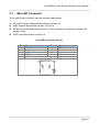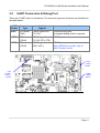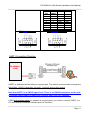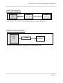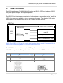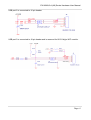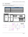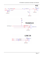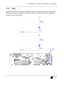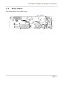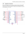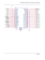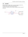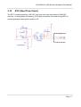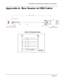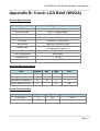
1
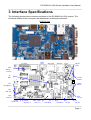
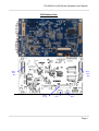
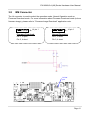
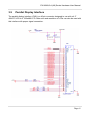
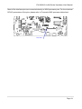
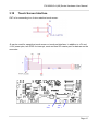
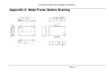
EX-9686U/A-L(A9)
Hardware User Manual
EX-9686U/A-L(A9) Series Hardware User Manual
Release Notes
Version
Release Date
Notes
1.00
2.00
November, 2013
January, 2014
Initial Release
The 2nd release
Disclaimer
This documentation is provided for use with TOPSCCC Technology CO., LTD products. No
license to TOPSCCC Technology CO., LTD property rights is granted. TOPSCCC
Technology CO., LTD assumes no liability and provides no warranty either expressed or
implied relating to the usage or intellectual property right infringement that may result from
its use.
TOPSCCC provides this document “as is,” without warranty of any kind, expressed or
implied, including, but not limited to, its particular purpose. TOPSCCC Technology CO.,
LTD may make changes to this document without notice.
Page 2
EX-9686U/A-L(A9) Series Hardware User Manual
Table of Contents
TABLE OF CONTENTS........................................................................................... 3
1
PRECAUTIONS ............................................................................................... 4
1.1
1.2
1.3
2
PRODUCT FEATURES..................................................................................... 6
2.1
2.2
3
Safety Precautions.........................................................................................4
Write Prohibited Regions ................................................................................5
Warranty .......................................................................................................5
Overview.......................................................................................................6
Features and Specifications ............................................................................7
INTERFACE SPECIFICATIONS ......................................................................... 8
3.1
3.2
3.3
3.4
3.5
3.6
3.7
3.8
3.9
3.10
3.11
3.12
3.13
3.14
3.15
MicroSD Connector...................................................................................... 10
UART Connectors & Debug Port ................................................................... 11
USB Connectors .......................................................................................... 14
Audio Interface ............................................................................................ 16
Ethernet Interface ........................................................................................ 18
Power Supply (DC-IN connector)................................................................... 19
GPIO Pin Header......................................................................................... 20
BM Connector ............................................................................................. 22
Parallel Display Interface .............................................................................. 23
Touch Screen Interface............................................................................... 25
LED .......................................................................................................... 26
Reset Switch ............................................................................................. 27
Expansion Connector ................................................................................. 28
EEPROM .................................................................................................. 30
RTC (Real Time Clock)............................................................................... 31
APPENDIX A: BOX HEADER TO DB9 CABLE........................................................ 32
APPENDIX B: 5-INCH LCD BRIEF (WVGA) ............................................................ 33
APPENDIX C: METAL FRAME OUTLINE DRAWING ............................................... 34
Page 3
EX-9686U/A-L(A9) Series Hardware User Manual
1 Precautions
1.1
Safety Precautions
In order to use this product safely, please take special note of the following precautions.
•
Read all product manuals and related documentation before using this product. Use
this product correctly and safely. Follow all warnings.
•
If operating or extending this product in a manner not described in this manual,
please do so at your own risk. Be sure to fully read this manual and other technical
information on our website and proceed safely and responsibly.
•
Do not install this product in a place with a lot of water, moisture, dust or soot. This
could cause product failure, fire, or an electric shock.
•
Some parts of this product generate heat and can reach high temperatures. This
may cause burns if it is improperly handled. Do not touch the electronic components
or surrounding area while powered on or immediately after being turned off.
•
Carry out any design and development only after you have thoroughly read and
understood this manual and any other related technical materials on the website or
in the data sheets. Test your product thoroughly for reliability and safety.
•
This product is not intended for applications that require extremely high reliability,
safety, functionality and accuracy: including but not limited to medical equipment,
traffic control systems, combustion control systems, and safety equipment. This
company is not liable for death or injury if used in such systems.
•
This product uses semiconductor components designed for generic electronics
equipment such as office automation, communications, measurement equipment
and machine tools. Foreign noise or a power surge may cause this product to
malfunction or fail.
•
To ensure there is no risk of bodily harm or property damage, be sure to take all
electrical safety precautions such as protection circuits, limit switches, fuse breakers,
or redundant systems. Only use the device after sufficient reliability and safety
measures are in place.
Page 4
EX-9686U/A-L(A9) Series Hardware User Manual
1.2
Write Prohibited Regions
Data stored by the EEPROM, i.MX6Q/D electrical fuse (e-Fuse) is used by the software
contained in this product. Do not write to these regions as this may cause the product
stop working correctly. Purposely writing to these regions voids the product warranty.
1.3
Warranty
As described in the Product Warranty Policy provided with this product, the main board is
covered by a one year replacement warranty starting from the time of purchase. Please
note that the other included goods and software are not covered under this warranty. Some
knowledge used by TOPSCCC Technology CO., LTD is provided by third parties, and
TOPSCCC Technology CO., LTD. makes no representation or warranty as to the accuracy
of such information.
Page 5
EX-9686U/A-L(A9) Series Hardware User Manual
2 Product Features
2.1
Overview
The EX-9686U/A-L(A9) is a Freescale iMX6 ARM Cortex-A9 based embedded for Gigabit
Ethernet ; Micro SD card socket ; USB 2.0 host connector x2 ; USB 2.0 OTG connector x1 ;
RS232 x1 and RS485x1 ; GPIO (8-bit) ; IEEE 802.11 b/g/n Wi-Fi x 1(Optional) . It is a
flexible, high performance and inexpensive platform designed for embedded applications
such as communication/ home/ building/ factory automation.
Each device can be installed in advance with Windows Embedded Compact 7, Ubuntu
11.10 or Android 4.2 for immediate evaluation.
Page 6
EX-9686U/A-L(A9) Series Hardware User Manual
2.2
z
z
z
z
z
z
z
z
z
z
z
z
z
z
z
Features and Specifications
Freescale iMX6 ARM Cortex™-A9 single core @ 1 GHz (iMX6 Solo)
1GB DDR3 SDRAM
4GB eMMC Flash
Hardware Video Decoder Support
10/100/1000 Mbps Gigabit Ethernet interface RJ-45 connector x1
Single parallel 24-bit display port(TTL LCD) x1(Internal)
Resistive/ Capacitive touch port x1(Internal)
+5V DC power input connector x1
USB 2.0 host connector x2
USB 2.0 OTG connector x1
Micro SD card socket x1
SGTL5000 Audio Codec , Amplifier circuit
MIC-in connector x1(Internal), Earphone connector x1(internal)
Speaker connector x2 (L/R)
DB9 connector x2 (RS232 x1 and RS485x1)
z Debug (Console) Port: 8-pin header x1 (optional debug cable is required)
z GPIO (8-bit) pin header x1(Internal)
z IEEE 802.11 b/g/n Wi-Fi x 1 (Optional)
z PCB Dimension: 72mm x 120mm
Page 7
EX-9686U/A-L(A9) Series Hardware User Manual
3 Interface Specifications
The following photos show connector positions on the EX-9686U/A-L(A9) product. The
functional details of the connectors are described in subsequent sections.
PCB Top View
USB
OTG
J1: GPIO
MicroSD
Ethernet
Reset
D6/D7:
LED
CN2:
Debug /
Console
J4:
BM
CON3:
RS485
CON4:
RS232
JP1:
Headphone
JP3:
MIC-IN
JP2:
Line-IN
JP4:
5V-out
CON1:
Speaker R
CON2:
Speaker L
CN5: USB
Host x 2
J6:
USB Host
J8:
USB Host
J7:
DC-IN
J5:
DC-IN
Page 8
EX-9686U/A-L(A9) Series Hardware User Manual
PCB Bottom View
HC1:
EXT
Bus
HC2:
EXT
Bus
CN6:
LCD
J9:
CTP
CN7:
RTP
Page 9
EX-9686U/A-L(A9) Series Hardware User Manual
3.1
MicroSD Connector
The microSD host connector has the following specification:
z
z
z
z
SD Host Controller Standard Specification version 3.0
MMC System Specification version 4.2/4.3/4.4
SD Memory Card Specification version 3.0 and supports the Extended Capacity SD
Memory Card
SDIO Card Specification version 3.0
microSD Connector Pin-out
Pin
1
2
3
4
5
Signal
Data 2
Data 3
CMD
VDD
CLK
Pin
6
7
8
9
Signal
GND
Data 0
Data 1
CD
Page 10
EX-9686U/A-L(A9) Series Hardware User Manual
3.2
UART Connectors & Debug Port
There are 3 UART ports on this device. The connector type and functions are described in
the table below:
UART
Number
Connector
Type
Available
Signals
Notes
UART1
1x5 header
(CN2)
CMOS signal level
(TX, RX)
Console/Debug port.
A separate debug cable is required.
UART2
DB9
(CON4)
RS232 signal level
(TX, RX, RTS, CTS)
RS232 port
UART3
DB9
(CON3)
RS485 signal level
(485+, 485-)
RS485 port
Note: RS485 port works only in
HALF Duplex mode
CON3:
UART3
RS485
CN2:
UART1:
Debug /
Console
CON4:
UART2
RS232
Page 11
EX-9686U/A-L(A9) Series Hardware User Manual
DB9
Pin
1
2
3
4
5
6
7
8
9
2x4
header
-4
6
1
5
7
8
2
--
RS232
RS485
--RxD
TxD
--GND
--RTS
CTS
---
--485+
485--GND
---------
DB9 Male Connector
DB9 Female Connector
1 2 3 4 5
5 4 3 2 1
6 7 8 9
9 8 7 6
UART1 Connection Diagram:
EX-9686U/A
-L(A9)
UART1 is dedicated as the debug or console port. The default communication settings are
Baud Rate 115200, 8 data bits, no parity, 1 stop bit and no flow control.
Note that UART1 is at CMOS signal level. There is no RS232 transceiver on the port.
A separate debug cable is required to connect UART1 to a PC terminal.
A DB9 null modem cable (or adapter) is required when you want to connect UART1 to a
PC with terminal emulation software such as TeraTerm.
Page 12
EX-9686U/A-L(A9) Series Hardware User Manual
UART2 Block Diagram:
iMX6
CPU
TX, RX
RS232
Transceiver
RTS, CTS
DB9
Connector
UART2 (with TX, RX, RTS, CTS signals) works as a regular RS232 port.
UART3 Connection Diagram:
iMX6
CPU
ZT485E
DB9
Connector
ZT485E: RS485 transceiver. RS485 works in half duplex mode.
Page 13
EX-9686U/A-L(A9) Series Hardware User Manual
3.3
USB Connectors
The USB interfaces on EX-9686U/A-L(A9) include a USB 2.0 OTG port and four USB2.0
host ports. Speed of up to 480 Mbps supported.
The USB 2.0 host interface is connected to a hub controller to extend host ports. Two of the
USB2.0 hub ports are available in type A connectors for users. The other two USB ports
are available in pin-headers reserved for WiFi module or other devices.
USB Port:
USB2.0 OTG Connector
USB2.0 OTG
iMX6
CPU
USB2.0 Host
USB2.0 Connectors
(type A)
4-port
Hub
USB2.0 (J8 header for WiFi)
USB2.0 (J6 header for other)
NOTE: The USB 2.0 OTG can be used in host mode or device mode. If you would like to
use it in host mode, a separate OTG-to-host cable is required.
The USB 2.0 host connector is a regular USB type A connector that can be connected to
+5V USB storage device. This port is mainly used to connect to USB flash drive.
Pin
1
2
3
4
Signal
5V
Data Data +
GND
Pin
1
2
3
4
5
Signal
5V
Data Data +
ID
GND
Page 14
EX-9686U/A-L(A9) Series Hardware User Manual
USB port 2 is connected to J6 pin header.
USB port 3 is connected to J8 pin header and is reserved for 802.11b/g/n WiFi module.
Page 15
EX-9686U/A-L(A9) Series Hardware User Manual
3.4
Audio Interface
The audio interface is implemented by a SGTL5000 audio codec. The data and control
interface between CPU and SGTL5000 is I2S.
Connector Number
Part Description
CON1
Speaker Right
CON2
Speaker Left
JP3
MIC-IN
JP1
Headphone Out
JP2
Line-IN
Audio Interfaces:
Amplifier
iMX6
CPU
I2S
Audio
Codec
Speaker
Head Phone (out)
MIC (in)
Headphone header
MIC-in header
Line-in header
Speaker
Page 16
EX-9686U/A-L(A9) Series Hardware User Manual
Page 17
EX-9686U/A-L(A9) Series Hardware User Manual
3.5
Ethernet Interface
The 10/100/1000 Mbps Gigabit Ethernet interface is available with a standard RJ-45
connector.
Ethernet:
iMX6
CPU
Ethernet
PHY
RJ-45
Connector
Page 18
EX-9686U/A-L(A9) Series Hardware User Manual
3.6
Power Supply (DC-IN connector)
+5V Power input can be applied to the J7 DC jack or to the 2-pin header J5.
The JP4 header can be connected to an LED as the indicator of power input.
Page 19
EX-9686U/A-L(A9) Series Hardware User Manual
3.7
GPIO Pin Header
The GPIO pin header provides user to connect up to 8 GPIO devices (+3.3V signal level).
The GPIO pins are available on J1 pin header.
J1 pin 1
Page 20
EX-9686U/A-L(A9) Series Hardware User Manual
GPIO pin assignment:
J1 pin #
1
3
5
7
GPIO #
224
225
226
227
J1 pin #
2
4
6
8
GPIO #
228
229
230
231
For more information about programming GPIO, please refer to a separate document:
“Application Note GPIO”.
Page 21
EX-9686U/A-L(A9) Series Hardware User Manual
3.8
BM Connector
The J4 connector is used to select the operation mode: Normal Operation mode or
Firmware Download mode. For more information about Firmware Download mode (to burn
firmware image), please refer to “Firmware Image Download” application note.
J4 pin 1
Firmware Download:
Pin 1, 2 open
Pin 3, 4 short
J4 pin 1
Normal Operation:
Pin 1, 2 short
Pin 3, 4 short
J4: BM
pin1
Page 22
EX-9686U/A-L(A9) Series Hardware User Manual
3.9
Parallel Display Interface
The parallel display interface (CN6) is a 40-pin connector designed to use with a 4.3”
480x272 LCD or 5” 800x480 LCD. Other size and resolution of LCDs can also be used with
this interface with proper signal connection.
Page 23
EX-9686U/A-L(A9) Series Hardware User Manual
Most of the interface pins are connected directly to iMX6 processor pins. For the electrical
DC/AC parameters of the pins, please refer to Freescale iMX6 processor data sheet.
CN6 Pin 1
Page 24
EX-9686U/A-L(A9) Series Hardware User Manual
3.10
Touch Screen Interface
CN7 is for connecting to a 4-wire resistive touch screen:
J9 can be used for capacitive touch screen or touch pad interface. In addition to +5V and
+3.3V power pins, two GPIO for interrupt, reset and one I2C master port for data are on the
connector.
J9:
Pin 1
CN7:
Pin 1
Page 25
EX-9686U/A-L(A9) Series Hardware User Manual
3.11
LED
D6 and D7 LEDs are connected to GPIOs for customer application software to use them.
Please check with us to make sure the device driver is already available for application
software to turn on/off LEDs.
D6/D7:
LED
Page 26
EX-9686U/A-L(A9) Series Hardware User Manual
3.12
Reset Switch
SW1 Reset switch is for system reset.
SW1: RESET
Page 27
EX-9686U/A-L(A9) Series Hardware User Manual
3.13
Expansion Connector
HC1 and HC2 connectors are for connecting to expansion board to realize more iMX6
functions. The interfaces on HC1 and HC2 include (but is not limited to) LVDS, MIPI,
Camera interface, I2C, SD card, GPIO,etc. Contact us for more details when you plan to
use the interfaces on HC1 or HC2.
Page 28
EX-9686U/A-L(A9) Series Hardware User Manual
Page 29
EX-9686U/A-L(A9) Series Hardware User Manual
3.14
EEPROM
A 4Kx8bit (32K-bit) non-volatile eeprom is mounted on board to keep system data.
Part of the storage is available for user to store application data.
The eeprom data read/write is done by iMX6 I2C channel 1.
A device driver in Android and Linux is available for application software to read/write
eeprom data.
Page 30
EX-9686U/A-L(A9) Series Hardware User Manual
3.15
RTC (Real Time Clock)
The RTC is implemented by a DS1307 real time clock chip connected to iMX6 I2C
channel-1. A chargeable coin battery (3V/5mAh) is mounted on board to keep RTC in
normal operation when system power is off.
Page 31
EX-9686U/A-L(A9) Series Hardware User Manual
Appendix A: Box Header to DB9 Cable
Page 32
EX-9686U/A-L(A9) Series Hardware User Manual
Appendix B: 5-inch LCD Brief (WVGA)
General Specifications
Item
Specification
LCD Size
5.0 inches
Driver Element
a-Si TFT active matrix
Display Resolution
800 x 3 (RGB) x 480
Display Mode
Normally white, Transmissive
Dot Pitch
0.360(W) x 0.360(H) mm
Active Area
Surface Treatment
108.00(W) x 64.80(H) mm
120.70(W) x 75.80(H) x 4.20(D) mm
(* including touch screen *)
Anti-glare(AG)
Pixel Arrangement
RGB-Stripe
Display Color
16.7M
Input Interface
Digital RGB
Module Size
Absolute Maximum Ratings
Item
Symbol
Min
Max
Unit
Power Voltage
Vdd
-0.5
5.0
V
Storage Temperature
TST
-30
80
o
C
Operating Temperature
TOP
-20
70
o
C
LED Forward Current
IF
-
25
mA
Optical Characteristics
Item
Symbol
Typical
Unit
Luminance
L
250
cd/m2
Contrast Ratio
CR
600
--
Page 33
EX-9686U/A-L(A9) Series Hardware User Manual
Appendix C: Metal Frame Outline Drawing
Page 34