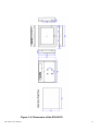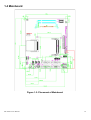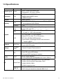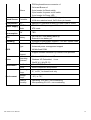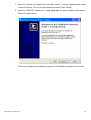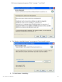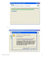
1
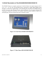
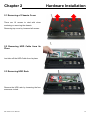
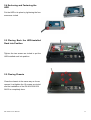
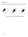
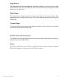
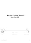
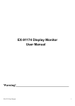
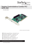
EX-96083 / 96103 / 96123 / 96153
(Human Machine Interface)
User Manual
Release Date
Oct. 2007
®2005 TOPSCCC Technology, Inc.
Taiwan
Revision
All Rights Reserved.
V0.1
Published in
TOPSCCC Technology, Inc.
E-mail: [email protected] URL: WWW.TOPSCCC.COM
EX-96XX3 User Manual
1
Warning!________________________________
This equipment generates, uses and can radiate radio frequency energy and if not installed and
used in accordance with the instructions manual, it may cause interference to radio communications. It has been tested and found to comply with the limits for a Class A computing device
pursuant to FCC Rules, which are designed to provide reasonable protection against such
interference when operated in a commercial environment. Operation of this equipment in a
residential area is likely to cause interference in which case the user at his own expense will be
required to take whatever measures may be required to correct the interference.
Electric Shock Hazard – Do not operate the workstation with its back cover removed. There are
dangerous high voltages inside.
Disclaimer
This information in this document is subject to change without notice. In no event shall
TOPSCCC Technology Inc. be liable for damages of any kind, whether incidental or
consequential, arising from either the use or misuse of information in this document or in any
related materials.
EX-96XX3 User Manual
2
Table of Contents______________________
Warning!…………………………………………………………………………….……..….2
Disclaimer………………………………………………………………….…………………2
Chapter 1
1.1
1.2
1.3
1.4
1.5
1.6
Getting Started
Features…....………………….……………………………………..…......5
Specifications………………………………………….………………...….5
Dimensions…………………………………...………………………….…8
Placement of Mainboard……………………………………………..….12
Specifications of Mainboard…………….……………………………….13
Brief Description …………………………..………………….……….…15
Chapter 2
Hardware Installation
2.1 Removing of Chassis Cover….…...…………………………….………16
2.2 Removing HDD Cable from Its Place……...……………………………16
2.3 Removing HDD Rack…..………………...…………..…………………..16
2.4 Enclosing and Fastening the HDD…………………….………………..17
2.5 Placing Back the HDD-installed Rack into Position……….………..…17
2.6 Closing Chassis………...………………………………………………...17
2.7 Panel Mounting………………………….………………………………..18
Chapter 3
Award BIOS Setup
3.1 System Test and Initialization….…...………………………….………19
3.2 Award BISO Setup…………..……………...……………………………20
Chapter 4
Software Utilities
4.1 Introduction..……………………………………………………...............22
4.2 Geode GX3 AES Crypto Driver…..…...………….……...………………..23
4.3 Geode GX3 Audio Driver (WDM)………………………………………….27
4.4 Advanced Micro Device Win XP Graphics Drives…………………………...33
4.5 VIA VT6421 RAID Controller…………...……………………………........38
EX-96XX3 User Manual
3
4.6 Watchdog Timer Configuration………………………………………......43
Chapter 5
_
Touch Screen Installation
5.1 Introduction to Controller Board..…………………..………..……………44
5.2 Windows 2000/XP Driver Installation for Controller Board…..…..…….44
5.3 Configuring PenMount Windows 2000/XP Driver…………….….……..49
5.4 Uninstall PenMount Windows 2000/XP Driver……………….…….….. 54
5.5 Software Functions………………………………..…………..……….….. 55
Figures
Figure
Figure
Figure
Figure
Figure
Figure
Figure
Figure
EX-96XX3 User Manual
1.1: Dimension of EX-96083……………………………………….8
1.2: Dimension of EX-96103……………………………………….9
1.3: Dimension of EX-96123……………………………………….10
1.4: Dimension of EX-96153…..…………………..………….….11
1.5: Placement of Mainboard ……….……..………………………12
1.6: Front View…………………………..….………………………….15
1.7: Rear View…………………………..….………………………….15
2.1: Panelmounting ………………………………………..………….18
4
Chapter 1_____________________________
1.1 Features
z
z
z
z
z
z
8” TFT LCD with resolution of 800x600 for the EX-96083
10.4” TFT LCD with resolution of 800x600 for the EX-96103
12.1” TFT LCD with resolution of 800x600 for the EX-96123
15” TFT LCD with resolution of 1024x768 for the EX-96153
Fanless AMD LX-800 CPU with clock rate of 500MHz
One 200-pin SO-DIMM socket, up to 1GB
resistive touch screen
NEMA 4/IP65 compliant front panel
Input voltage range of 11-28V/DC
1.2 Specifications
System
CPU:
Fanless AMD LX-800 CPU with clock rate of 500MHz
System Memory:
One 200-pin SO-DIMM socket, up to 1GB DDR SDRAM
Storage:
Space for 2.5-inch HDD and 1 compact flash card slot
Power Supply:
Input voltage range of 11-28V/DC
Touch Screen:
Touch screen with 4-wire
I/O Connectors:
COM1: RS-232, DB-9 pin#9 RI/5V/12V selectable
COM2: RS-232/422/485 selectable, DB-9
COM3: RS-232, DB-9
COM4 occupied for touch screen controller
External USB 2.0 connector x2
2x5 2.0mm pin header for internal USB 2.0 x2
PS/2 keyboard/mouse connector x1
On board Buzzer x1
2-pin header for Reset switch
2-pin header for power on/off switch
2-pin header for Power LED
EX-96XX3 User Manual
5
Ethernet port: RJ-45 supporting 10/100Mbps Base-T
Audio: AC'97 Codec, Line-in, Line-out, Mic
1 x CF slot
TOPSCCC Mini PCI Socket
2x SATA port
EMC:
FCC, CE A-level certified
Display
Resolution and color:
8” TFT LCD with resolution of 800x600 for the EX-96083 and maximum color of 262K
10.4” TFT LCD with resolution of 800x600 for the EX-96103 and maximum color of 262K
12.1” TFT LCD with resolution of 800x600 for the EX-96123 and maximum color of 262K
15” TFT LCD with resolution of 1024x768 for the EX-96153 and maximum color of 262K
Luminance:
EX-96083 : 400 cd/m2
EX-96103 : 250 cd/m²
EX-96123 : 300 cd/m²
EX-96153 : 400 cd/m²
Viewing angle:
EX-96083 : Top 55 / Bottom 65 / Left 65 / Right 65
EX-96103 : Top 55 / Bottom 55 / Left 65 / Right 65
EX-96123 : Top 40 / Bottom 55 / Left 60 / Right 60
EX-96153 : Top 50 / Bottom 50 / Left 60 / Right 60
Backlight:
Lifetime of 50,000 hours
Mechanical
Construction:
Aluminum alloy front panel and metal housing
Color:
Black front panel
Dimensions:
EX-96XX3 User Manual
6
EX-96083 : 231(W) x 75.5(D) x 176mm(H)
EX-96103 : 317(W) x 62(D) x 243mm(H)
EX-96123 : 317(W) x 62(D) x 243mm(H)
EX-96153 : 409(W) x 69(D) x 309mm(H)
Weight:
Environment
Operating temperature:
0~50°C
Storage temperature:
0~60°C
Relative humidity:
10~90% @ 40°C non-condensing
Vibration:
1G / 5 ~ 500Hz (Random) / Operation
Shock:
15G peak acceleration(11 msec. duration)/operation
EX-96XX3 User Manual
7
1.3 Dimensions
Figure 1.1: Dimension of the EX-96083
EX-96XX3 User Manual
8
Figure 1.2: Dimension of the EX-96103
EX-96XX3 User Manual
9
Figure 1.3: Dimension of the EX-96123
EX-96XX3 User Manual
10
Figure 1.4: Dimension of the EX-96153
EX-96XX3 User Manual
11
1.4 Mainboard
Figure 1.5: Placement of Mainboard
EX-96XX3 User Manual
12
1.5 Specifications
Feature
Items
Board Layout
Detail
Processor
CPU
•AMD Geode LX800 500MHz
•64KBI-cache/64KB D-cache
•128KB L2 cache
•AMD CS5536
Chipset
Memory
Description
•PCB: 6 Layer with double side
•Dimensions: 150.1mm x193mm
Type
Capacity
Graphic
Chip
CRT
Graphic
LCD
•One 200-pin SO-DIMM socket, up to 1GB Non-ECC
Non-registered DDR SDRAM
•1GB
•The Geode LX800 integrated Graphic, supports both
standard VGA and TFT
•CRT supports up to 1600x1200x32 bpp at 85Hz
D_sub 15 CRT VGA connector
•DF-14 for 18bit TTL LCD interface
•40-pin FPC for 18bit TTL LCD interface
•DF-14 for 18/24bit LVDS interface
•5-pin header for backlight inverter with luminance
control by BIOS
•RJ-45 10/100Base-T support Wake On LAN function
•2-pin LAN LED header
Network
LAN Chip
Storage
Compact
Flash
•Internal Compact Flash socket x1
IDE
•44-pin connector x1, support Ultra DMA 33/66/100
•2-pin IDE active LED header
•On board SATA interface x2 (option)
Audio
AC97
•AC-97 audio interface
•3.5mm phone jack with Speaker-out, Line-in, Mic-in
I/O
•COM1: RS-232, DB-9 pin#9 RI/5V/12V selectable
•COM2: RS-232/422/485 selectable, DB-9
Serial Ports
•COM3: RS-232, DB-9
•COM4 for touch screen
USB 2.0
EX-96XX3 User Manual
•External USB 2.0 connector x2
•2x5 2.0mm pin header for internal USB 2.0 x2
13
Others
Touch Screen Controller
•PS/2 keyboard/mouse connector x1
•On board Buzzer x1
•2-pin header for Reset switch
•2-pin header for power on/off switch
•2-pin header for Power LED
•On board Penmount DMC9000 support
4/5/8 wire resistive touch, 2x5 2.0mm pin header
IO Expansion
PCI
•Special PCI Interface for Mini PCI Riser Card or others
Power Supply
AT/ATX
Mode
•DC 10.8 ~ 28V input support AT and simulate
ATX mode
Power
Consumption
PW
•TBD
RTC
Battery
•On Chip RTC with battery back up
External Li-ion battery x1
•Software programmable support 1~255 sec. system reset
Watchdog
•AWARD system BIOS
Type
BIOS
Driver
Certification
Environment
Advanced power management support
4M bits flash ROM
ACPI
Support
•Support software shutdown by internal 5Vsb provided
Operating
Systems
•Windows 2000, Windows XP
Windows XP Embedded, Linux
WinCE 4.2, WinCE 5.0
Certification •Meet CE/FCC Class A
RoHS
•RoHS component and process
Operating
Temp.
•0℃ to 60℃ for board level only
Storage
Temp.
•-10℃ to 75℃
Relative
Humidity
•Operating 10%~90%, non-condensing
Non-operating 5%~95~, non-condensing
EX-96XX3 User Manual
14
1.6 Brief Description of the EX-96083/96103/96123/96153
The EX-96XX3 Series is a compact, panel-mount industrial fanless touch panel computer with 8”/
10.4” / 12.1” / 15” TFT LCD. The EX-96XX3 Series is powered by a AMD LX800 500MHz based
processor. It comes with a compact flash, 2.5-inch hard disk drive, One 200-pin SO-DIMM socket, up
to 1GB, 3 com ports, audio, Ethernet, DC input, and two USB ports. The unit supports Windows 2000
Professional, Windows XP, and CE.Net. The compact, fanless touch panel computer is ideal for use
as Web Browser, Terminal and HMI at all levels of automation control.
Figure 1.6: Front View of EX-96103/96123/96153
Figure 1.7: Rear View of EX-96103/96123/96153
EX-96XX3 User Manual
15
Chapter 2
Hardware Installation
2.1 Removing of Chassis Cover
There are 10 screws to deal with when
enclosing or removing the chassis.
Removing top cover by loosened all screws.
2.2 Removing HDD Cable from Its
Place
Just take off the HDD Cable from its place
2.3 Removing HDD Rack
Remove the HDD rack by loosening the four
screws as circled.
EX-96XX3 User Manual
16
2.4 Enclosing and Fastening the
HDD
Put the HDD in its place by tightening the four
screws as circled
2.5 Placing Back the HDD-installed
Rack into Position
Tighten the two screws as circled to put the
H6D-installed rack into position.
2.5 Closing Chassis
Close the chassis in the same way as it was
opened. Just tighten the 10 screws as circled
and the installation of the EX-96103/96123/
96153 is completely done.
EX-96XX3 User Manual
17
2.7 Panel Mounting
The EX-96xx3 HMI Controller is designed to be panel-mounted as shown in Figure 2.1. Just carefully
place the unit through the hole and tighten the given 9 screws from the rear to secure the mounting.
Figure 2.1: Panelmounting of EX-96083/96103/96123/96153
EX-96XX3 User Manual
18
Chapter 3
Award BIOS Setup
3.1 System Test and Initialization
These routines test and initialize board hardware. If the routines encounter an error during the tests,
you will either hear a few short beeps or see an error message on the screen. There are two kinds of
errors: fatal and non-fatal. The system can usually continue the boot up sequence with non-fatal errors.
Non-fatal error messages usually appear on the screen along with the following instructions:
Press <F1> to RESUME
Write down the message and press the F1 key to continue the boot up sequence.
System configuration verification
These routines check the current system configuration against the values stored in the CMOS memory.
If they do not match, the program outputs an error message. You will then need to run the BIOS setup
program to set the configuration information in memory.
There are three situations in which you will need to change the CMOS settings:
1. You are starting your system for the first time
2. You have changed the hardware attached to your system
3. The CMOS memory has lost power and the configuration information has been erased.
EX-96XX3 User Manual
19
3.2 Award BIOS Setup
Awards BIOS ROM has a built-in Setup program that allows users to modify the basic system
configuration. This type of information is stored in battery-backed CMOS RAM so that it retains the
Setup information when the power is turned off.
Entering Setup
Power on the computer and press <Del> immediately. This will allow you to enter Setup.
Standard CMOS Features
Use this menu for basic system configuration. (Date, time, IDE, etc.)
Advanced BIOS Features
Use this menu to set the advanced features available on your system.
Advanced Chipset Features
Use this menu to change the values in the chipset registers, optimize your system performance and
set up output display.
Integrated Peripherals
EX-96XX3 User Manual
20
Use this menu to specify your settings for integrated peripherals. (Primary slave, secondary slave,
keyboard, mouse etc.)
Power Management Setup
Use this menu to specify your settings for power management. (HDD power down, power on by ring,
KB wake up, etc.)
PnP/PCI Configurations
This entry appears if your system supports PnP/PCI.
PC Health Status
This menu allows you to set the shutdown temperature for your system.
Load Fail-Safe Defaults
Use this menu to load the BIOS default values for the minimal/stable performance for your system to
operate.
Load Optimized Defaults
Use this menu to load the BIOS default values that are factory settings for optimal performance
system operations. While AWARD has designated the custom BIOS to maximize performance, the
factory has the right to change these defaults to meet their needs.
Set Supervisor Password/User Password
Use this menu to set Supervisor and User Password.
Save and Exit Setup
Save CMOS value changes to CMOS and exit setup.
Exit Without Saving
Abandon all CMOS value changes and exit setup.
EX-96XX3 User Manual
21
Chapter 4
Software Utilities
4.1 Introduction
A support CD-ROM for EX-96xx3 is available and along with product. There are related utilities and
drivers of EX-96xx3 for Windows XP. Please insert the support CD-ROM into your CD-ROM bay and
install the Geode GX3 AES Crypto Driver, Audio Driver, Graphics Driver, RAID Controller and Touch
Panel Driver.
Please kindly refer to the following chart:
Filename
(Assume that CD ROM drive is D:)
D:\driver\Castle_XP_WDM_AES_v2.00.03
Purpose
Geode GX3 AES Crypto Driver
(Entertainment Encryption/ Decryption Controller)
D:\driver\Castle_XP_WDM_Audio_V2.01.04 Geode GX3 Audio Driver (WDM)
(Multimedia Audio Controller)
D:\driver\Castle_XP_XPe-Graphics_v2.01.05 Advanced Micro Device Win XP Graphics Drives
(Video Controller-VGA Compatible)
D:\driver\vt6421
VIA VT6421 RAID Controller
C:\Program Files\PenMount Universal Driver Touch Panel Driver
EX-96XX3 User Manual
22
4.2. Geode GX3 AES Crypto Driver
Please follow the steps to install Geode GX3 AES Crypto Driver.
Step 1: Insert the CD-ROM and go to “Device Manager”. Click “Entertainment Encryption/
Decryption Controller”
EX-96XX3 User Manual
23
Step 2: Please go to “Driver” tab to update the driver
Step 3: Then follow the update Wizard processors.
EX-96XX3 User Manual
24
EX-96XX3 User Manual
25
EX-96XX3 User Manual
26
Step 4: After you successfully update the driver, you can see the successfully installed from the
device manager.
4.3 Geode GX3 Audio Driver
Please follow the steps to install Geode GX3 Audio Driver.
Step 1: Please go to “Device Manager”. Click “Multimedia Audio Controller”
EX-96XX3 User Manual
27
Step 2: Please go to “Driver” tab to update the driver
EX-96XX3 User Manual
28
Step 3: Then follow the update Wizard processors.
EX-96XX3 User Manual
29
EX-96XX3 User Manual
30
EX-96XX3 User Manual
31
Step 4: After you successfully update the driver, you can see the successfully installed from the
device manager.
EX-96XX3 User Manual
32
4.4 Advance Micro Devices Win XP Graphics driver
Please follow the steps to install Graphics Driver.
Step 1: Please go to “Device Manager”. Click “Video Controller (VGA compatible)”
EX-96XX3 User Manual
33
Step 2: Please go to “Driver” tab to update the driver
Step 3: Then follow the update Wizard processors.
EX-96XX3 User Manual
34
EX-96XX3 User Manual
35
EX-96XX3 User Manual
36
Step 4: After you successfully update the driver, you can see the successfully installed from the
device manager.
EX-96XX3 User Manual
37
4.5 VIA VT6421 RAID Controller
Please follow the steps to install RAID Driver.
Step 1: Please go to “Device Manager”. Click “RAID Controller”
EX-96XX3 User Manual
38
Step 2: Please go to “Driver” tab to update the driver
Step 3: Then follow the update Wizard processors.
EX-96XX3 User Manual
39
EX-96XX3 User Manual
40
EX-96XX3 User Manual
41
Step 4: After you successfully update the driver, you can see the successfully installed from the
device manager and you hardware settings have changed, you must restart your computer for these
changes to take effect. Click “Yes”.
EX-96XX3 User Manual
42
4.6 Watchdog Timer Configuration
This board has watchdog timer function for monitoring whether the system is still working or
not after a period of time. The user can select watchdog timer to system reset or NMI (Non
Maskable interrupt) depending on the jumper set in “Reset/NMI/Clear Watchdog Selection”.
This is defined at I/O port 443H. When you want to enable the watchdog timer, please write I/O
port 443H, and then the system will either reset itself or perform the NMI function. Likewise,
when you want to disable the function, write I/O port 441H, the system will run the command to
stop the Watchdog function.
In the Prox-7360 watchdog function, you must write your program in such that it writes I/O port
address 443 to enable watchdog and writes I/O port address 441 to disable watchdog. The
timer's intervals have a tolerance of 25%, so you should program an instruction that will
refresh the timer about every second.
The following program shows you how to program the watch timer in your program.
Watchdog enable program:
MOV AX, 000FH (choose the values you need; start from 0)
MOV DX, 443H
OUT DX, AX
Watchdog disable program:
MOV AX, 000FH (this value can be ignored)
MOV DX, 441H
OUT DX, AX
The Watchdog Timer control table is as follows:
Level
Value
Time/sec
Level
Value
Time/sec
1
F
0
9
7
64
2
E
8
10
6
72
3
D
16
11
5
80
4
C
24
12
4
88
5
B
32
13
3
96
6
A
40
14
2
104
7
9
48
15
1
112
8
8
56
16
0
120
EX-96XX3 User Manual
43
Chapter 5
Touch Screen Installation
5.1 Introduction to Touch Screen Controller Board
The control board is configured for use with the RS-232 interface. It connects to the touch screen,
power supply and computer system’s RS-232 port, and supports 4-, 5- and 8-wire touch screens. The
control board has some advanced functions, such as PnP and non-PnP mode adjustable baud rate,
thus making easy for customers to select different touch screens without changing the control board.
The size of the board is 25 by 60mm, and it has two connectors and one dipswitch on-board.
Figure 5.1: Bird’s Eye View of Control Board
5.2 Windows 2000/XP Driver Installation for Control Board
Before installing the Windows 2000/XP driver software, you must have the Windows
2000/XP system installed and running on your computer. You must also have the 9036
PenMount Serial Interface controller board installed. Contents of the PenMount
Windows 2000/XP driver folder are listed below:
DMC9000.inf
DMC9000.sys
DMC9000.cat
SETUP.EXE
If you have an older version of the PenMount Windows 2000/XP driver installed in your
system, please remove it first. Follow the steps below to install the PenMount Windows
2000/XP driver.
EX-96XX3 User Manual
44
1. When the system first detects the controller board, a screen appears that shows
“Unknown Device”. Do not use this hardware wizard. Press Cancel.
2. Insert the TOPSCCC product cd install setup.exe. the screen below would appear.
Click touch panel driver
The screen displays the installation wizard for the PenMount software. Click “Next”.
EX-96XX3 User Manual
45
3. A License Agreement appears. Click “I accept…” and “Next”
4. The “Ready to Install the Program” screen appears. Choose Install Location
5. The next screen is installing...
EX-96XX3 User Manual
46
6. The next screen is “Hardware Installation”. Select “Continue Anyway”
EX-96XX3 User Manual
47
7. PenMount Universal Driver 1.0 has been installed on your computer. Click “Finish” to
close this wizard.
EX-96XX3 User Manual
48
5.3 Configuring the PenMount Windows 2000/XP Driver
Upon rebooting, the computer automatically finds the new 9036 controller board. The
touch screen is connected but not calibrated. Follow the procedures below to carry out
calibration.
1. After installation, click the PenMount Monitor icon “PM” in the menu bar.
2. When the PenMount Control Panel appears, click “Calibrate”.
PenMount Monitor Menu Icon
The PenMount monitor icon (PM) appears in the menu bar of Windows 2000/XP system
when you turn on the PenMount Monitor in the PenMount Utilities.
5.3.1 The PenMount Monitor has the following functions:
5.3.2 Control Panel
Devic : Click “configure” for Calibrate
EX-96XX3 User Manual
49
Multiple Monitors
You con select “Multiple Monitor Support”
Tools
The functions of the tools are Draw, Advanced Calibration, Right Button Icon,
and Screen Rotation Monitor.
EX-96XX3 User Manual
50
About
This panel displays information about the PenMount controller and this
driver version.
5.3.3
Beep
Turns beep on or off.
PenMount Control Panel
The functions of the PenMount Control Panel are Calibrate,Setting and About, which
are explained in the following sections.
Calibrate
EX-96XX3 User Manual
51
This function offers the calibration your touch screen. “Standard Calibration” adjusts
most touch screens.
Standard Calibration
EX-96XX3 User Manual
Click this button and arrows appear pointing to
red squares. Use your finger or stylus to touch
the red squares in sequence. After the fifth red
point calibration is complete. To skip, press
‘ESC’.
52
Setting
Click setting to start.
About
This panel displays information about the PenMount controller and this driver version.
EX-96XX3 User Manual
53
5.3.4 Right Button
When you select this function, a mouse icon
appears in the right-bottom of the screen. Click
this icon to switch between Right and Left
Button functions.
5.3.5 Exit
Exits the PenMount Monitor function.
5.4 Uninstall the PenMount Windows 2000/XP Driver
1. Exit the PenMount monitor (PM) in the menu bar.
2. Go to Settings, then Control Panel, and then click Add/Remove program. Select
PenMount DMC9000 and click the Add/Remove button.
EX-96XX3 User Manual
54
3. Select PenMount DMC9000 and DMC9100. Click the Remove button.
4. Select “Yes” and “Close” to remove the PenMount Windows 2000/XP driver, and
reboot the system.
5.5 Software Functions
Standard Calibration
The Standard Calibration function lets you match the touch screen to your display so that
the point you touch is accurately tracked on screen. Standard calibration only requires
four points for calibration and one point for confirmation. Under normal circumstances,
Standard Calibration is all you need to perform an accurate calibration.
Advanced Calibration
The Advanced Calibration function improves the accuracy of calibration by using more
involved engineering calculations. Use this function only if you have tried the Standard
Calibration and there is still a discrepancy in the way the touch screen maps to the
display. You can choose 4, 9, 16 or 25 points to calibrate, though we suggest that you
first try 9 points, if it is still not tracking well then try 16 or 25 points. The more points you
use for calibration, the greater the accuracy. Errors in calibration may occur due to
viewing angle, or individual skill, and there may be little difference in using 16 or 25
points. Note that a stylus is recommended for the most accurate results.
EX-96XX3 User Manual
55
Stream/Point Mode
Stream and point modes control the touch and drag function of the touch screen. The
point mode only allows “touch” interaction with the screen and does not allow the user to
drag objects. The point mode is useful for maintaining the location of screen icons such
on POS terminals. The stream mode allows a user to touch and drag icons and other
items around on the screen, similar to using a mouse.
Drawing Mode
Drawing mode is a utility that lets the user draw on the screen using a finger or stylus.
This allows the user to test the touch screen and touch controller to see if it is operational
or is mapped correctly. The drawing mode can display either the matrix address of points
touched or just show lines drawn. One of the PenMount driver’s strengths is a special
mathematical algorithm that minimizes the occurrence of noise and smooths the drawing
of lines.
Beep Sound
All of PenMount’s drivers support the beep sound function; however, some PC systems
may only offer a fixed buzzer sound.
Beep Sound Adjustable
Software drivers for Windows systems let the user adjust the frequency and length of the
beep sound. The drivers let the user adjust the desired touch screen sound, as well as
turn the sound off.
Wake Up Function
The Wake Up function lets the user touch the screen and wake the system up from
‘suspend’ mode.
Point Calibration Data
The Plot Calibration Data function displays the touch screen linearity map, which is
available if the PenMount driver provides an Advance Calibration function when touch
screens age their touch linearity declines. This non-linearity is apparent when the
touched point on the touch screen is not the same as the point on the display. The plot
calibration data function shows the linearity status of the touch screen. This is only a
support function for the user. The exact linearity of a touch screen requires a linearity
test machine.
EX-96XX3 User Manual
56
Right Button
The Right Button function simulates the right button function of a mouse. Click the right
button and the user can only touch the screen once and the driver changes the touch
definition to the left button.
Hide Cursor
The Hide Cursor function keeps the cursor arrow and other cursor symbols from
appearing when using the touch screen. The cursor appears when the user turns this
function off.
Cursor Offset
The Cursor Offset function lets the user adjust the position of the touch point to a desired
location away from the real touch point.
Double-Click Area and Speed
The Double-Click Area and Speed function lets the user adjust the double-click area and
speed to their personal preference.
About
This option shows the exact version of the drivers and controller firmware. Updated
drivers are available for download on the PenMount website.
EX-96XX3 User Manual
57